University of Huddersfield Repository
Liu, Dezheng, Xu, Qiang, Lu, Zhongyu and Barrans, Simon
The development of finite element software for creep deformation and damage analysis of
weldment
Original Citation
Liu, Dezheng, Xu, Qiang, Lu, Zhongyu and Barrans, Simon (2013) The development of finite
element software for creep deformation and damage analysis of weldment. In: 6th International
‘HIDA’ Conference: Life/Defect Assessment & Failures in High Temperature Plant, 2nd4th
December 2013, Nagasaki, Japan.
This version is available at http://eprints.hud.ac.uk/id/eprint/21772/
The University Repository is a digital collection of the research output of the
University, available on Open Access. Copyright and Moral Rights for the items
on this site are retained by the individual author and/or other copyright owners.
Users may access full items free of charge; copies of full text items generally
can be reproduced, displayed or performed and given to third parties in any
format or medium for personal research or study, educational or notforprofit
purposes without prior permission or charge, provided:
•
The authors, title and full bibliographic details is credited in any copy;
•
A hyperlink and/or URL is included for the original metadata page; and
•
The content is not changed in any way.
For more information, including our policy and submission procedure, please
contact the Repository Team at: [email protected].
The development of finite element software for creep deformation and damage
analysis of weldment
Dezheng Liu1, Qiang Xu2, Zhongyu Lu3, Simon Barrans4
School of Computing and Engineering, University of Huddersfield, Huddersfield HD1 3DH, UK
1[email protected]; 2[email protected]; 3[email protected]; 4[email protected];
Corresponding author: Qiang Xu, [email protected]
Abstract: This paper presents the development of finite element software for creep deformation and damage analysis of weldment. The development and benchmark test of the software under plane stress, plane strain, axisymmetric, and 3 dimensional cases were reported in previous work [1]. This paper primarily consists of two parts: 1) the structure of the new FE software and the existing FE library applied in obtaining such computational tool via an approach for stress and field variable updating; 2) the development and validation of stress update; and 3) the development of validation of multi-material zones version. This paper contributes to the computational creep damage mechanics in general and particular to the design and the development of finite element software for creep damage analysis of multi-material zone.
Key words: Finite Element Software, Multi-material Zones, Continuum Damage Mechanics, Creep Damage, Validation
1. Introduction
The finite element method has already shown to provide numerical scientists with adequate means for simulating creep damage mechanics. The standard finite element subroutines and Continuum Damage Mechanics (CDM) can support the analysis of creep damage behaviors. Creep damage mechanics has been developed and applied to analyze creep deformation and the simulation for the creep damage evolution and rupture of high temperature components [2-4].
The computational capability can only be obtained by either the development and the application of special material subroutine in junction with standard commercial software (such as ABAQUS or ANSYS) or the development and application of dedicated in-house software [5].
The need of such computational capability and the justification for developing in-house software was identified and was reported in the early stage of this research [1, 5-6]. Essentially, the creep damage problem is of time dependent, non-linear material behaviour, and multi-material zones. Becker, et al [7] and Hayhurst, et al [8] has reported the development and the use of their in-house software for creep damage analysis. Furthermore, Hayhurst has reported the use of Runge-Kutta integration method [9], later on; Ling et al [10] presented a detailed discussion and the use of Runge-Kutta type integration algorithm. On the other hand, it was noted that Xu [11] revealed the deficiency of Kachanov-Rabatnov-Hayhurst (KRH) formulation and proposed a new formulation for the multi-axial generalization in the development of creep damage constitutive equations. The new creep damage constitutive equations for low Mo steel and for high Cr-Mo steel are under development in this research group [12-13].
This paper presents the latest progress in the development of finite element software for creep deformation and damage analysis of weldment. More specifically, it reports firstly the structure of the new FE software and the existing FE library applied in obtaining such computational tool via an approach for stress and field variable updating; and secondly, the development and validation of stress update and multi-material zone version .
2. Overview of the system
Fig.1. The flow diagram of the structure for developing FE software [15]
Fig. 1 shows the procedures for the development of such computational finite element software and the procedures can be summarized in:
1. Input the definition of a specific FE model including nodes, element, material property, boundary condition, type of creep damage constitutive equations, as well as the computational control parameters
2. Calculate the initial elastic stress and strain
3. Integrate the constitutive equation and update the field variables such as creep strain, damage, stress; the time step is controlled
4. Remove the failed element [16] and update the stiffness matrix 5. Stop execution and output results
Fig.2. Classes for dynamic arrays, input and initialisation
The elastic and elastic-plasticity programming from literature [17] was carefully studied, and the overall structure and the relevant standard subroutines/library [17] were adopted whenever possible for programming efficiency. Dynamic array has good flexibility, convenience and efficiency; therefore, all of the arrays used in programming are dynamic arrays. The boundary conditions are stored in “dat” file and they can be read by main program [17]. The components of weldment are complex, thus the function of creep damage analysis for multi-materials is essentially. In this program, nprops and np_types are two integer variables; they represent the number of material property and number of different property type respectively. etype is a dynamic integer array and it represents element property type vector. prop is a dynamic real array and it represents element properties. No matter single material model or multi-materials model, the program can check the material property type automatically and all the material parameters are provided by “input-dat” file.
g_coord is a dynamic real array and it represents nodal coordinates for all elements. g_num is a dynamic integer array and it represents global element node numbers matrix. Both g_coord and g_num are provided by “input-dat” file through the FEM pre-processing. Consequently, the generality of the program can be increased since the modular design of program.
2.2 The finite element algorithm
The finite element algorithm [18] for creep damage problems is briefly introduced as follows by governing equations and corresponding stress updating equations.
The governing equations are assuming that the total strain ε can be partitioned into the elastic and creep strains, thus the total strain increment can be expressed as:
Δε = Δεe + Δεc (1)
where Δε, Δεe and Δεc is total strain increment, elastic strain increment, and creep strain increment, respectively [12].
The stress increment is related to the elastic and creep strain increments by:
where D is the stress-strain matrix and it contains the elastic constants.
The stress increments are related to the incremental displacement vector Δu by:
Δσ = D(BΔu – Δεc) (3)
where B is strain-displacement matrix. The equilibrium equation to be satisfied any time can be expressed by:
∫vBTΔσdv = ΔR (4)
where ΔR is the vector of the equivalent nodal mechanical load and v is the element volume. Combining equations (3) and (4):
∫vBTD(BΔu – Δεc)dv = ΔR (5)
2.3 Creep damage constitutive equation
The creep damage constitutive equations are the mathematical description of the relation between creep deformation, creep damage and external applied stress. There are different types of creep damage constitutive equations. One example is Kachanov-Rabatnov-Hayhurst (KRH) constitutive equations and it is included here due to its popularity.
Uni-axial form [18]:
{
𝜺̇ = 𝑨 𝒔𝒊𝒏𝒉((𝟏−𝝋)(𝟏−𝝎)𝑩𝝈(𝟏−𝑯) ) (6.1)
𝑯̇ =𝒉𝝈(𝟏 −𝑯𝑯∗) 𝜺̇ (6.2)
𝝋̇ =𝑲𝑪
𝟑 (𝟏 − 𝝋)𝟒 (6.3)
𝝎̇ = 𝑪𝜺̅̇∗ (6.4)
(6)
where A, B C, h, H* and Kc are material parameters. H (0 < H < H*) indicates strain hardening during primary creep, φ (0< φ < 1) describes the evolution of spacing of the carbide precipitates [18].
Multi-axial form [18]:
{
𝜺𝒊𝒋̇ =𝟑𝑺𝟐𝒊𝒋𝑨𝒔𝒊𝒏𝒉((𝟏−𝝋)(𝟏−𝝎)𝑩𝝈𝒆(𝟏−𝑯) ) (7.1)
𝑯̇ = 𝒉
𝝈𝒆(𝟏 −
𝑯
𝑯∗) 𝜺̇ (7.2)
𝝋̇ =𝑲𝑪
𝟑 (𝟏 − 𝝋)𝟒 (7.3)
𝝎̇ = 𝑪𝜺𝒆̇ 〈𝝈𝟏 𝝈𝒆〉
𝝂 (7.4)
(7)
where 𝜎𝑒 is the Von Mises stress, 𝜎1 is the maximum principal stress and ν is the stress state index
defining the multi-axial stress rupture criterion [18].
The intergranular cavitation damage varies from zero, for the material in the virgin state, to 1/3, when all of the grain boundaries normal to the applied stress have completely cavitated, at which time the material is considered to have failed [19]. Thus, the critical value of creep damage is set to 0.3333333 in the current program. Once the creep damage reaches the critical value, the program will stop execution and the results will be output automatically.
Other type of creep damage constitutive equations will be incorporated in the FE software in future.
2.4 The integration scheme
{
𝛆𝐧+𝟏= 𝛆𝐧+ 𝛆̇ ∗ ∆𝐭 (8.1) 𝑯𝐧+𝟏= 𝑯𝒏+ 𝐇̇ ∗ ∆𝐭 (8.2)
𝝋𝒏+𝟏= 𝝋𝒏+ 𝛗̇ ∗ ∆𝐭 (8.3) 𝛚𝐧+𝟏 = 𝛚𝐧+ 𝛚̇ ∗ ∆𝐭 (8.4)
𝒕𝒏+𝟏= 𝒕𝒏+ ∆𝐭 (8.5)
(8)
It is noted that D02BHF (NAG) [21] integrates a system of first-order ordinary differential equations using Runge-Kutta-Merson method. This subroutine can be adopted in the FEA software of creep damage analysis development, and more sophisticated Runge-Kutta type integration scheme will be adopted in future.
2.5 The stress update algorithm
Creep deformation can be regarded as a time-related plastic deformation and the process of the creep damage is absolutely transient. Thus, the accuracy of finite element results would be influenced as a result of the residual stress during the increment of the time. The Absolute Method [14] has been given for the solution of the structural creep damage problems and the finite element algorithm for updating the stress has been developed.
The principle of virtual work applied to the boundary value problem is given:
Pload = [Kv] × TOTD – Pc (9)
where Pload is applied force vector, and [Kv] is the global stiffness matrix, which is assembled by the
element stiffness matrices [Km]; TOTD is the global vector of the nodal displacements and Pc is the global
creep force vector.
[Km] = ∫∫[B]T[D][B]dxdy (10)
The [B] and [D] represent the strain-displacement and stress-strain matrices respectively.
TOTD = [Kv]–1 × (Pload + Pc) (11)
The initial Pc is zero and the Choleski Method [13] is used for the inverse of the global stiffness matrix
[Kv]. By giving the Pload, the elastic strain εek and the elastic stress σekfor each element can be obtained:
εek = [B] × ELD (12)
σek = [D] × εek (13)
The element node displacement ELD can be found from the global displacement vector and the creep strain rate εckrate for each element can be obtained by substituting the element elastic stress into the creep
damage constitutive equations. The creep strain can be calculated as:
εck(t + △t) = εcK(t) + εcKrate × △t (14)
The node creep force vectors for each element are given by:
Pck = [B]T[D] × εcK (15)
The node creep force vector Pck can be assembled into the global creep force vector Pc and the Pc is
used to up-date Eq. (9). Thus, the elastic strain can be updated:
εtotk= [B] × ELD = εek + εck (16)
εek= [B] × ELD – εck (17)
where the εtotk and εck represents the total strain and creep strain for each element respectively; and the
3. The preliminary validation of the software 3.1 The validation of stress update program
[image:7.595.238.359.164.319.2]The validation of this software for stress update was performed and it was conducted via a plane strain case in Fig.3 [1]. The width of this model is set to 5 meters. The Young's modulus E and Poisson's ratio υ are set to 1000 MPa and 0.3 respectively. An equivalent linear distributed load 10 KN/m was applied on the top line of this model.
Fig. 3. Plain strain tension model [1]
The theoretical stress in Y direction can be shown as:
𝝈𝒚 =𝑷
𝑨=
50
5.0= 10 KN/𝑚2
The theoretical stress in Z direction can be shown as:
𝝈𝒛= 𝐄 ∗ 𝝐𝒛= 𝐄 ∗ 𝛖 ∗ 𝝐𝒚= 𝐄 ∗ 𝛖 ∗𝝈𝒚
𝐄 = 3KN/𝑚2
The stress and displacement obtained from FE software with the stress updating invoked due to creep deformation are shown in Fig. 4 and Fig. 5.
[image:7.595.132.253.456.610.2]
Fig. 4. Stress distribution in Y direction at rupture time Fig. 5. Stress distribution in Z direction at rupture time
[image:7.595.67.521.714.754.2]Using the theoretical stress value into the multi-axial version of creep constitutive equations, the theoretical rupture time and damage can be obtained without stress update by a testified subroutine [17] and the results are shown in Table 1
Table. 1. The damage obtained from FE software at failure
Rupture time Creep damage
Fig. 6. The damage distribution on 180230h
The Fig. 4 and Fig. 5 show the results obtained from the FE software do agree with the expected theoretical values.
Table 1 and Fig. 6 have revealed that rupture time and damage obtained from FE software have a good agreement with the theoretical values obtained from the subroutine [22].
3.2 The validation of the multi-materials version
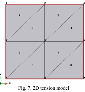
[image:8.595.229.363.69.239.2]The validation of new software for multi-materials version was performed and it was conducted via a two-dimensional tension model in Fig. 7. In this program, the number of material property nprops is set to 1 and 2 separately. The number of different property type np_types is set 2 (Young's modulus E and Poisson's ratio υ). The length of a side is set to 1 meter. The Young's modulus E and Poisson's ratio υ are set to 1,000 MPa and 0.3 respectively. A uniformly distributed linear load 40 KN/m was applied on the top line of this uni-axial tension model. Table 2 shows the material property of each element when nprops is set to 1 and when nprops is set to 2 respectively.
Fig. 7. 2D tension model
Table. 2. The material property of each element when nprops = 1 and nprops =2 respectively
nprops Materials group 1 (E and υ) Materials group 2 (E and υ)
Nprops=1 Element No.1, 2, 3, 4, 5, 6, 7 and
8 No element
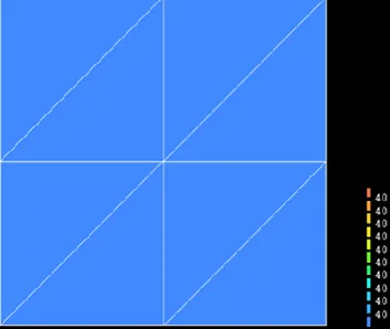
[image:8.595.204.386.465.661.2]Fig. 8. The stress distribution in Y direction at rupture time when the nprops = 1
Fig. 9. The stress distribution in Y direction at rupture time when the nprops = 2
When nprops = 2, that means there are two kinds of material properties. In program, assuming two kinds of material properties in model; but the values of material properties in “input-dat” file are all same from nprops = 1 to nprops = 2. Thus, the stresses distribution in y direction between nprops = 1 and nprops
= 2 should be same. Fig. 8 and Fig. 9 have a good agreement with this deduction.
4. Conclusion
This paper is to present the finite element method based on CDM to design FE software for creep damage mechanics. More specifically, it presents briefly the structure of an object-oriented finite element program for creep damage analysis; secondly, it reports the development of such software including the development of finite element algorithms based on CDM for creep damage analysis, and the use of some standard subroutines in programming; thirdly, the development and the validation of the finite element software include stress update and multi-materials were reported.
Working in this area is on-going and future development work includes: 1) development and incorporation the new constitutive equation subroutines; 2) intelligent and practical control of the time steps; 3) removal of failed element and updating stiffness matrix; 4) further validation, and 5) real case study. It will be reported in due course.
Reference
[1] Liu, D., Xu, Q. and Lu, Z. Research in the development of finite element software for creep damage analysis, Journal of communication and computer, 2013, ISSN 1548-7709. (accepted and to be published)
[2] Lemaitre, J. and Chaboche, J. L. Mechanics of Solid Materials, Cambridge University Press, 1st ed. Cambridge, 1994.
[image:9.595.210.387.244.393.2][4] Murakami, S., Continuum Damage Mechanics: A Continuum Mechanics Approach to the Analysis of Damage and Fracture, Springer, 2012.02.23, ISBN 9400726651.
[5] Liu, D., Xu, Q., Lu, Z. and Xu, D. The review of computational FE software for creep damage mechanics, Advanced Materials Research, vol. 510, 2012, pp. 495-499.
[6] Liu, D., Xu, Q., Lu, Z., Xu, D. and Tan, F. The validation of computational software system for creep damage analysis, Advanced Materials Research, vol.744, 2013, pp. 449-454.
[7] Becker, A.A., Hyde, T.H., Sun, W. and Andersson, P. Benchmarks for finite element analysis of creep continuum damage mechanics, Computational Materials Science, Vol. 25, 2002, pp. 34-41.
[8] Hayhurst, D. R. and Krzeczkowski, A. J. Numerical solution of creep problems, Comput. Methods App. Mech. Eng., vol. 20, pp.151-171, 19.
[9] Hayhurst, D.R., Dimmer, P.R. and Morrison, G.J. Development of continuum damage in the creep rupture of notched bars, Trans R Soc London A 311, 1984, pp. 103-129.
[10] Ling, X., Tu, S.T. and Gong, J. M. Application of Runge-Kutta-Merson algorithm for creep damage analysis, International Journal of Pressure Vessels and Piping, vol. 77, 2000, pp. 243-248
[11] Xu, Q. Creep damage constitutive equations for multi-axial states of stress for 0.5Cr0.5Mo0.25V ferritic steel at 590◦C, Theoretical and Applied Fracture Mechanics, vol. 36, 2001, pp. 99-107.
[12] Xu, Q.H., Xu, Q., Lu, Z. and Barrans, S. A Review of Creep Deformation and Rupture Mechanisms of Cr-Mo Alloy for the Development of Creep Damage Constitutive Equations under Lower Stress, Journal of communication and computer, 2013, ISSN 1548-7709. (accepted and to be published)
[13] Xu, Q.H., Xu, Q., Pan, Y.X. and Short, M. Current state of developing creep damage constitutive equation for 0.5Cr0.5Mo0.25V ferritic steel, Advanced Materials Research, vol. 510, 2012, pp. 812-816.
[14] Robert, I. M. An object-oriented approch to calculation control in finite element programs, Computer and Structure, vol.77, 2000, pp.461-474.
[15] Liu, D., Xu, Q., Lu, Z. and Xu, D., Research in the development of computational FE software for creep damage mechanics, in: Proceedings of the 18th International Conference on Automation & Computing, Loughborough, Sep. 7-8, 2012.
[16] Wong, M.T. Three-Dimensional Finite Element Analysis of Creep Continuum Damage Growth and Failure in Weldments, PHD thesis, University of Manchester, UK, 1999.
[17] Smith, I.M. and Griffiths, D.V. Programming the Finite Element Method, 4th ed., John Wiley & Sons Ltd., Sussex, 2004.
[18] Leckie, F.A. and Hayhurst, D.R. Constitutive equations for creep rupture, Acta Metallurgical, vol. 25 1977, pp. 1059-1070.
[19] Perrin, I.J. and Hayhurst, D.R. Creep constitutive equations for a 0.5Cr–0.5Mo–0.25V ferritic steel in the temperature range 600–675°C, J. Strain Anal. Eng 31, 1996, pp. 299-314.
[20] Tan, F., Xu, Q., Lu, Z. and Xu, D. The preliminary development of computational software system for creep damage analysis in weldment, in: Proceedings of the 18th International Conference on Automation & Computing, Loughborough, Sep. 7-8, 2012.
![Fig. 3. Plain strain tension model [1]](https://thumb-us.123doks.com/thumbv2/123dok_us/343927.1035412/7.595.238.359.164.319/fig-plain-strain-tension-model.webp)