Journal of Chemical and Pharmaceutical Research, 2013, 5(9):498-506
Research Article
CODEN(USA) : JCPRC5
ISSN : 0975-7384
Development of self-adaptively loading for planetary roller
traction-drive transmission
Desheng Chen and Xuewen Du
College of Vocational and Technical Education, Zhejiang University of Technology, Hangzhou, China _____________________________________________________________________________________________
ABSTRACT
Traction drives offer certain advantages over gear drives. In particular, they generally run more quietly than geared units and provide an opportunity for higher speed and higher efficiency by eliminating sliding motion between contacting elements. Generating adequate normal load at the frictional contact is essential for traction drives. The best way to generate the normal force is the slef-adaptively loading to prevent the rollers under a continuous and high-stress load. In this paper, a novel design of planetary traction-drive device was developed. It is a combination of a planetary cylindrical roller configuration and a logarithmic spiral profile connection. In this device, the sun roller is hollow, and connected to the input shaft by a logarithmic spiral profile. So as the input shaft rotates relative to the sun roller according a certain direction, a wedging action takes place between the input shaft and the sun roller. This makes the sun roller generate a certain amount of elastic deformation, so an appreciable amount of contact load is generated between the contacting elements. The greater the input torque is, the stronger the strength of the wedging action, and the greater the contact load, and vice versa. So this device is self-actuating and self-adaptive. This design offers an alternative way to solve the problem of self-adaptively loading of the planetary cylindrical roller traction drive.
Keywords: Traction-drive, planetary roller mechanism, self-adaptively loading, profile connection, logarithmic spiral
_____________________________________________________________________________________________
INTRODUCTION
Traction drive possesses desired performance attributes that pertain to its unique operating principles. These attributes include high mechanical efficiency, little or no backlash, low noise and vibration and high-speed capability. The power density of a traction drive can be very high when operated at elevated speeds. These performance features, in conjunction with its inherent manufacturing simplicity, make traction drives suitable candidates for a host of applications.
Traction drives can be broadly classified into variable-speed ratio drives and fixed-speed ratio drives. Generating adequate normal load at the frictional contact is essential for traction drives. Planetary configuration has been the preferred arrangement for fixed-speed ratio drives because the internal forces are well balanced. A common practice is to use tapered raceways along the axial direction. By moving these raceways axially, a radial displacement and thus normal force are generated. Examples of such designs were disclosed in [1, 2].
on the planetary rollers. This design featured a torque-actuated roller-ramp loading mechanism, offering improved torque capability. It looks as if the problem of spin motion has been solved, but when the shape of the tapered planetary rollers were revised in shape in order to improve the contact stress distribution, the spin motion would reoccur.
Cylindrical annular rollers could eliminate the spin motion. However, the torque-actuated roller ramp mechanism is not applicable to this case. Instead, the normal load was generated by using oversized rollers before. The magnitude of the load was controlled by precisely pre-set internal interference. This imposes severe constraints on manufacturing and assembling. Moreover, when a traction drive of such design is operated at partial torque, contact components are unnecessarily overloaded. This places the rolling components under a continuous, high-stress load and reduces the durability of the traction drive.
So in a word, if tapered rollers were used in the planetary roller mechanism, the spin motion would occur likely; while if cylindrical rollers were used, the spin motion would not happen, but it would be required to solve the problem of self-adaptive loading for the planetary roller mechanism. This problem has been studied by Ai etal [4] who developed an eccentric cylindrical planetary design and by Flugrad and Qamhiyah [5] who used a different principle involving pairs of intermediate rollers to produce the normal force on torque demand. Also, this problem is the subject of this paper, in which a new way to solve this problem will be presented.
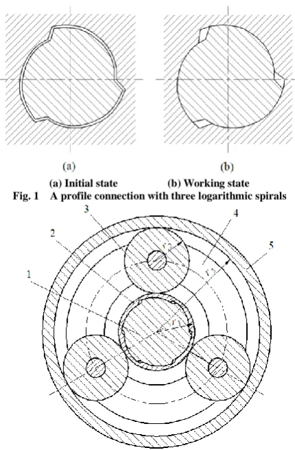
(a) Initial state (b) Working state Fig. 1 A profile connection with three logarithmic spirals
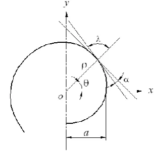
Fig. 2 A planetary cylindrical roller traction-drive device
1. Input shaft. 2. Sun roller. 3. Planetary rollers. 4. Planet carrier. 5. Outer ring.
OPERATING PRINCIPLES
[image:2.595.197.412.288.616.2]configuration is self-actuating. Here, as cylindrical rollers are used in the planetary traction-drive device, such a spin motion as would present in the case where tapered rollers were used will not occur.
GEOMETRIC DESIGN FOR PROFILE CONNECTION
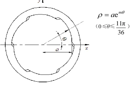
In mathematics, a logarithmic spiral refers to the track of a moving point its moving direction keeps a fixed angle λ with its polar radius, as seen in Figure 3. The polar coordinate equation of logarithmic spirals can be expressed as
aem, wherea
andm
are constants, is referred to as the polar angle, and
is referred to as the polar radius.In a logarithmic spiral,
a
decides the size of the logarithmic spiral, whilem
decides the shape. When a logarithmic spiral is used in a profile connection, the value ofm
decides the magnitude of the wedge angle
, which in turn decides the frictional self-locking status of the curved wedge. Here, the profile connection is used for self-adaptive loading, so it is not permissible for it to be self-locking. That is to say, the following relationship must be satisfied:tan
tan (90g
)1/ tan
m f [image:3.595.227.380.291.441.2]where
f
is the coefficient of friction between the shaft and the hub.Fig. 3 Geometry of logarithmic spiral
If a logarithmic spiral profile connection is used to transmit torque, its cross-section contour only requires being capable of centring, and normally consists of three segments of logarithmic spiral. Here, the logarithmic spiral profile connection is to be used for the planetary cylindrical roller traction drive. The aim of doing so is to obtain the radial elastic deformation of the sun roller and then to obtain the normal force needed for traction drive through the profile connection between the input shaft and the hollow sun roller. Under the condition that the input torque is constant, the greater the amount of radial elastic deformation of the hollow sun roller, the greater the normal forces between the rollers of the traction-drive device, and then the higher the capacity of the transmission. In order to obtain a greater elastic deformation under the condition that the minimum wall thickness of the hollow sun roller satisfies the tensile strength, a thin average wall thickness is desired. If only three segments of logarithmic spiral were employed in the cross-section outline of the profile connection, the length of each segment of logarithmic spiral would be longer, and the average wall thickness of each segment of wall would be thicker, and then the elastic deformation of the hollow sun roller would be smaller. Increasing the number of segments of logarithmic spiral would effectively reduce the average wall thickness. Considering that the wedging stroke is not long, six segments of logarithmic spiral could be selected. Figure 4 shows the cross-section contour of the profile connection. It consists of six segments of logarithmic spiral, and in each segment of logarithmic spiral, the value of
is defined as from0
1
Fig. 4 Interface contour of profile connection
FORCE ANALYSIS
In order for the planetary traction-drive device to work properly, relative sliding is not permissible between the rolling elements. This can be referred to as the frictional self-locking condition for this device, and can be further explained as follow: When a torque is applied to the input shaft, a wedging action takes place between the input shaft and the hollow sun roller. The wedging action makes the hollow sun roller produce a certain amount of radial elastic deformation. This makes the hollow sun roller apply a contact load to the planet rollers and outer ring. This contact load is needed for the planetary traction drive. To prevent sliding between the rolling elements, the frictional forces generated by the contact load should overcome the working torque applied to the planetary traction-drive device.
Contact Stress of Profile Connection
pProvided there is an ideal condition to the fit between the input shaft and the hollow sun roller, and a torque is applied to the input shaft, as shown in Figure 5, then an appreciable amount of contact stress is thus generated at the
six sections of working surface of the profile connection. Taking any pointPfrom theABsection, so in the infinitesimal
d
s
that contains the pointP, the summing of the moments about pointo
will produce the following expression:)
d
cos
d
sin
(
d
T
p
l
s
pf
l
s
(sin
f
cos
)
p
l
d
s
(1)where
pis contact stress between two fitted surfaces,
is polar radius of the pointP
,l
is fit length between twofitted surfaces,
is included angle between
pand
, andf
is coefficient of friction between two fitted surfaces.
Fig. 5 Calculation model of contact stress of profile shaft
From the characteristics of the logarithmic spiral, we have
(0≤θ≤
36 π 11 )
ma
e
[image:4.595.232.448.76.214.2]So, the total moment exerted by the three pieces of working surface of the profile connection is as follows:
(sin
cos
)
e
d
6
d
6
36 2π 11 0 p 36 π 11 0 m
l
a
T
T
m
f
l
a
m)
1
e
)(
cos
(sin
3
18 π 11p
Thus, the contact stress is
)
1
e
)(
cos
(sin
3
18 π 11 p
mf
al
mT
(2)Contact Load between Rollers P
In this design of a planetary roller traction drive, as the contact load for the traction drive is produced through the elastic deformation of the hollow sun roller, so its value can be calculated by analysing the elastic deformation of the hollow sun roller. In order to simplify the theoretical calculation, the hollow sun roller its wall thickness is actually not uniform, can be seen a uniform thickness sleeve, as seen in Figure 6. In this simplified model, the inner wall of the sleeve is subjected to a uniformly distributed load
p
and constrained by the input shaft; the outer wall is constrained by three equally distributed planetary rollers, so it is subjected to three equally distributed contact loads (reactions) P. Obviously, this sleeve is an internal-force statically indeterminate system. According to the principle of deformation superposition, two deformation quantities,u
and
, can be calculated respectively. Here,u
is the radial deformation quantity of the sleeve produced by the internal pressurep
, and
is the contact deformation quantity between the rollers caused by the three contact loads P. Then, according to the deformation compatibility condition of the sleeve at point C, that is
u
, the contact load P could be calculated.Fig. 6 Free-body diagram of sleeve
Calculation of Radial Deformation Quantity
u
: The calculating model of the radial deformation quantity of this thin-walled sleeve is shown in Figure 7. The calculating formula of the radial deformation of a thin-walled sleeve is [7]Et
pr
u
2 1
(3) [image:5.595.229.377.370.527.2]
Fig. 7 Calculation model of radial deformation of sleeve
Calculation of Contact Deformation Quantity
: The calculation model of the contact deformation quantity of this planetary roller traction-drive device is shown in Figure 8. There are two places at which the contact deformation occurs: one is between the sun roller and the planetary rollers; the other is between the planetary rollers and the outer ring. The quantities of contact deformation at the two places are named ianderespectively. In engineering, Palmgren’s formula is usually used to calculate the line-contact elastic deformation [8], so we get0.9 5 i e 2 3.847 10 0.8
P L
(4)where
L
is the contact length of two contacting bodies.Fig. 8 Calculation model of contact deformation of traction-drive device
Deformation compatibility equation: Provided that only the contact elastic deformation is considered while the whole elastic deformation is neglected for the planetary roller and the outer ring, then the deformation compatibility equation can be expressed as
u
e i
write out the analytic solution.
STRENGTH DESIGN
In order to simplify calculations, the following strength conditions are based on an assumption of simple stress.
Compressive Strength Condition
The compressive strength condition for the profile connection pair is
p
≤ [
p] (7)where
pis the compressive stress of the profile connection pair, [
p]is the allowable compressive stress.Tensile Strength Condition
The hollow sun roller is taken as a thin-walled sleeve, and squeezed by the profile shaft, so it is subjected to a circumferential tensile stress. The circumferential tensile stress may make the hollow sun roller produce the plastic deformation and even rupture. Therefore, the tensile strength condition for the hollow sun roller is
p
t
r
θ
1
≤ [
] (8)where
θis the circumferential tensile stress of the hollow sun roller, [
] is the allowable tensile stress.Contact strength Condition
According to the Hertz theory, the contact strength condition for two cylindrical bodies is
2 2 2 1 2 1 2 1 H1
1
π
)
1
1
(
E
E
L
P
≤ [
H] (9)in which,
His maximum contact stresses for two bodies, [
H] is allowable contact stresses for two bodies,1
and
2are radius of curvature for two bodies respectively,
1and
2are Poisson’s ratios for two bodies respectively,E
1andE
2are modulus of elasticity for two bodies respectively.DESIGN EXAMPLE
If the device as shown in Figure 2 is to be used for a speed reducer, and taking the sun roller as the input member, the planet carrier as the output member and the outer ring as the stationary member, then the speed ratio of this device would be
i
1
r
3/
r
1, wherer
1andr
3are the radius of the sun roller and the outer ring. Supposing4
i
is required for a certain application, then a radius of 21mm for the sun roller and 63mm for the outer ring will satisfy the speed requirement. Once the radius of the sun roller is known, the thickness of the sleeve at the thinnest wallt
and the constant of logarithmic spirala
could be determined. The thinnest wallt
can be calculated through the use of Eq. (8), and the constant of the logarithmic spirala
can be calculated through the following formulas:)
(
1
r
t
a
in which,
(
e
e
)
(
e
361
)
π 111
2
m m ma
a
.After the geometric parameters of the planetary roller traction-drive device are determined, solving equations (2), (3), (4), (5) and (6) simultaneously, and noting that
p
p
, the required minimum friction coefficient to ensure self-locking for the planetary roller traction drive can be obtained.52100 steel is
S=1700Mpa. If the safety factor of the profile connection is selected asS 1.25, then the allowablecompressive stress between the input shaft and the hollow sun roller is p s/S =550/1.25=440Mpa, and the
allowable tensile stress of the hollow sun roller is
s/S =1700/1.25=1360Mpa. As stated in [5], theallowable contact stress of the rollers and raceways is [
H] =4000~4500Mpa.Having determined the geometric parameters of the traction-drive device, substituting the input torque
T
into Equation (2),
pis obtained; substitutingp
pinto Equation (3),u
is obtained; substituting
i
e
u
intoEquation (4),
P
is obtained; substitutingP
andT
into Inequality (6), the frictional locking condition, that is, the minimum value of
could be obtained; substitutingp
pinto the left term of Inequality (8),
θis obtained;substituting
P
into the left term of Inequality (9),
His obtained. The calculations have been summarized in Table 1 and Table 2.Table 1 Calculations at
t
2
.
3
mm
T
N·m
a
mm
p [image:8.595.221.391.266.447.2]MPa θ
MPa H
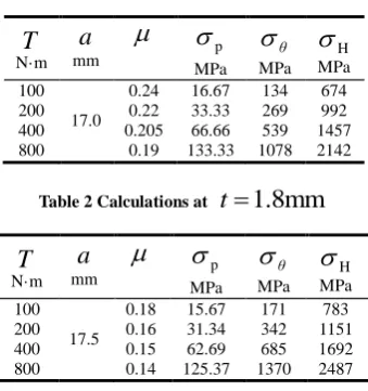
MPa 100 200 400 800 17.0 0.24 0.22 0.205 0.19 16.67 33.33 66.66 133.33 134 269 539 1078 674 992 1457 2142Table 2 Calculations at
t
1.8mm
T
N·m
a
mm
p MPa θ
MPa H
MPa 100 200 400 800 17.5 0.18 0.16 0.15 0.14 15.67 31.34 62.69 125.37 171 342 685 1370 783 1151 1692 2487The results of calculation for
in Table 1 and Table 2 show:(1) Under a certain wall thickness condition, as the input torque increases, the value of the minimum friction coefficient needed to satisfy the self-locking condition for the traction drive will decline slightly. This explains that the self-locking condition for the traction drive is mainly relevant to the geometric parameters and the elastic modulus of the material, and has little relevance to the input torque.
(2) Under a certain input torque condition, as the wall thickness reduces, the value of the minimum friction coefficient needed to satisfy the self-locking condition for the traction drive will decline obviously. This is because, as the wall thickness reduces, the radial elastic deformation of the sun roller increases. Thus, the contact loads between the rollers increases, so the value of the minimum friction coefficient needed declines. But the reduction in the wall thickness is limited by the tensile strength of the hollow sun roller.
Based on the preceding analysis, it is shown that the calculation results are logical. This shows that the foregoing theoretical calculation has certain reliability.
The results of calculation for
p,
θand
H have also been listed in Tables 1 and 2, so as to compare them withdevice proposed by Flugrad and Qamhiyah [5].
This research not only expands the method of self-adaptive loading for cylindrical roller planetary traction drives, but also extends the utilization of logarithmic spiral profile connections.
Future research is planned to experimentally measure the efficiencies for the proposed design. The stress distribution between the rolling elements will be determined by finite element analysis. The stresses will then be used to predict the expected fatigue life of the system, and experimental tests will be conducted to verify the life predication.
Acknowledgment
This research was supported by Zhejiang Provincial Natural Science Foundation of China (ZJNSF No. Y1110418).
REFERENCES
[1] LO Hewko. AIAA J. Hydronaut, 1968, 2, 160−167. [2] R Zhou. U.S. patent, 1997, No. 5, 688,201.
[3] X Ai; T J Rybkoski. U.S. patent, 2000, No. 6, 095,940.
[4] X Ai; M Wilmer; D Lawrentz. ASME J. Tribol., 2005, 127, 857−864. [5] DR Flugrad; AZ Qamhiyah. ASME J. Mech. Des., 2005, 127, 631−636. [6] YY Zheng. Journal of Machine Design, 2003, 20(1), 69−70 (In Chinese).