Parameter Optimization Study and Performance Analysis of 6S-8P
Permanent Magnet Flux Switching Machine with Field Excitation for High
Speed Hybrid Electric Vehicles
Erwan Sulaiman, Takashi Kosaka, Nobuyuki Matsui
Dept. of Electrical & Computer Engineering, Nagoya Institute of Technology,
Gokiso, Showa, Nagoya, Aichi, 466-8555 Japan
Tel.: +81 / (52) – 7355420
Fax: +81 / (52) – 7355420
E-Mail: [email protected]
URL: http://motion.elcom.nitech.ac.jp/
Keywords
«Permanent magnet flux switching machine», «Field-excitation», «Hybrid electric vehicles»
Abstract
Over the past decade, many automotive companies have been commercializing HEVs. Most of them employ interior permanent magnet synchronous machine (IPMSM) using rare-earth magnet as their main traction drives from viewpoints of high torque and power density and high efficiency over most of operating torque-speed ranges. However, since all permanent magnets (PMs) are located on rotor part, a design approach to ensure mechanical strength of the rotor depends on rib thickness and number of bridges between PMs. The increase in the number of bridges improves the mechanical strength, but reduces the maximum torque of the machine due to an increase in leakage flux of PM. To overcome this problem, 6S-8P permanent magnet flux switching machine with additional field excitation coil is presented. The proposed machine has all active parts on the stator body and a rugged rotor structure suitable for high speed operation. Some design parameter refinements are conducted to this machine in order to elevate maximum torque and maximum power densities. As a result, it is shown that the proposed machine after the design refinements becomes a good candidate for target HEV drive applications.
Introduction
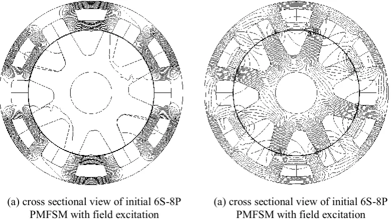
permanent magnet flux switching machine (PMFSM) with additional field excitation coil has been proposed [4, 5]. In this structure, all active parts such as armature coil, permanent magnet and field excitation coil are located in the stator body, while the rotor consists of only stacked soft iron sheets. Fig. 1(a) shows 6S-8P PMFSM as an example. The working principle of this machine is similar to the original 12S-10P machine discussed in [4] and [5]. In the example shown in Fig. 1(a), the machine is composed of 6 permanent magnets and 6 field excitation coils distributed uniformly in the midst of each armature coil. The term, “flux switching”, is created to describe machines in which the stator tooth flux switches its polarity by following the motion of a salient pole rotor. In this 6S-8P machine, the permanent magnets and field excitation coils produce three north poles interspersed between three south poles. The three phase armature coils are accommodated in the 6-slots for each 1/2 stator body periodically. As the rotor rotates, the fluxes generated by permanent magnet and mmf of excitation coil link with the armature coil alternately. For the rotor rotation through 1/8 of a revolution, the flux linkage of the armature has one periodic cycle and thus, the frequency of back-emf induced in the armature coil becomes eight times of the mechanical rotational frequency. The cross sectional view of flux paths caused by both permanent magnet and mmf of field excitation coil of the initial design are depicted in Fig. 1(b).
With all active parts located on the stator and robust single piece rotor similar to that of the switched reluctance machine (SRM), this machine has the advantages of easy cooling of all active parts and better suitability for high speed application with high mechanical strength compared to conventional IPMSM. In addition, the additional field excitation coil gives extra advantage to the machine as secondary flux sources that can improve torque and power with the assistance of variable flux control capability. The original machine design presented in Ref. [4] has some drawbacks. Authors have conducted design improvements in Ref. [6-8]. This type of machine is classified into hybrid excitation machines which are also becoming more popular over the years [9-10]. This paper presents an investigation into design possibility of 6S-8P PMFSM with additional field excitation coil for traction drives in HEVs. Some design refinements and parameter optimization based on 2D-FEA are conducted to achieve the target performances. In addition, the rotor mechanical strength, the PM demagnetization at high temperature, the torque and power versus speed characteristics, the loss and the efficiency of the final designed machine are also predicted.
Fig. 1: 6S-8P PMFSM with field excitation and the flux path of permanent magnet and mmf of field excitation coil.
Stator yoke
Rotor
Excitation coil
Armature Coil
Shaft Permanent
Magnet
(a) cross sectional view of initial 6S-8P
[image:2.595.97.476.479.729.2]Design restriction and specification of the proposed machine
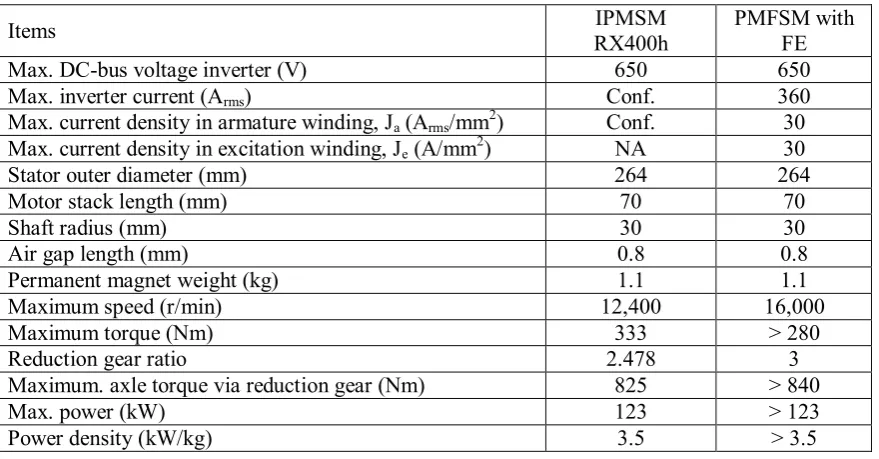
Design restrictions and specifications of the proposed machine for HEV applications are similar with IPMSM for LEXUS RX400h listed in Table I [11]. The electrical restrictions related with the inverter are set to be much severe. The limit of the current density is set to the maximum of 30A/mm2 for both armature and field excitation coil. The outer diameter 264mm, stack length 70mm and shaft radius 30mm of the target machine are identical with those of IPMSM. The target maximum torque 280Nm is determined from a realization of comparable maximum axle torque with the present IPMSM via reduction gear ratio 3:1. It can be expected that the rotor structure is mechanically robust to rotate at high speed, so that the target maximum operating speed is elevated up to 16,000r/min. The target maximum power is set to be more than 123kW and the motor weight to be designed is less than 35kg, resulting in the maximum power density of 3.5kW/kg similar with the estimated of IPMSM in LEXUS RX400h.
Commercial FEA package, JMAG-Studio ver. 10.0, released by Japan Research Institute (JRI) is used as 2D-FEA solver for this design. The permanent magnet material used in this machine is NMX-S54 whose residual flux density and coercive force at 20C are 1.48T and 1137kA/m, respectively. The electrical steel, 35H210 is used for rotor and stator bodies.
Design Optimization Approach
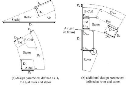
Initially, the drive performances of the proposed machine with rough initial design are calculated. The maximum torque and power obtained are 218.9Nm and 113.3kW which is far from the target requirements. To overcome this problem, design free parameters, D1 to D8 are defined in rotor and
stator sides as illustrated in Fig. 2(a). Basically, the design parameters are divided into three groups such as related to rotor part, field excitation slot shape and armature slot shape. In the figure, the rotor parameters are marked as D1, D2 and D3, the field excitation slot shape parameters are D4, D5 and D6,
and armature slot shape parameters are D7 and D8, respectively.
The first step is carried out by updating rotor parameters, D1, D2 and D3 while keeping D4 to D8
constant. Since the torque increases with the increase in rotor radius, D1 is firstly dealt with as the
dominant variable parameter. Then, the rotor pole depth D2 and rotor pole width D3 are changed while
keeping D1 constant which bring out the higher torque and power capability. Once a combination of
promising parameters D1, D2 and D3 for the highest torque and power is determined, the second step is
[image:3.595.67.507.538.767.2]executed by updating the field excitation slot shape parameters D4, D5 and D6 while keeping other
Table I: Design restrictions and specifications for HEV applications
Items RX400h IPMSM PMFSM with FE
Max. DC-bus voltage inverter (V) 650 650
Max. inverter current (Arms) Conf. 360
Max. current density in armature winding, Ja (Arms/mm2) Conf. 30
Max. current density in excitation winding, Je (A/mm2) NA 30
Stator outer diameter (mm) 264 264
Motor stack length (mm) 70 70
Shaft radius (mm) 30 30
Air gap length (mm) 0.8 0.8
Permanent magnet weight (kg) 1.1 1.1
Maximum speed (r/min) 12,400 16,000
Maximum torque (Nm) 333 > 280
Reduction gear ratio 2.478 3
Maximum. axle torque via reduction gear (Nm) 825 > 840
Max. power (kW) 123 > 123
parameters constant. Then, by using a combination of promising parameters D4 to D6 which bring out
the highest torque and power at the second step, the armature slot shape parameters are updated while keeping other parameters discussed above constant. The necessary armature slot area Sa is determined
by varying armature coil height D7 and armature coil width D8 to accommodate integer number of
turns of armature coil Na.
To obtain further good performances, some other parameters are refined such as the shape of rotor pole, permanent magnet, field excitation slot shape and armature slot shape as shown in Fig. 2(b). These parameters are rotor pole inner and outer widths marked as D3in and D3out, permanent magnet
inner and outer widths marked as D4in and D4out, excitation coil inner and outer pitches marked as D5in
and D5out, and armature coil slot inner and outer widths marked as D7in and D7out, respectively. Firstly,
D3in and D3out are treated as variable parameters for the highest torque and power. Subsequently, D4in
and D4out, D5in and D5out, and D7in and D7out are updated with similar fashion, respectively. At final
stage of the design, a curve shape is designed at rotor inner pole circled in Fig. 2(b) to allow flux to flow smoothly and to increase mechanical strength of the rotor. The design refinement procedure mentioned above is repeated until the target torque and power are fulfilled. All design parameters are adjusted with keeping air gap length 0.8mm and PM weight 1.1kg constant under maximum current density condition. The final designed machine that meets the target performances is shown in Fig 3. The comparisons between initial and final design parameters appear in Table II.
Design results and performances based on Finite Element Analysis
Flux line of permanent magnet and field excitation at no load condition
The flux line at no load condition of the final design machine is illustrated in Fig. 4. Fig. 4(a) shows the flux line due to mmf of permanent magnet only. Fig. 4(b) shows the flux line due to both permanent magnet and mmf of field excitation coil at maximum field excitation current density, Je =
30A/mm2 only. It can be seen that almost 100% flux of permanent magnet flow in the stator iron
around the field excitation coil, resulting in almost no back-emf at open circuit condition.
[image:4.595.75.492.455.745.2]Fig. 2: Design parameters of 6S-8P PMFSM with field excitation.
(b) additional design parameters defined at rotor and stator (a) design parameters defined as D1
to D8 at rotor and stator
Stator
D7out
D2
Air gap (0.8mm)
D6
Rotor D3in
D3out
D4out
D4in
E-Coil
PM
D5out
D5in
D8
D7in
D1
Shaft Rotor D3
D2
Air
E-Coil
Stator
A-coil D7
D8
D5
D6
D4
Rotor mechanical strength
[image:5.595.205.389.89.299.2]The mechanical stress prediction of rotor structure at the maximum speed 16,000r/min is done by centrifugal force analysis based on 2D-FEA. Fig. 5 illustrates the principal stress distributions of the rotor core for the finally designed machine. The highest stress can be found at a point highlighted in circle. It shows that the maximum principal stress at 16,000r/min reaches 77.57MPa which is much smaller than 300MPa being allowable as the maximum principal stress in conventional
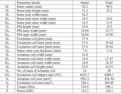
Table II: Initial and final design parameters
Parameter details Initial Final
D1 Rotor radius (mm) 92.2 90.2
D2 Rotor pole height (mm) 31.2 32.2
D3 Rotor pole width (mm) 16.5 -
D3i Rotor pole inner width (mm) 16.5 14.0
D3o Rotor pole outer width (mm) 16.5 11.0
D4 PM height (mm) 16.0 12.5
D4i PM inner width (mm) 10.84 12.77
D4o PM outer width (mm) 10.84 14.98
D5 Excitation coil pitch (mm) 37.4 -
D5i Excitation coil inner pitch (mm) 37.4 35.64
D5o Excitation coil outer pitch (mm) 37.4 38.42
D6 Stator outer core thickness (mm) 7.4 11.0
D7 Armature coil width (mm) 16.0 -
D7i Armature coil inner width (mm) 16.0 17.47
D7o Armature coil outer width (mm) 16.0 18.35
D8 Armature coil height (mm) 22.0 24.33
Na No. of turns of armature coil 16 20
ATe Excitation coil ampere turn (AT) 6232.7 6496.1
Sa Armature coil area (mm2) 350.11 436.34
Se Excitation coil area (mm2) 346.3 360.89
T Torque (Nm) 218.9 290.1
P Power (kW) 112.2 124.1
[image:5.595.67.466.454.762.2]Fig. 3: Final design of 6S-8P PMFSM with additional field excitation Stator yoke
Rotor
Excitation coil
Armature Coil
Shaft Permanent
electromagnetic steel. This is a great advantage of the designed machine that makes it applicable for high-speed application compare to IPMSM.
Magnet demagnetization at high temperature
The demagnetization ratio of permanent magnet (NMX-S54) used in this machine is defined as a volume of permanent magnet demagnetized per total volume of permanent magnet. The knee point on demagnetization curve is referred to identify whether an element of permanent magnet is demagnetized or not. The calculated result shows that even though the PM employed in this machine is with very poor coercivity, its demagnetization is 2.8% under high temperature use as high as 140°C.
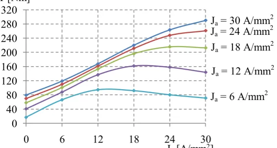
Torque and power factor versus field excitation current density, J
echaracteristics
The torque and power factor versus field excitation current density, Je characteristics are plotted in
Figs. 6 and 7 respectively, where both armature current density, Ja and field excitation current density,
Je are varying from 0 to 30A/mm2. According to the conventional theory on d-q coordinate, the torque
and power factor can be defined as following fashions under the assumptions that d-axis current is controlled to be zero and voltage drop due to the armature resistance is negligible compared to the induced voltage.
m e
qn i
P
T
(1)
[image:6.595.97.487.83.303.2]
Fig. 4: Flux line of permanent magnet and field excitation at no load condition.
Fig. 5: Principal stress distributions of rotor at 16,000r/min (a) cross sectional view of initial 6S-8P
PMFSM with field excitation
(a) cross sectional view of initial 6S-8P PMFSM with field excitation
77.57MPa
80 -
MPa 0 - 40 -
[image:6.595.173.423.338.474.2] e m q qi L PF 1 tan
cos (2)
where Pn is the number of pole-pairs, Øm is the permanent magnet flux linkage and Øe is the flux
linkage produced by mmf of excitation coil.
From the equation it is obvious that increasing the armature current density will increase the torque but will reduce the power factor. Therefore, to equilibrate this situation, the increase in the excitation current density, that is, with the increase in Øe, the power factor can be improved and kept constant
even if the armature current density is very high. The plots clearly show that maximum torque is obtained when Ja and Je are set to 30A/mm2 as their maximum.
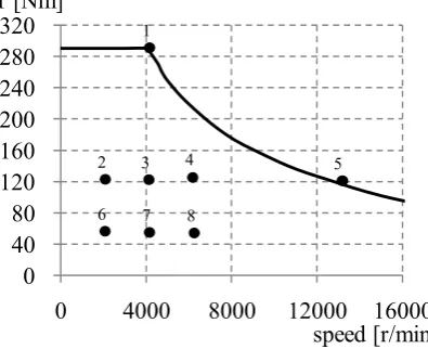
Torque and power versus speed characteristics
The torque and power versus speed curves of the finally designed motor is plotted in Fig. 8. In the figure, the solid black line depicts the maximum torque curve for operating speed of the designed machine and the dotted black line illustrates that of IPMSM for comparison. At base speed 4,084r/min, the torque obtained is 290Nm as the maximum and the corresponding power reaches 124kW with the power factor of 0.43. The maximum power 162.8kW is achieved at maximum speed 16,000r/min. In addition, the average power of 137.7kW is achieved between 6,000 - 7,000r/min. Meanwhile, the total weight of the finally designed machine including the coil end of armature and field excitation windings is 27.9kg, which is 20.3% lighter than original weight of IMPSM. Finally, the maximum torque density and maximum power density obtained are 10.4Nm/kg and 5.8kW/kg, respectively, which is much higher than original IPMSM used in HEV.
Fig. 6: Torque versus Je at various Ja
Fig. 7: Power factor versus Je at various Ja
0 40 80 120 160 200 240 280 320
0 6 12 18 24 30
T [Nm]
Je[A/mm2]
0.0 0.1 0.2 0.3 0.4 0.5 0.6 0.7 0.8 0.9 1.0
0 6 12 18 24 30
pf
Je[A/mm2]
Ja = 6 A/mm2
Ja = 12 A/mm2
Ja = 18 A/mm2
Ja = 24 A/mm2
Ja = 30 A/mm2
Ja = 6 A/mm2
Ja = 12 A/mm2
Ja = 18 A/mm2
Ja = 30 A/mm2
[image:7.595.148.431.405.556.2]Motor loss and efficiency
The motor loss and efficiency are calculated by finite element analysis considering copper losses in armature coil and field excitation coil, and iron losses in all laminated cores. Fig. 9 demonstrates specific operating points at maximum torque, maximum power, and frequent operating point under light load noted as No. 1 to No. 8. Meanwhile, the detailed loss analysis and motor efficiency of the designed machine are summarized in Fig. 10. In the figure, Piis the iron loss, Pc is the copper loss, and Po is the total output power. At high torque operating points No.1, the motor efficiency is 97.4%
although it has the maximum copper loss. At high speed operating point No. 5, the efficiency is 92.4%, degraded due to increase in iron loss. Furthermore, at frequent operating points from No. 2 to No. 4 and No. 6 to No. 8 under operating conditions with relatively low load, the proposed machine achieves relatively high efficiency approximately more than 92%. As a result, it is concluded that the proposed machine can work for specific operating points with high efficiency as much as 92% to 97%. The overall performances of the proposed machine based on finite element analysis are summarized in Table III.
Conclusion
In this paper, a new structure of 6S-8P permanent magnet flux switching machine with additional field excitation for HEV application has been presented. The design refinement procedure to bring out the maximum performance of the proposed machine has been clearly demonstrated. The finally designed machine has satisfied the target requirements. In conclusion, the proposed machine has been able to ensure enough mechanical strength to operate at the required high speed and achieve much torque and power density compared to existing IPMSM for LEXUS RX400h.
[image:8.595.74.284.377.548.2]
Fig. 10: Loss and efficiency of the designed motor over operating points shown in Fig. 9. 0
20 40 60 80 100 120 140 160 180
0 50 100 150 200 250 300 350
0 4000 8000 12000 16000
P [kW] T [Nm]
speed [r/min]
0 40 80 120 160 200 240 280 320
0 4000 8000 12000 16000
T [Nm]
speed [r/min]
84% 88% 92% 96% 100%
1 2 3 4 5 6 7 8
Mo
to
r
Ef
fi
ci
en
cy
Po Pi Pc Fig. 8: Torque and power versus speed
characteristics Fig. 9: Specific operating points for the target HEV drives 1
2 3 4 5
[image:8.595.303.501.385.546.2] [image:8.595.166.435.393.743.2]References
[1] K. C. Kim, C. S. Jin, and J. Lee: “Magnetic shield design between interior permanent magnet synchronous motor and sensor for hybrid electric vehicle”, IEEE Transaction on Magnetics, Vol. 45, No.6 pp. 2835– 2838, June 2009.
[2] K. T. Chau, C. C. Chan, and C. Liu: “Overview of permanent-magnet brushless drives for electric and hybrid electric vehicles”, IEEE Transaction on Industrial Electronics, Vol. 55, No.6 pp.2246–2257, June 2008.
[3] R. Mizutani: “The present state and issues of the motor employed in Toyota HEVs”, Proc. The 29th
Symposium on Motor Technology in Techno-Frontier, Session No.E-3-2, pp.E3-2-1-E3-2-20, April 2009. [4] E. Hoang, M. Lecrivain, and M. Gabsi: “A new structure of a switching flux synchronous polyphased
machine with hybrid excitation”, Proc. of European Conference on Power Electronics and Applications, No.14, Aalborg, Sept. 2007.
[5] E. Hoang et.al: “Experimental comparison of lamination material case switching flux synchronous machine with hybrid excitation”, Proc. of European Conference on Power Electronics and Applications, No.53, Barcelona, Sept. 2009.
[6] E. Sulaiman, Y. Tsujimori, T. Kosaka, and N. Matsui: “Performance analysis of permanent magnet flux switching machine with hybrid excitation”, Proc. International Conference on Electrical Energy and Industrial Electronics System, Malaysia, Dec. 2009.
[7] E. Sulaiman, Y. Tsujimori, T. Kosaka, and N. Matsui: “Design of 12-slot 10-pole permanent magnet flux switching machine with hybrid excitation for hybrid electric vehicles”, Proc. The 5th IET International
Conference on Power Electronics, Machine and Drives, Brighton, April 2010.
[8] E. Sulaiman, T. Kosaka, and N. Matsui: “Design and performance of 6-Slot 5-Pole permanent magnet flux switching machine with hybrid excitation for hybrid electric vehicle applications”, Proc. The 2010 International Power Electronics Conference, Sapporo, June 2010.
[9] J. A. Tapia, F. Leonardi and Thomas A. Lipo: “Consequent-pole permanent magnet machine with extended field-weakening capability”, IEEE Transactions on Industry Applications, Vol. 30, No.6, pp.1704-1709, Dec. 2003.
[10] I. Ozawa, T. Kosaka and N. Matsui: “Less rare-earth magnet-high power density hybrid excitation motor designed for hybrid electric vehicle drives”, Proc. of European Conference on Power Electronics and Applications, No.772, Barcelona, Sept. 2009.
[image:9.595.76.417.97.274.2][11] M. Kamiya: “Development of traction drive motors for the Toyota hybrid systems”, IEEJ Transactions on Industry Applications, Vol.126, No.4, pp.473-479, April 2006.
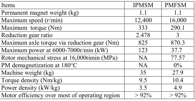
Table III. Performance of finally designed PMFSM with additional field excitation
Items IPMSM PMFSM
Permanent magnet weight (kg) 1.1 1.1
Maximum speed (r/min) 12,400 16,000
Maximum torque (Nm) 333 290.1
Reduction gear ratio 2.478 3
Maximum axle torque via reduction gear (Nm) 825 870.3 Maximum power at 6000-7000r/min (kW) 123 37.7 Rotor mechanical stress at 16,000rimin (MPa) NA 77.57
PM demagnetization at 180°C NA 0%
Machine weight (kg) 35 27.9
Torque density (Nm/kg) 9.5 10.4
Power density (kW/kg) 3.5 4.9