www.ijsrp.org
Area Configuration and Link Failure Effect in IP
Networks using OSPF Protocol
P. R. Gundalwar*, Dr. V. N. Chavan**
*Dept. of MCA, VMV Commerce, JMT Arts & JJT Science College, Nagpur (MS), India **Dept. of CS & IT, S. K. Porwal College, Kamptee, Nagpur (MS), India
Abstract-Open Shortest Path First (OSPF) protocol is widely deployed in IP networks to manage intra-domain routing. An OSPF is a link-state protocol, in which routers establish relationships developing neighbors, enabling each to build a consistent, global view of the routing topology. This paper is based on overview of OSPF comprising different types of routes, routers, networks, areas, and protocols/processes used in OSPF. We used OPNET IT Guru Academic Edition 9.1 network simulator for six different network scenarios to calculate the shortest path from source to destination router. The simulation developed with different parameters and is configured based on OSPF area and link failure using traffic sent in bits/seconds as performance metric. Finally, the research experiment results showed that balance area OSPF is performed better in finding the shortest path in traffic sent after a link fails.
Index Terms- OSPF routes, ABR, ASBR, BR, Packet formats, OPNET
I. INTRODUCTION
outers routes the packets from source to destinations using a road map. Routing can be performed by two ways: static and dynamic. The paths in routing can be defined manually and routes can be installed within the routers in static routing, but this manual work can be replaced by implementing routing algorithms. Dynamic routing analyzes the network traffic to determine the shortest path from source to destination using various metrics. For network routing there are two types of protocols are needed: routed protocols and routing protocols. Routed protocols are used as a means of communication between the underlying devices used in network. Internet Protocol (IP) is the most widely used protocol under the routed protocol category whereas the other examples are AppleTalk, DECnet. Routing protocol is used to determine routes among devices used in network from source to destinations such as Routing Information Protocol (RIP), Enhanced Interior Gateway Routing Protocol (EIGRP), Open Shortest Path First (OSPF) protocol, Intermediate-System to Intermediate-System (ISIS) and Border Gateway Protocol (BGP). The relationship between the routed and routing protocols is routed protocol relies on routing protocol for transport of packets to determine the optimal path over the Internet. Routing protocol maintains routing tables to determine optimal routes by comparing different metrics such as hop count, cost of transmitting link, bandwidth, Maximum Transfer Unit (MTU), and packet delay [2],[7],[8],[9],[10].
II. OSPF ROUTES
Depending upon the router interface and associated AS, there are three types of OSPF routes used in OSPF areas: intra-area routes, inter-area routes and external routes [8],[10]. This is shown in Figure 1. The first two types of routes are concerned directly with the locations of router used in OSPF areas. Intra-area routes form with the interfaces of routers within the same OSPF area whereas inter-area routes form with the interfaces of routers located at different OSPF areas. These both types of routes are internal to OSPF area generated by itself. As the name suggested, external routes are external in the sense that they connects with routers those running other protocol such as RIP, BGP in remote AS to OSPF area. External routes are classified as E1 route and E2 route. The default external route is E2 route. E1 route calculates the route from source by adding the internal and external cost to reach the destination, but E2 routes only considers external cost.
Fig-1: OSPF Route Types
III. OSPF ROUTERS
There are four types of routers used in OSPF as: Internal Routers (IR), Backbone Router (BR), Area Border Router (ARB) and Autonomous System Border Router (ASBR) [7],[8,[10]. This is shown in Figure 2.
IR: Routers those belong to the same OSPF area used for maintaining single current database useful for finding shortest path for other connected areas.
www.ijsrp.org Backbone Router: Routers whose interfaces are connected to
the backbone area.
ABR: Router whose interface connects multiple area with backbone area. The responsibility of ABR is to summarize routing information of each connected area and present to the backbone area for further distribution.
[image:2.612.378.512.62.241.2]ASBR: Routers those redistribute the routing information between OSPF area and non-OSPF running areas.
Fig-2: OSPF Router Types
IV. OSPF NETWORK TYPES
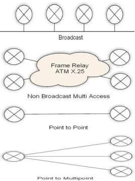
OSPF networks can implement in four different types as Broadcast, Non Broadcast Multi Access (NBMA), Point-to-Point and Point-to-Multipoint [1],[4],[9],[10],[11]. This is shown in Figure 3.
Broadcast: Ethernet or Fiber Distributed Data Interface (FDDI) connects two or more OSPF routers to access multiple end points results in saving bandwidths, faster neighbor discovery and higher scalability. OSPF Hello packets are used to develop neighbor relations. An adjacency can develop with help of electing designated router (DR) and backup designated router (BDR). Neighbor can identify each other by adjacency.
NBMA: Frame relay, ATM or X.25 network use to form NBMA networks. NBMA emulates the function of a broadcast network. OSPF routers need to configure with the IP address of each of its neighbor for establishing relationship. OPPF Hello packets transmitted to each adjacent neighbor forms adjacency. Point-to-Point: This is the simplest type of network that OSPF can implement. Leased lines or High-level Data Link Control (HDLC) connects two or more routers allowing only single-neighbor relationship. There is no need of DR and BDR in point-to-point networks.
Point-to-Multipoint: Routers can be manually configured, if they connected to a non-broadcast network. In real sense, it is a point-to-point network implemented in multiple manners with Private Virtual Circuits (PVCs). This network can occupy a
common subnet without electing DR and BDR.
Fig-3: OSPF Network Types
V. OSPF AREAS
[image:2.612.39.285.184.314.2]OSPF area is identified by a 32-bit number. OSPF uses two broad categories of areas as backbone area and regular area. The backbone area is numbered as 0.0.0.0. The backbone area is the base for other OSPF areas. This area interconnects other areas for fast and efficient transmission of IP packets to find shortest path. Regular area provides user and allows different resources connection. Regular area is configured into different structure as stub area, totally stub area, and Not So-Stuby Area (NSSA). Stub area provides a single exit to outside network forming a dead end. The routers in stub area can reach to outside network using a default route injected by ABR. Totally stub area only allows intra-area routes and default routes within the area. These default routes are used to send traffic outside the area. NSSA allows importing external routes into stub area. ASBR converts stub area into NSSA by connecting an external network running other routing protocol [3],[5],[9]. This is shown in Figure 4.
Fig-4: OSPF Area Types
VI. OSPF PACKETS/PROCESS
[image:2.612.317.564.508.605.2]www.ijsrp.org distributing link state database (LSDB) updates using flooding
[9],[10],[11],[12]. The OSPF packet header is shown in Figure 5.
Fig-5: OSPF Packet Header
The OSPF packet header contains eight fields: Version Identifies the OSPF version being used. Type specifies the type of one of the five different types of OSPF packet. The OSPF packet is used for different routine functionality of OSPF. Hello packet (Type 1) is used for discovering and maintaining neighbor routers. Database description (Type 2) summarizes the database contents. Link state request (Type 3) are used to download topological database from neighbor routers. Type 2 and Type 3 are required to form the adjacency. Link State update (Type 4) is used to update LSDB whenever network changes by LSAs. Link state acknowledgment (Type 5) simply floods the acknowledgements to database for updates using Type 4. Type 4 and Type 5 provides reliable update mechanism. Packet Length specifies the length in bytes including header. Router ID is unique 32-bit number assigned to the router. Single OSPF area can be identified by assigning Area ID. Security can be assigned with checksum field for checking any damage to the packet during transmission. Authentication type and Authentication is used to measure the exchange of OSP packets in authenticated manner. Data field is responsible for carrying upper layer information which is encapsulated.
OSPF packet processes are Hello, flooding and exchange of OSPF packets in OSPF networks.
Hello packets are used to discover the neighbors and exchange the initial parameters in strict order to establish bidirectional communication. In order to exchange LSDB, OSPF routers discover Hello packets before validating time. The different fields used in Hello packet is shown in Figure 6.
Fig-6: Hello Protocol Packet Format
Network mask is associated with the network interface. HelloeInterval field is used to set a time in seconds from the OSPF router to communicate with the neighbors. Precedence setting in number is required to elect Designated Router (DR) in the subnet. This is stored in the Rtr Pri field. RouterDeadInterval
is used to note the state of OSPF router within which it should respond to the Hello request. IP address of the network’s DR and Backup designated Router (BDR) using Designated Router and Backup Designated Router fields respectively. An OSPF router maintains list router IDs of each router that has sent a valid Hello packet using Neighbor field.
When any change or update occurs at interfaces of OSPF routers, link state updates are flooded to every OSPF router’s LSDB. Flooding is used for LSDB synchronization. The packet layout used in flooding process carries with number of advertisements and LSAs. This is shown in Figure 7.
Fig-7: Flooding Process/Protocol
The exchange process is based on bidirectional communication used for synchronizing the LSDB. After synchronization, any changes in the router’s links use the flooding protocol to update all the OSPF routers. The requirement for exchange process is, one of the two routers is master and other is slave. The important field of exchange protocol is shown in Figure 8. The DD sequence number is used to sequence the collection of Database Description (DD) packets. The various types of LSAs are Router, Network, summary (IP Networks), summary (ASBR). The time in seconds for LSA is recorded in LS age field since the LSA was originated. Link state checksum is used for storing complete contents of LSA.
Fig-8: Exchange Process/Protocol Packet Format
VII. SIMULATION SETUP
Implementation is done in OPNET IT Guru Academic Edition 9.1. The simulation scenario setup is given in Table 1.
www.ijsrp.org
Parameters Values
Routing Protocol OSPF
Network type Campus
Scale 10 Km x 10 Km
IP Address Family IPv4
Router Ethernet4-Slip8-Gtwy
Send Style Broadcast
SPF calculation style Periodic
Delay time Hold time
5 sec 10sec
Reference Bandwidth 1000 Mbps Simulation Time 10 minutes
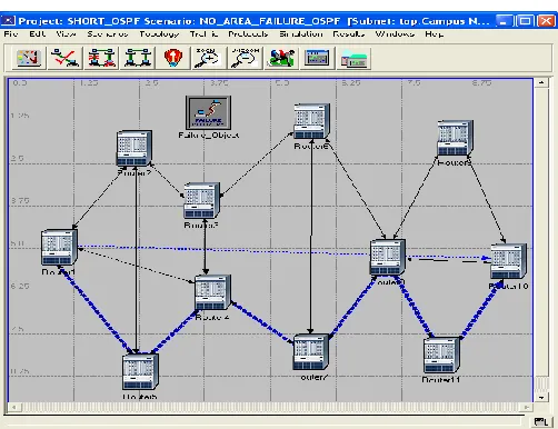
[image:4.612.313.565.63.260.2] [image:4.612.40.290.74.234.2]There are six network scenarios, which are configured as: The scenario N0_AREA_OSPF is configured using the parameters given in Table 4 and the cost as the interface metric information. The traffic demand is set between Router1 and Router10 for traffic sent in bits/seconds. This is shown in Figure 9. In AREA_OSPF scenario, we duplicated the prior scenario by breaking OSPF area into three areas as Area1, Area2 and default Area0 called as backbone of OSPF. This is shown in Figure 10 with different colors. Now, we deploy packet based load balancing between the same pair of routers using BALANCED_AREA_OSPF scenario. We establish link failures between the pair of routers Router1-Router4 and Router8-Router10 by introducing a failure object with delay 0f 100 seconds in all the prior three scenarios duplicated as NO_AREA_FAILURE_OSPF, AREA_FAILURE_OSPF and BALANCED_AREA_FAILURE_OSPF shown in Figure 12, Figure 13 and Figure 14 respectively.
[image:4.612.312.566.288.488.2]Fig-9: Scenario N0_AREA_OSPF
Fig-10: Scenario AREA_OSPF
Fig-11: Scenario BALANCED_AREA_OSPF
[image:4.612.37.289.450.643.2] [image:4.612.315.566.518.711.2]www.ijsrp.org Fig-13: Scenario AREA_FAILURE_OSPF
Fig-14: Scenario BALANCED_AREA_FAILURE_OSPF
VIII. SIMULATION RESULTS AND ANALYSIS
We analyzed the obtained result based on shortest path selection and traffic sent (bits/seconds) for six different scenarios [7].
The shortest path from Router1 to Router10 is calculated for all six scenarios with different path selection. In case of the first three scenarios without introducing link failures, there is no change in path selection. There is no scope in balance area OSPF without failure scenario for alternate shortest path due to existence of link pairs between Router1-Router4 and Router8-Router10. This is shown in Figures 8, 9 and 10. But, change in shortest path selection effect is observed in the last three scenarios where we introduced two link failure pairs for Router1-Router4 and Router8-Router10 for delay of 100 seconds. There are two equivalent shortest paths in balance area failure scenario
from Router1 to Router10. This is shown in Figure 12, Figure 13 and Figure 14.
The traffic sent (bits/seconds) in balance area failure scenario is highest among all the scenarios started with sharp increase upto 17250 bits and after 40 seconds slowed downward to 3750 bits at the simulation end time. This is due to higher traffic created in searching two equivalent shortest paths from Router1 to Router10.
The area scenario is observed with fine increased traffic sent upto 15250 bits over to no area scenario. This means the OSPF protocol increases its performance by administering via areas. But, once we removed area OSPF, then the traffic sent raised initially upto 10000 bits and then downward to 2000 bits. There is significant similarity between the results obtained in area and balanced area scenarios. This is clearly shown in Figure15 where both graphs are overlaid. Finally, it is found that the traffic sent without link failures is higher than link failures scenarios except for balanced area OSPF.
Fig-15: Overlaid Statistics
IX. CONCLUSION
www.ijsrp.org ACKNOWLEDGMENT
We are grateful to OPNET Technologies, Inc. for permitted us to download licensed network simulator OPNET IT Guru Academic Edition 9.1.
REFERENCES
[1] Sam Halabi, OSPF DESIGN GUIDE, Cisco Systems, April, 1996 [Online Available]
[2] Ittiphon krinpayorm, Suwat Pattaramalai, “Link Recovery Comparison Between OSPF & EIGRP”, 2012 International Conference on Information and Computer Networks (ICICN 2012)
[3] Abhimanyu Mehta, Aparna Bhuktar, Kartik Santaluri, Sagar Karale, “ A Resolution To The Equal-Cost Multipath (ECMP) Failure In The OSPF Not-So-Stubby-Areas (NSSA)”, [OnlineAvailable]
[4] Aman Shaikh, Chris Isett, Albert Greenberg, Matthew Roughan, Joel Gottlieb, “A Case Study of OSPF Behavior in a Large Enterprise Network”, [OnlineAvailable]
[5] Atul Aggarwal, Shelej Khera, “ Combat Resources Shortages by making Stub Areas and Route Summarization in OSPF”, IJSRP, Volume 2, Issue 8, August 2012, ISSN 2250-3153
[6] M. Goyal, M. Soperi, E. Baccelli, G. Choudhury, A. Shaikh, H. Hosseini, and K. Trivedi,”Improving convergence Speed and Scalability in OSPF: A Survey”, IEEE Communications Surveys & Tutorials, March 2011 [7] Moy John T.,“OSPF: Anatomy of an Internet Routing Protocol”,
Addison-Wesley Professional, ISBN 0-201-63472-4
[8] Bruce Hartpence, “Packet Guide to Routing and Switching”, O’REILLY, ISBN: 978-1-449-30655-7
[9] Documentation provided by National Weather Service Training Center, “Internetworking Technology Overview”, CISCO Press, June 1999 [10] T. Thomas,”OSPF Network Design Solutions”, Second Edition. Cisco
Press, 2003, ISBN: 1-58705-032-3
[11] Moy Jon T., “OSPF version 2”, Internet Engineering Task Force, Request For Comments (Standards Track) RFC 2328, April. [Online Available] [12] Moy Jon T., “OSPF version 2”, Internet Engineering Task Force, Request
For Comments RFC 1247, July. [OnlineAvailable] [13] www.opnet.com
AUTHORS
P. R. GUNDALWAR, MCA, M.Phil. (CS), Assistant Professor, Dept. of MCA, VMV Commerce, JMT Arts & JJT Science College, Nagpur (MS),India. [email protected]