MODELS AND CROSS-PLATFORM WEB APPLICATIONS FOR
OBJECT MODEL STORAGE
Oleg Jakovlevich Kravets1, Evgeny Vasil’evich Shvedov1, Vasiliy Sergeevich Kireev2, Yurii Borisovich
Mindlin3 and Munavir Zakievich Zakirov4
1Voronezh State Technical University, Moscow ave., Voronezh, Russian Federation
2National Research Nuclear University MEPhI (Moscow Engineering Physics Institute) Kashirskoe highway, Moscow, Russian Federation
3Moscow State University of Mechanical Engineering, Bolshaya Semenovskaya str., Moscow, Russian Federation 4Institute of Management, Economics and Innovatsy Str. Big Dmitrovka, Moscow, Russian Federation
E-Mail: [email protected]
ABSTRACT
The description of the cross-platform web application providing users with the flexible tool for storage of an object model of arbitrary data domain for the purpose of operational formation of controls loading of multi server systems on the basis of scalable Markov processes is provided. The three-level client-server architecture is the cornerstone of system. In it loading is distributed between the service provider called by the server and the customers of services called by clients. In operation ORM a framework of Eclipse Link which is reference implementation of the Java Persistence API (JPA) specifications which were included in Java EE is used. Traditional approach with creation of classes’ entities for each specific type of objects isn't suitable for creation of a data model which would allow keeping objects of arbitrary data domain as neither object types, nor their parameters are in advance unknown. The meta model which describes each object the set of attributes inherent in specific object type, and values for these attributes is developed for the solution of this task. Such approach to the description of objects allows storing arbitrary object model, using a limited set of classes’ entities. The layer of business logic of application is realized by means of JSF Managed Beans or bins - Java of classes which are under control of a container framework (Java EE application server). JSF components of the presentation layer can get directly access to fields and methods. The layer of representation is realized by means of Java Server Faces (JSF) - a platform for creation of the user interface of the web applications written in the Java language and library the Prime Faces 5.2 JSF component.
Keywords: cross-platform web application, flexible tool, storage of an object model, multi server systems, a framework of eclipse link, meta model, arbitrary object model, JSF managed beans.
1. INTRODUCTION
The description of the cross-platform web application providing users with the flexible tool for storage of an object model of arbitrary data domain for the purpose of operational formation of controls loading of multiserver systems on the basis of scalable Markov processes [4, 6, 10] is provided.
According to an objective the chart of options of use of application is made. In system there are two roles - the administrator and the user. The user has an opportunity to view the objects existing in system, to create new objects, to delete objects, to change parameter values of specific object. The administrator, in addition to opportunities which are available to the user can make different operations with a meta model and accounting entries of users, namely:
to view information on object types and attributes;
to create new object types;
to delete object types;
to create new attributes for each object type;
to delete attributes;
to modify attributes;
to view information on users of system;
to create new users;
to delete users.
2. GENERAL ARCHITECTURE OF APPLICATION
Variety of client-server architecture, namely three-level architecture client-server [1] is the cornerstone of the developed system. In it loading is distributed between the service provider called by the server and the customers of services called by clients.
Advantages of this architecture are:
absence of duplicating of a program code of the server by clients;
lowering of the hardware requirements to clients in view of the fact that computation is made on the server;
absence of need of distribution of updates to clients;
on the server it is much easier to provide demarcation of access rights to information.
It is possible to carry to shortcomings of this approach [2, 5]:
need of the qualified support for system operation support [8];
failure of the server leads to an application non service ability at all users;
high cost of the equipment.
The modern corporate environment requires a possibility of scaling [3, 5], a modularity and high speed of development of complex code therefore in this project the three-level (three-unit) architectural model of application will be used. Such model assumes existence in system of three components.
a) The client (the client's layer) - interface, most often graphic, part of system which is provided to the ultimate user. This level shan't comprise business logic, except the elementary things, like check of the value entered by the user on validity, to store application state or to have direct access to the database.
b) An application server (an average, binding layer) - the main part of business logic is concentrated on it. This layer is projected so that to provide horizontal scaling of productivity in case of increase in number of copies without modification of a program code.
c) The layer of data - realizes data storage [11]. Implementation is made by means of different database management systems.
Use of such architecture allows achieving the best scalability best for configurability (due to isolation of layers of application) and ampler opportunities on data security provision and fail safety.
3. LAYER OF DATA ACCESS
In the application developed using object-oriented programming languages, the task of storage of objects is consolidated to conversion them to a look in which they can be saved in tables of the database and to derive afterwards from there, having saved both parameters of objects, and the relations in between. Such objects are called persistent.
For the solution of the task of storage programmers need to write the software which can work data full in an object-oriented look and save them in the relational form. Need to permanently transform data from one form to another creates difficulties when programming, is a source of a large number of errors [9].
To avoid the difficulties given above, different models [7], libraries of object and relational display (ORM library) which relieve the programmer of need of writing of a code for conversion of objects from one form in another are developed.
In operation ORM a framework of EclipseLink which is reference implementation of the Java Persistence API (JPA) specifications which were included in Java EE, starting with the fifth version is used.
3.1. Storable classes entities of the developed system
Traditional approach with creation of classes entities for each specific type of objects isn't suitable for creation of a data model which would allow to keep objects of arbitrary data domain as neither object types, nor their parameters are in advance unknown. The meta model which describes each object the set of attributes inherent in specific object type, and values for these attributes was developed for the solution of this task. Such approach to the description of objects allows to store arbitrary object model, using a limited set of classes entities.
Root element of this hierarchy is the abstract class "Object of a meta model" – Meta Model Object. It contains the id field of the Big Integer type which is a unique identifier of object in system and is generated by JPA when saving object in the database. At this class the equals method of the class Object which compares objects on their actual class and the identifier is redefined.
The class "Object Type" is model of the object types used in system and contains the ancestor field - parent which is the link to object ancestor of the class Object Type, the name string field - name and the attributes field - attributes of the List <attribute> type which contains the attribute list of this object type.
The class "Attribute" contains the type field - type of the class "Attribute Type" – Attribute Type, the name string field - name, the "link type" field – reference Type which contains object type to which objects this attribute can refer if it is referential. Also in this class there is a list Entries field of the List <list entry> type which contains a set of possible string values if the attribute is list-oriented and the logical multiple field - multiple showing is attribute multiple.
Listing "Attribute type" contains a set of possible types of attributes, namely: "TEXT" for text and numerical, "DATE" for dates, "REFERENCE" for links to other objects and "LIST" for list-oriented attributes. The class "Entry in the List" – List Entry contains the value of record string field – entry Value in which value of list-oriented attribute is stored.
The class "Object entity" – Entity Object is the entity modeling object in system. This class has a name string field - name in which the object name, the description string field - description for storage of the description, the "object type" field – object Type which contains object type and the parameters field - parameters like "Map <attribute, parameter="">", serving for storage of parameter values for each attribute belonging to this object type is stored.
The abstract class "Parameter value" – Parameter Value contains the abstract generalized get Value method () which serves for receiving a parameter value and is realized in all successors of this class: "String value" – String Value, "Date" – Date Value, "Link" – Reference Value and "List-oriented value" – List Value.
Each class given above is controlled (managed) entity (Entity) of JPA which is connected to the database. JPA traces a status of controlled entities, fixes their changes in the database in case of completion of transaction and loads fields and communications of managed objects at the request of application.
3.2. Database structure
The database of the developed application shall provide storage of classes entities and information on users of system.
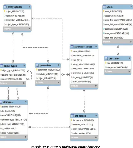
[image:3.612.316.540.96.209.2] [image:3.612.315.540.278.397.2]The database structure developed for storage of a meta model contains 8 tables and is provided in a Figure-1.
Figure-1. Database structure.
We will consider in more detail each table and its assignment.
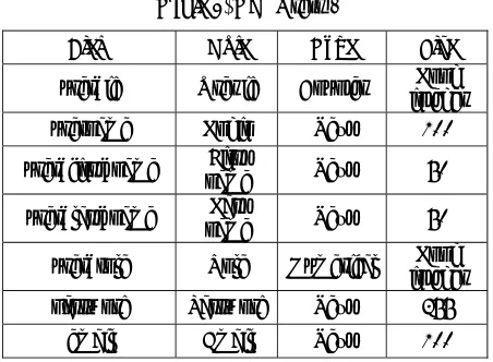
The table "Objects entity" (entity objects) serves for storage of objects of system. It is connected to the tables "Object Types", "Parameters", "Parameter values". Fields of the Table "Objects entity" are provided in Table-1.
Table-1. Table DB "Objects entity".
Field Role Type Size
object_id Object ID Counter integer Long
name Name Text 100
description Description Text 1000
object_type_id
Identifier of object
type Numerical
Long integer
The table "Object Types" (object types) serves for storage of object types of system. It is connected to the table "Attributes". Fields of the table "Object Types" are provided in Table-2.
Table 2. DB "Object types".
Field Role Type Size
object_type_id Identifier of the object
Counter Long integer
name Name Text 100
parent_type_id
Identifier of object
type ancestor
Numeric
al integer Long
[image:3.612.79.295.312.552.2]The table "Attributes" (attributes) serves for storage of attributes. It is connected to the table "Object Types", "Parameters", "List-oriented Values". Fields of the table "Attributes" are provided in Table-3.
Table-3. DB "Attributes".
Field Role Type Size
attribute_id Attribute identifier Counter integer Long
name Name Text 100
attr_type Attribute type Numerical Integer
reference_type_id
Object type to which
this attribute can refer
Numerical integer Long
object_type_id
Object type to which attribute belongs
Numerical integer Long
is multiple whether Is multiple Boolean
order number Sequence number Numerical Integer
[image:3.612.316.540.473.697.2] [image:3.612.316.540.477.695.2]"Attributes", "Object Types" and "Parameter values". Fields of the table "Parameters" are provided in Table-4.
Table-4. DB "Parameters".
Field Role Type Size
parameter_id Parameter identifier Counter integer Long
attribute_id Attribute identifier Numerical integer Long
object_id identifier Object Numerical integer Long
The table "Parameter values" (parameter values) serves for storage of parameter values. It is connected to the table "Objects Entity", "Parameters", "List-oriented Values". Fields of the table "Parameter values" are provided in Table-5.
Table-5. DB "Parameter values".
Field Role Type Size
value_id Identifier of the
Counter Counter Long integer
parameter_id
Identifier of
parameter Numerical Long integer type Whole Type Numerical Integer
string_value String Text 500
date_value Date Date
reference_id Object ID Numerical Long integer
list_entry_id
Identifier of list-oriented
value
Numerical Long integer
order number Sequence number Numerical Integer
[image:4.612.315.541.178.344.2]The Table "List-oriented Values" (list entries) serves for storage of list-oriented values. It is connected to the table "Attributes" and "Parameter values". Fields of the table "List-oriented Values" are provided in Table-6.
Table-6. DB "List-oriented values".
Field Role Type Size
list_entry_id
Identifier of the list-oriented
value
Counter integer Long
attribute_id Identifier of attribute Numerical integer Long
entry_value Value Text 100
order number Sequence number Numerical Integer
These tables provide storage of a meta model in the database. In addition to them in system 2 plane tables for information storage about users of the application are used.
The table "Users" (users) serves for data storage about users. It is connected to the table "Roles". Fields of the table users are provided in Table-7.
Table-7. DB "Users".
Field Role Type Size
user_id User id Counter integer Long
username Login Text 100
user_first_name name First Text 50
user_last_name Last
name Text 50
user_role Role Numerical integer Long
password Password Text 255
email Email Text 100
[image:4.612.315.539.410.466.2]The table "User Roles" (user_roles) serves for data storage about roles of users. Fields of the table "User Roles" are provided in Table-8.
Table-8. DB "User roles".
Field Role Type Size
role_id Identifier Role Counter integer Long
name Name Text 255
3.3. A data model for operation with storable classes entities
Features of implementation of Java Persistence API impose restrictions for operation with classes entities. Life cycle of entity of JPA consists of 4 statuses: new/transient (new), managed (controlled), removed (remote) and detached (unfixed). At the same time in each time point the entity can be only in one of them. In a Figure-2 life cycle of JPA entity and transitions between statuses is provided.
[image:4.612.75.539.599.727.2]Set of the entities which are in a controlled status (managed) make a so-called context of saving (Persistence Context). He acts only within one transaction then all entities which are contained in it pass into the unfixed status (detached). In this status the entity can have not loaded fields if they are marked as loaded upon the demand of (fetch = with LAZY). Also JPA doesn't monitor change of the entities which are in the unfixed status, and, therefore, such changes won't be recorded in the database.
In the meta model developed for this application loading of fields on demand for abbreviation of consuming of memory and the data volume circulating between a DB and application widely is used. Therefore in order to avoid problems with receiving the field values loaded on demand at the entities which are in the unfixed status the decision to use additional model and a set of services for conversion of this model to controlled entities of JPA is made. Such decision will allow to have an idea of entity with a set of parameters necessary at present, without transferring excess information on the client. Need of these or those data is generally dictated by the presentation layer and depends on what information is required for display.
The class diagram of the developed model is given in a Figure-3.
Figure-3. Class diagram of model.
Each class of this model serves for information transfer on the presentation layer and considers need for specific information for certain elements and pages of the web application. For example, the class "HierarchicalObjectTypeModel" serves for creation of a tree of object types. In this context we need to know the identifier of object type, his name and the ancestor, but information on attributes isn't necessary. In case of a choice in a tree of any element, it is necessary to provide information output about attributes, and the class successor "Hierarchical Object Type With Attributes Model " which has necessary data for this purpose is already used. Proceeding from the same reasons, also remaining classes of model were designed.
Work is carried out with classes entities in special services. Their methods work in transactions that guarantees finding of entities in a controlled status and correct operation of loading of fields on demand. These services accept and the objects of model used at the business logic layers and representations return.
The following services were developed for use in system:
Object Types Service for operation with object types;
Attribute Service for operation with attributes;
Parameters Service for operation with parameters;
Parameter Values Service for operation with parameter values;
Objects Service for operation with objects;
User Service for operation with accounting entries of users.
Services realize the following functionality:
creation of controlled entities on model;
receiving models on the entity identifier;
modification of entity according to model.
4. BUSINESS LOGIC LAYER
The business logic is a rule set of behavior of entities of a certain data domain. The layer of business logic of application is realized by means of JSF Managed Beans or bins - Java of classes which are under control of a container framework (Java EE application server). JSF components of the presentation layer can get directly access to fields and methods of a bin. Most often JSF Managed Beans are used for such purposes as:
verification of the data entered into a JSF component;
event handling of a component;
determination of the page to which application shall transfer.
The application server controls life cycle of a bin, and each bin has one of the following areas of existence:
application scope - a copy of a bin exists throughout operation of application;
session scope - a copy exists throughout session of the user;
view scope-a copy is created in case of the addressing the page and exists until the user on it is.
We will consider the organization of a layer of business logic on the example of the class which is responsible for operation of a panel of the administrator.
This class is a wrapper over two other managed classes which are responsible for display of a tree of object types – Object Types Tree Bean and information on attributes of object type – Object Type View Bean. Such approach is caused need of processing of an event of a choice of object type for a tree both for him, and for the class which is responsible for display of attributes. The wrapper receives the event notification and causes methods processors in Object Types Tree Bean and Object Type View Bean. The desire to have an opportunity to pereispolzovat these components for other pages is one more reason of use of this mechanism. The tree of object types is also used for the page which works with objects, at the same time it isn't necessary to duplicate a code.
These classes are marked by the summary "@View Scoped" and their copies exist while the user is on the page.
5. REPRESENTATION LAYER
The layer of representation is realized by means of Java Server Faces (JSF) - a platform for creation of the user interface of the web applications written in the Java language and library the Prime Faces 5.2 JSF component.
The following web pages were developed for interaction of the user with system:
page of authentication "Login";
page of editing meta model "Administrator's panel";
page of control of accounting entries of the Users system;
the page for operation with objects of system.
For the organization of input and display the following JSF components of Prime Faces library were used:
tables (dataTable);
data entry fields (inputText);
toolbars (toolbar);
buttons (command Button );
dialogs (dialog);
tooltip balloons (tooltip).
Operation with a meta model is the most interesting part of system and is carried out by means of the page of the editor of a meta model. It contains a tree of object types and the table for display of attributes for the selected object type. Here it is possible to create new object types, to view, add and delete attributes. From this page transition to the page of user account control is carried out.
When clicking the Create button there will be a dialog box in which it is necessary to enter a name of new object type. In case of confirmation of creation of object type the tree of object types will be updated.
6. ALGORITHMIC AND SOFTWARE OF
PROCESSING OF INPUT DATA AND CONTROL OF FLOWS
The developed program components represent reflection of class model concerning the class ancestor IMy Interface according to the architecture of inheritance provided in a Figure-4.
Mechanisms of inter modular interaction are constructed on interfaces of the created components. At first there is an analysis of input information, parse of request, monitoring of operability of inter modular communications, and procedure of interaction according to the algorithm provided in a figure 5 is launched only then.
In a Figure-6 the skeleton diagram of the software of the server is provided. It consists of the following components.
6.1 Human-computer interaction component
After arrival of start information and the first phase of inter modular interaction the virtual link between modules of service of request and its processing on the server is dynamically realized. This channel is created for all the time of execution of request up to receiving by a response source from the server with use of descendants of the basic IMy interface.
Figure-5. Diagram of a data interchange.
Figure-6. Architecture of the server software.
6.2 Server service of jobs
The server accepts the job from a source in a type of text and string information. This information is decompiled. The decompiling purpose - partition of the job on operators and arguments.
After partition of the job on operators and arguments the set of binary relations in which search of key words operators is carried out is had. The second element of the relation identified thus is an argument of the operator. After completion of procedure of binary identification the server launches dynamically loaded module of service of the operator of language.
We will analyze algorithms of operation of components of the decompiled job. Selection of My Select starts with attempt of communication of the pointerful server, contained in the second element of the binary relation.
If attempt of communication is rejected, the source obtains information on unavailability of object and need of correction of request.
If attempt of communication is successful, cyclic processing of all components of the decompiled job is launched. In case of successful comparing the result of the job is created and goes to a source.
Adding of My Insert is also realized from attempt of communication of the pointer full server, contained in the second element of the binary relation.
If attempt of communication is rejected, the source obtains information on unavailability of object and need of correction of request.
If attempt of communication is successful, cyclic processing of all components of the decompiled job is launched. In case of successful comparing the result of the job is created and goes to a source.
The reduction of My Delete is similarly realized from attempt of communication of the pointer full server, contained in the second element of the binary relation.
If attempt of communication is rejected, the source obtains information on unavailability of object and need of correction of request.
If attempt of communication is successful, cyclic processing of all components of the decompiled job is launched. In case of successful comparing the result of the job is created and goes to a source.
7. CONCLUSIONS
The cross-platform web application which will provide users with the flexible tool for storage of an object model of arbitrary data domain is result.
For achievement of the end result a row of tasks is solved: the chart of options of use of system is developed;
the object meta model in the Java language is developed;
the database for storage of a meta model and information on users is designed;
the user interface by means of the JSF technology is created;
The stage of programming was carried out with use of a development environment of NetBeans, for data storage MySQL DBMS is used.
REFERENCES
[1] Barroso L. and Holzle U. 2009. The datacenter as a computer: An introduction to the design of warehouse-scale machines. Synthesis Lectures on Computer Architecture, vol. 4, no. 1, pp. 1-108.
[2] Chaudhry S. et al. 2005. High-performance
throughput computing. Micro, IEEE, vol. 25, no.3, pp. 32-45.
[3] Frigyik, B.A., Kapila, A. & Gupta, M.R. 2010. Introduction to the Dirichlet distribution and related processes. UWEE, Tech. Rep. UWEETR-2010-0006.
[4] Hoang Zhang and Kravets O.Ja. 2015. About convergence of scalable Markov process to the determined dynamic system with unique equilibrium point. Advanced models and technologies in computer networks: Proceedings of the International scientific and practical conference (Yelm, WA, USA, 06 July 2015). Editor in Chief Dr. Sci., Prof. O.Ja. Kravets. Yelm, WA, USA: Science Book Publishing House. pp. 101-111.
[5] Hoelzle U. et al. 2009. The Datacenter as a Computer:
an Introduction to the Design of Warehouse-Scale Machines. - 1st. Morgan and Claypool Publishers.
[6] Khoang Zhang and Kravets O.Ja. 2015. Identification and the characteristic of data-centers operational loads on the basis of the computing paradigm oriented on throughput. Modern informatization problems in economics and safety: Proceedings of the XX-th International Open Science Conference (Yelm, WA, USA, January 2015). Editor in Chief Dr. Sci., Prof. O.Ja. Kravets. Yelm, WA, USA: Science Book Publishing House. pp. 85-93.
[7] Kravets O.Ja. 2013. Mathematical Modeling of Parametrized TCP Protocol. Automation and Remote Control. 74(7): 1218-1224.
[8] Kravets O.Ja. and Oleinikova S.A. 2014. Multiagent technology for the application of a distributing function for load balancing in multiserver systems. Automation and Remote Control. 75(5): 977-982.
[9] Kravets O.Ya., Makarov O.Yu., Oleinikova S.A., Pitolin V.M. and Choporov O.N. 2013. Switching
operational annunciator and monitoring systems: program design features. Automation and Remote Control. 74(11): 1919-1925.
[10]Sang B., Zhan J., Lu G., Wang H., Xu D., Wang L., Zhang Z. and Jia, Z. 2012. Precise, scalable, and online request tracing for multitier services of black boxes. IEEE Transactions on Parallel and Distributed Systems. 23(6): 1159-1167.