Multiagent voltage and reactive power control system
Arkhipov I.
1, Molskij A.
1, Ivanov A.
2, Novickij D.
2, Sorokin D.
2, Holkin D.
21
Federal Grid Company of Unified Energy System (FGC UES), OJSC
22/3, Kashirskoe shosse, Moscow, Russia, 115201
2 R&D Center at Federal Grid Company of FGC UES (R&D Center at FGC UES), OJSC 5A, Akademika Chelomeja street, Moscow, Russia, 117630
Abstract
This paper is devoted to the research of multiagent voltage and reactive power control system development. The prototype of the system has been developed by R&D Center at FGC UES (Russia). The control system architecture is based on the innovative multiagent system theory application that leads to the achievement of several significant advantages (in comparison to traditional control systems implementation) such as control system efficiency enhancement, control system survivability and cyber security.
Keywords: Multiagent systems, Smart Grid, intelligent power systems, voltage and reactive power flow control, active power losses. Received on 12 August 2014, accepted on 02 September 2014, published on 12 December 2014.
Copyright © 2014 Arkhipov I et al., licensed to ICST. This is an open access article distributed under the terms of the Creative Commons Attribution licence (http://creativecommons.org/licenses/by/3.0/), which permits unlimited use, distribution and reproduction in any medium so long as the original work is properly cited.
doi: 10.4108/ew.1.3.e3
1. Introduction
Due to rise of distributed generation, emergence of so-called active consumers, development of microgrids, hybrid/electric transportation and other factors power system is getting more and more complex. Being a System of Systems, now it provides possibility of an autonomous and independent functioning and development of individual subsystems. At the same time, there is a tendency of joining autonomous power systems in the unified power system. Transformation of the power industry is associated with changes in the entire energy conversion process (from production to consumption), including the power section, information and control subsystems and the relationships between the business entities. It should be stressed that at the current stage of the power industry development the key changes in the industry are performed to reengineer the power system control and business processes based on the intensive use of modern information and communication technologies, including various power automation solutions, sensors, FACTS (flexible alternating current transmission system) devices, etc.
Being a key infrastructure element of the power system electric grids should be adapted to changes in a first place. To meet new requirements the electric grids should be controlled (to a greater extent than nowadays) to increase
power transfer capability and also be customer-oriented and self-organizing. Electrical grid that is met the requirements is known as Smart Grid [1, 2, 3]. The grid is considered to be a part of intelligent power system [4, 5]. Investigation of Smart Grid development, implementation and commissioning in Russian electrical grids was initiated by Federal Grid Company of Unified Energy System (FGC UES*). In particular FGC UES had organized in 2009 following studies:
development of the Smart Grid Reference Architecture for Russian power system;
development of new generation power control system prototypes;
testing of complex technical solutions within selected pilot Smart Grid areas.
Pilot Smart Grid area chosen by FGS UES to implement a new generation power control system prototype was Elgaugol intelligent grid cluster.
The cluster is located in the south-eastern part of the Sakha (Yakutia) Republic and encompasses northern part of the Amurskaja region.
Construction and commissioning of new electric grid infrastructure in this area is necessary to provide energy
*
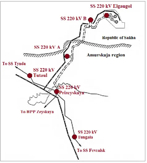
supply of Elga coal deposit. The electrical network of the cluster is shown in Fig. 1.
Figure 1.The electrical network of the intelligent cluster
During the construction and commissioning of the cluster infrastructure the new substations and one existing substation (that is in operation nowadays) will be equipped with an innovative decentralized control system – automated multiagent system of voltage and reactive power control (MAS V&R) that is being constructed on the base of multiagent systems theory application. The studies are a part of the FGS UES`s Smart Grid development program for the Unified Power System of the East Russia† [6]. The project is being designed and developed by R&D Center at FGC UES.
2. Smart Grid Reference Architecture
During 2012-2013 under the auspices of the Architecture Committee (a body of the Joint FGC UES – Russian Academy of Sciences Science and Technical Council), seven expert working groups developed basic provisions and approaches to the implementation of the Smart Grid Reference Architecture – SGRA [7].
† Unified Power System of the East Russia is one of six major
subsystems of Russian national Unified Power System, and encompasses several regions of Russian Siberia and Far East.
All groups were conventionally classified in two types. Four groups of the 1st type represented the interests of the different power system entities:
Transmission and distribution;
Large power generation companies and consumers;
Distributed generation, energy storage and renewable energy sources;
Small consumers, retail companies and service providers.
Remaining three groups (2nd type) represented different forms of power system control and management, including:
Market mechanisms;
Power system control;
Information and communication technologies.
2.1. Requirements for the grid infrastructure
development
The tasks of the groups of 1st type were development of scenarios to elaborate efficient use cases of the intelligent power system and define requirements for Smart Grid on behalf of above mentioned stakeholders.
During this process, that involved intensive group discussions about future power system development visions, it appeared that views of different stakeholders were in many important cases significantly different and in some cases even mutually exclusive. For example, largest power generation companies and biggest consumers in the first place need to ensure the reliability of the power system and the ability to maximize the use of their productive assets. On the other hand, for dynamic developing companies, that do not refer to the resource extraction or primary procession the key requirement was fast connection to the electrical grid to begin production as soon as possible.
These differences are rooted in respective stakeholder`s economic and business-model specifics. As for abovementioned examples, large industrial business entities (both generators and consumers) in general represents moderate-growing, capital-intensive industries operating on highly competitive markets. Not surprisingly that efficiency is a significant competitive advantage for them and they expect intellectualization to provide new possibilities for economising.
Vice versa, for dynamic, high-growth enterprises from non-resource sectors power expenses do not constitute significant part of their products costs. But affordability of power and services are in first place – especially in the realm of more durable administrative processes in Russia. In the case of some high-tech industries, higher power quality is also among key requirements.
to support and motivate consumers to be active participants in power systems;
to ensure the quality of electricity that meets the requirements of the high-tech economy;
to make easy grid integration of all types of power systems, equipment, devices and services (distributed generation, energy storage, resistive load, etc.) ;
to optimize use of assets on the side of electric grids and other business entities;
to develop new electricity markets and services for different groups of consumers;
to accelerate and reduce costs of the development, production, and operation of control systems.
2.1. Main architectural design decisions and
their applications
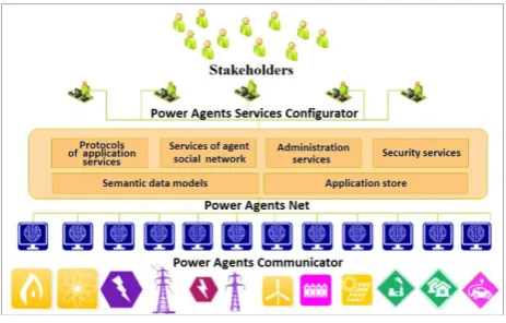
Analysis of the requirements developed by the working groups and study of best practices [8, 9] made it possible to determine some basic architectural decisions. These decisions formed the foundation of the architectural template – Power Agents Architect Template Reference Architecture (Fig. 2).
Figure 2.Power Agents Architect Template
In particular, these decisions include: multiagent approach to control, semantic approach to working with data, modular platform with an open architecture, "social network" of agents, configurator of business services. According to the architectural decisions the basic logic of control system implementation and business process management consist of the following theses:
The object of control must be equipped with sensors for gathering information in the real-time mode such as status of the system, status of the equipment, state of the environment, etc.
Each object of control must be equipped with the intelligent multiservice communicator (Power Agents Communicator) with agent-based software which processes the local information, performs a variety of services (including services that produce control actions), and interacts with other communicators.
Control signals obtained by Power Agents Communicator are sent to the equipment control systems.
Agents are participants of the specialized social network (Power Agents Net) which provides the interaction between agents and additional system services.
Higher-level dispatch and control centres (for example, electrical grid control centre, dispatch power system centre, group control centre for several substations, etc.) and possibly specialized service companies use the software (Power Agents Services Configurator) to configure control systems in accordance with the requirements of the stakeholders, to monitor the control system operation, to have the opportunity to turn the control system in manual mode (if it is necessary).
These theses formed architectural basis for the intelligent power control system development. On the first stage this system allows to control voltage and reactive power flows in the electrical networks. At the following stages the system will be equipped with additional modules (agents) to implement additional functions without system’s reengineering. Composition and number of the modules are now being agreed.
3. System requirements for the voltage
and reactive power control system
3.1. Requirements relating to the functional
destination of the system
Basic requirements for the voltage and reactive power control system are associated with its main functional destination – to ensure the stabilization of the voltage levels and the reduction of active power losses. Efficiency of meetingthese requirements is defined by the possibility to reduce:
amount of active power losses in the energy cluster by 5%;
3.2. Adaptability of the control system
One of the key requirements for the control system is the need to provide the functioning of the control system in cases of significant changes in power system mode. These changes can be caused by power system switching operations at substations or power plants, power system disturbances and also commissioning of new power system equipment (including controlled equipment). In particular, the duration of new equipment integration to the control system should be no more than one minute (after putting equipment into operation). For the purpose of this study R&D Center of FGC UES defined new equipment as special electrical equipment (such as reactive power compensation devices, synchronous generators, etc.) or automatic control systems.
3.3. Control system functionality during
communication channels damages
Another key requirement of the control system is the need to preserve basic functionality of the control system in cases of communication channels damage between grid elements (substations). Technological disturbances during the process of information transmission via communication channels may be due not only to technical reasons (for example, communication equipment failures) but also targeted third-party interference in the channels. Fulfilment of this requirement means supporting control system performance in case of possible interferences in communication channels - including unacceptable delay occurrences, loss of some or complete loss of transmitted data (loss of communication channel) with one or more electric grid elements. Preserving control system performance in such cases is possible when the distributed (decentralized) control and data storage logic is used in the control system.
3.4. Reduced cost of the control system
construction, commissioning and operation
Another important requirement is the reduction of costs for control system construction, commissioning and operation. Open and modular control system architecture allows additional functionality (additional modules) in the existing control system. It is possible not only on the construction stage, but also during the system operation. Such architecture allows to develop new functional modules by different manufacturers (companies). New modules can be automatically integrated into the infrastructure of control system without long periods of control system redesigning and decommissioning. The quantitative criterion that defines the upper limit of the cost of the control system implementation for power plants (substations) was proposed. This criterion implementation will create the preconditions for commissioning the intelligent control systems in
industrial quantities. This criterion is the following: cost of putting into operation of the control system should not exceed 1% of the power equipment cost of the power system object (in which the control system is put into operation).
Multiagent approach for the control system allows to meet all the requirements considered, making possible to implement distributed power system control, increasing intelligence of the automated functions, and usage of dynamic modularity and self-management systems.
4. The architecture of multiagent control
systems
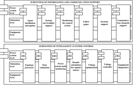
Application of the MAS concept (as well as algorithms for multiagent power system control) makes it possible to construct the architecture in which a definite functionality of the system is implemented by a separate stand-alone subsystem – agent (or agent network if the implementation of this function requires functioning of several agents). The block diagram of the multiagent automated MAS V&R power control is represented in Fig. 3.
Figure 3.The block diagram of the multiagent automated system of voltage and reactive power
control
From the Fig. 3 it can be seen that an automated control system consists of two major subsystems – technological control subsystem, and information and communication subsystem. Technological control subsystem includes agents that implement voltage and reactive power control in the electrical grid. Information and communication subsystem includes agents that support system functioning. In particular, the information and communication subsystem includes agents that provide the possibility of:
adding to the control system some new functionality (new agents);
preserving control system performance during technological malfunctions (e.g., switching devices failure);
SUBSYSTEM OF INFORMATION AND COMMUNICATION SUPPORT
automatic integration of new electrical equipment to the control loop of the automated system, etc.
Each subsystem contains multiagent groups that unite agents of different destination and different control levels in the social network. For each agent group a common ontology and communication protocols are used. In terms of expansion and development of the control system, proposed architecture allows to add agent (or agent group) to each subsystem in order to implement new system functionality.
In terms of control system operation, the system division into groups allows to define specialized agent that coordinates group functioning and can be used to provide user interface for MAS V&R. Application of this interface allows users to configure the control system, including changing agents purposes in the groups, as well as methods of decision-making in agent interaction process.
5. Description of multiagent automated
system of voltage and reactive power
control
5.1. Description of the controlled object
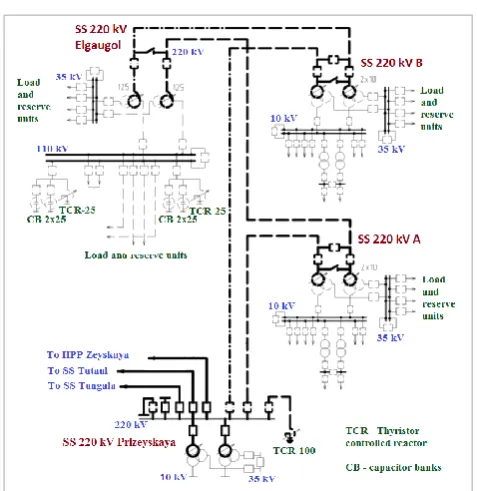
As it was mentioned earlier, FGC UES`s R&D Center develops automated MAS V&R control for the pilot energy cluster Elgaugol. The cluster includes two transmission lines of 220 kV from Prizeyskaya substation (in Amurskaja region power system) to Elgaugol substation (in Republic of Sakha power system). Transmission lines connecting Prizeyskaya and Elgaugol substations supply with power A and B substations that are situated at distance of approximately 100 km and 200 km respectively from the Prizeyskaya substation. Single line diagram of the electrical connections of the energy cluster Elgaugol (in accordance with current project documentation) is shown in Fig. 4.
According to the project documentation the autotransformers with on load tap changer devices and two groups of reactive power compensation devices are planned to be installed at Elgaugol substation. Each group of the reactive power compensation devices is connected to the bus section 110 kV of substation Elgaugol and includes one thyristor controlled reactor 50 Mvar and two switched static capacitors 25 Mvar.
At the substation Prizeyskaya there are one thyristor controlled reactor 100 Mvar and two shunt reactors 25 Mvar. The thyristor controlled reactor is connected to 220 kV buses, the shunt reactors are connected to 35 kV buses.
Figure 4.
Single line diagram of electrical
connections of the intelligent cluster
5.2. Control loops of the automated system
There are two basic operation modes of MAS V&R control. Both modes are cyclic with different time loop durations: slower optimization mode and faster control mode.
In a slower optimization mode the control system operation can be configured to periodical or sporadic cycle. In the periodical cycle the optimization is run periodically at regular time intervals (from several seconds to minutes). In the sporadic cycle the optimization is run by the command from agents. As a result of the optimization the optimal voltage levels on the buses 220 kV in the network, optimal transformer (autotransformers) ratios and optimal compensation devices settings are determined to achieve a minimum value of the chosen objective function (which is used in optimization procedure). In a slower optimization mode different objective functions can be set: reduction of power and energy losses in the electric networks or improvement of the voltage level stabilization in the network (decreasing voltage deviations from the specified values). In addition there is optimization mode (hybrid mode) that minimizes both power losses (objective function #1) and the voltage deviations from the specified values (objective function #2). In this mode the weight and penalty coefficients are used to determine the priority of achieving the minimum of different objective functions.
The faster mode has also options for the flexible configuration and changing settings. Objective functions in the faster mode may be the energy losses minimization in the power equipment or (and) reduction the number of switching cycles of static capacitors and shunt reactors. The choice of the objective function is possible in user interfaces provided by coordinator agents.
5.3. Control cycles of the multiagent control
system
To provide automatic adaptation of the control system to power system mode changes or to the commissioning of new power equipment, multiagent concept of the system configuration is used [10, 11, 12]. This concept is based on the fact that each element of the power system is represented with its equipment agent. These agents are a part of the diagnostics equipment agent group and are on the lower level of the functional subsystem – hardware level. It should be noted that multiagent concept have proved the efficiency application in power systems [13, 14, 15, 16, 17, 18].
Each equipment agent contains a description of its elements in form of CIM (RDF) file in accordance with the Common Information Model (IEC 61970-301) [19, 20]. The details of the network representation in agents correspond to the details of the class diagram in CIM model. In addition to the specified attributes the equipment agents also include information about local measurements and possible control actions in the format of IEC 61970 and IEC 61850 [21].
In the future this approach will provide the integration of control system with monitoring and diagnostic systems for transmission through the equipment agent information about technical condition of equipment. In this case it will be sufficient to replace program code of corresponding equipment agent without changing system`s basic code (platform).
When commissioning new power system equipment (up to the moment of its connecting to the grid) its owner provides necessary equipment information to register the equipment agent. During registering, equipment agent informs “yellow pages” agent about new equipment appearance in the grid and transmits to “yellow pages” agent date and time of new equipment commissioning. The yellow pages agent notifies topology agents that are signed to the specified event.
The topology agent provides addition of new element to the topological model (graph) of the electric grid. Later on, topology agents based on local power system parameter measurements and breakers` states creates a calculation model of the grid. From this moment the equipment is presented in the MAS infrastructure and will be considered in the optimization calculations (when the equipment is in operation). Calculation model is obtained based on the power system state estimation procedure. During the state estimation there is a possibility to check the plausibility of information (measurements and breaker
states) received from the adjacent substations (power plants) and to restore the missing or implausible data. The state estimation can also be used to restore missing information in cases of communication channel failure. Nowadays wide-area measurement systems (WAMS) are being commissioned that allows to use highly accurate data provided by these systems for missing data restoring and for predicting power system parameter change trajectory [22, 23]. After electric grid computational model is available, restrictor agents define the boundary values for optimization procedure of power system parameters. These boundary values are determined by the upper-level systems (e.g., a dispatching centre).
Further optimization agents calculate optimal values of voltages and ratio of transformer (autotransformer) and transmit these values to control agents. Control agents determine optimal control laws of reactive power change (for equipment units which are under its control) and monitor that the power system achieves the optimal state. This control cycle in general is similar to the SCADA/EMS one [24, 25]. However there is a significant difference: control cycle in the MAS is performed at each substation, control signals between substations are not transmitted and the coordination of different controlled element operation is achieved by means of the multiagent control principles. It should be also mentioned that each substation can use their own network model that can differ from the models of other substations.
5.4. New opportunities provided by MAS
V&P control
Depending on the settings of the coordinator agent the system operation efficiency may vary over a wide range. Coordinator agents’ settings can define different parts (bounds) of the grid to optimize and control that can lead to a different control system’s behaviour and a different system’s efficiency.
If state of the grid estimation is performed using accurate measurements (for example provided by WAMS), network models that are formed by the agents of different substations will be practically matched. If all optimization agents use the same objective functions then each substation will have the same “idea” of the optimal system state. In this extreme case the MAS performance is similar to the performance of centralized control systems.
In other extreme case when only local measurements and signals are available at each substation, MAS performance is similar to the performance of independently acting local regulator groups.
MAS architecture and possibilities of energy cluster Elgaugol allow to implement both extreme cases. Determination of optimal balance between centralized and local control and development of best mode of regulation is one of the pilot project objectives.
architecture provides new opportunities for a variety of directions:
• use of power reserves to improve accessibility for grid connection and ensuring reliability of power supply to consumers.
• opportunities to implement adaptive emergency control and relay protection devices. Implementation of these functions is an urgent task that is necessary to ensure high level of selectivity and sensitivity of protection devices and to reduce risks of improper "manual" selection of protection settings in electric grids. • given the ability to scale up and phasing of MAS
development it is promising to create on the basis of MAS a number of specialized products and services for new or extended opportunities for power industry business entities. Among them are acquiring different real-time information related to energy equipment, power quality and power losses, etc. These new possibilities will allow to organize system service market in power system in the most efficient way.
The advantage of MAS in comparison to existing traditional centralized systems is also significantly higher levels of cyber security and reliability of multiagent automated systems. This is due to ability of MAS to perform autonomous operation of different system elements and high levels of MAS reliability in cases of shortage of plausible measurement data.
6. Conclusion
MAS V&P control prototype has been developed by R&D Center at FGC UES. This prototype is planned for testing by real-time digital simulators of power system with consequent installation in the Elgaugol cluster. This project is aimed both on creating new systems for practical needs of Elgaugol and Russian UES of East and getting experience of configuration and operation of multi-agent systems.
Development and usage if MAS V&P control system will:
form the basis for a phased increase in the functionality of control systems of electrical networks;
create preconditions for wider use of ancillary services in the power industry;
enable the formation and development of the market for Smart Energy applications;
contribute to power supply reliability improvement.
Application and further development of the multiagent approach in power system control will enable phased "intellectualization" of the electric grid infrastructure and create conditions for the new competitive market
applications foundation, enhance the efficiency of the new technologies application.
References
[1] Federal Smart Grid website (http://www.smartgrid.gov/) [2] L.T. Berger, K. Iniewski, “Smart Grid Applications,
Communications, and Security”, Wiley, 2012.
[3] A. Feliachi, R. Belkacemi, “Intelligent Multi-agent System for Smart Grid Power Management”, Springer, 2012. [4] J.R. McDonald, S. McArthur, G. Burt, J. Zielinski,
“Intelligent knowledge based systems in electrical power engineering”, Springer, 1997.
[5] H. Bevrani, T. Hiyama. “Intelligent Automatic Generation Control”, CRC Press, 2011.
[6] Modernization through the development of innovative – the creation of an intelligent network. Report of FGC UES (http://www.fsk-ees.ru/media/File/press_centre/speeches/ Presentation_Budargin_26.10.10.pdf)
[7] Basic concept of Smart Grid with active-adaptive network (http://www.fsk-ees.ru/upload/docs/ies_aas.pdf).
[8] Methodical approach to the development of reference architecture of intelligent power system with active-adaptive network (http://gridology.ru/).
[9] D. Holkin, D. Novickij, A. Ivanov, D. Sorokin, “Innovative development of Russian electrical networks based on Smart Grid implementation”, Prospects for the development of electric power and high voltage electrical equipment. Energy efficiency and conservation (XVIII Conference of the International Association of Business Cooperation TRAVEK), Moscow, 2014.
[10] Wooldridge M., “An Introduction to Multi-Agent Systems”, Wiley, 2002.
[11] S.D.J. McArthur, E.M. Davidson, V.M. Catterson, A.L. Dimeas, N.D. Hatziargyriou, F. Ponci, T. Funabashi, “Multi-Agent Systems for Power Engineering Applications – Part I: Concepts, Approaches, and Technical challenges”, IEEE Transactions On Power Systems, vol. 22, no. 4, 2007.
[12] S.D.J. McArthur, E.M. Davidson, V.M. Catterson, A.L. Dimeas, N.D. Hatziargyriou, F. Ponci, T. Funabashi, “Multi-Agent Systems for Power Engineering Applications – Part II: Technologies, Standards, and Tools for Building Multi-agent Systems”, IEEE Transactions On Power Systems, vol. 22, no. 4, 2007.
[13] J. Solanki, S. Khushalani, N. Schulz, "A multi-agent solution to distribution systems restoration", IEEE Trans. Power Syst., vol. 22, no. 3, pp.1026-1034, 2007.
[14] J. Kodama, T. Hamagami, H. Shinji, T. Tanabe, T. Funabashi, H. Hirata, “Multi-agent-based autonomous power distribution network restoration using contract net protocol”, Elect. Eng. Japan, vol. 166, no. 4, pp. 56-63, 2009.
[15] H. Wedde, S. Lehnhoff, E. Handschin, O. Krause, “ Real-time multi-agent support for decentralized management of electric power”, Proc. 18th EUROMICRO Conf. Real-time systems, pp. 9, 2006.
[16] C. Lin, C. Chen, T. Ku, C. Tsai, C. Ho, “A multiagent-based distribution automation system for service restoration of fault contingencies”, Eur. Trans. Elect. Power, vol. 21, no. 1, pp. 239-253, 2011.
Multi-agent System, Control and Decision”, vol. 18, no. 3, pp. 371-374, 2003.
[18] A. Vaccaro , G. Velotto and A. Zobaa, “A decentralized and cooperative architecture for optimal voltage regulation in smart grids”, IEEE Trans. Ind. Electron., vol. 58, no. 10, pp. 4593-4602, 2011.
[19] IEC 61970, Common Information Model (CIM) / Energy Management.
[20] D.J. Abadi, A. Marcus, S.R. Madden, K. Hollenbach, “SW-Store: A Vertically Partitioned DBMS for Semantic Web Data Management”, VLDB Journal, 18(2), April, 2009.
[21] IEC 61850, Power Utility Automation.
[22] G. Phadke, J.S. Thorp, “Synchronized Phasor Measurements and Their Applications”, Springer, 2008. [23] V. Terzija, G. Valverde, C. Deyu, P. Regulski, V. Madani ,
J. Fitch, S. Skok, M.M. Begovic, A. Phadke, “Wide-area monitoring, protection, and control of future electric power networks”, Proc. IEEE, vol. 99, no. 1, pp. 80-93, 2011. [24] D.J. Gaushell, W.R. Block, "SCADA Communication
Techniques and Standards", IEEE Computer Applications in Power, 1993