EAGLE-EYE: A DUAL-PTZ-CAMERA SYSTEM FOR TARGET
TRACKING IN A LARGE OPEN AREA
Hsien-Chou Liao, Wei-Yi Chen
Chaoyang University of Technology, Department of Computer Science and Information Engineering 168 Jifong E. Rd., Wufong Township Taichung County, 41349, Taiwan (R.O.C.)
e-mail: [email protected], [email protected]
Abstract. An active camera, i.e., pan-tilt-zoom (PTZ) camera, can be used either to monitor a wide area or capture a high resolution image of a specific object by adjusting the zoom value. In order to achieve the above two goals simultaneously just like an eagle’s eye, a novel dual–PTZ-camera system, called Eagle-Eye, is proposed in this paper. The system can keep monitoring the whole area while tracking and focusing on the details of an object. Two techniques, moving object detection and fuzzy matching, are used alternatively for target tracking. According to the experimental results obtained with the implemented prototype, the success rates of tracking tasks for various moving speeds during daytime and nighttime are about 90 percent. The success rate with occlusion condition is also more than 80 percent. Furthermore, the average success rates with four special moving paths are 83.8 percent. These results show that Eagle-Eye system is feasible and achieves good tracking performance under various conditions.
Keywords: IP surveillance system, camera control, motion detection, object tracking.
1. Introduction
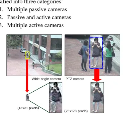
Digital surveillance systems are used ubiquitously, especially in urban areas. The real-time image and recorded videos can be used for various services, such as security, elder health care, optical inspection [1], fire detection [2], and so on. The cameras used in surveillance systems can be classified into two types: passive or active. A passive camera has a fixed zoom. Its field-of-view (FOV) is also limited. Multiple pas-sive cameras are usually used to cover the whole sur-veillance area. Conversely, an active camera can pan and tilt to a desired position and zoom in on inte-resting objects. It can be used to monitor a large open area. It is also called a pan-tilt-zoom (PTZ) camera. Many studies attempt to utilize PTZ cameras for pro-viding new surveillance services. For example, a PTZ camera can incorporate a passive camera and become a dual-camera system [3-5]. A wide-angle camera can be used to monitor a large open area, but it cannot be used to view the detailed image of a moving object, such as a face or license plate. Conversely, a PTZ camera can be used to get a close-up view of an interesting object, but its FOV is small unless it is made to zoom out. The above problem is illustrated in Figure 1. Therefore, a dual-camera system can counter the disadvantages of each in regard to the surveillance of a large open area. Liao and Cho also implemented a prototype to capture the close-up views of all the
objects passing through the open area based on a dual-camera system [6].
Those systems with multiple cameras can be clas-sified into three categories:
1. Multiple passive cameras 2. Passive and active cameras 3. Multiple active cameras
(13x31 pixels)
(75x178 pixels) Wide-angle camera PTZ camera
Figure 1. The comparison of an object captured from wide-angle and PTZ cameras
Con-versely, the multiple active camera system can provide high object resolution and wide surveillance area, but the cost is high. However, the cost has been decreas-ing in recent years. Active cameras will gain in popu-larity in the near future.
Table 1. Comparison of three categories of multi-camera
systems
Factors Types
Cost Object resolution
Surveillance area
Multiple passive cameras
Low Low Small
Passive and active cameras
Middle High Small
Multiple active cameras
High High Wide
In this paper, a novel dual-PTZ-camera system, called Eagle-Eye, is proposed to extend the capability of multiple active camera systems. Scientists analyze the structure of the eagle eye to find out how an eagle can locate a target from a height of several hundred meters. They found that the outside area of an eagle’s eye is similar to a wide-angle view, and the central area is similar to the view with a high telephoto lens. Both views are changed simultaneously as the eye rotates. When a suspicious object is found in the out-side area, the object can be identified quickly by using the central area after the eyes focus on it. The simu-lation views of human’s and eagle’s eyes are shown in Figure 2 [7]. Therefore, the design of the system mainly imitates the structure of an eagle’s eye.
(a) (b)
Figure 2. The simulation views of human’s and eagle’s eyes (a) human (b) eagle
The Eagle-Eye system is organized by two ad-jacent PTZ cameras with different zoom settings. One is a wide-angle view and the other is a telephoto view. The rotations of two cameras are synchronized to imitate the rotation of the eye. The Eagle-Eye system is used to enhance the vision capability of a surveillant on monitoring a large open area.
The rest of the paper is organized as follows. Section 2 presents the related works. Section 3 pre-sents the system architecture, operation process and tracking methods. Section 4 presents the experimental studies. Section 5 gives the conclusion and suggests future research directions.
2. Related works
Many studies related to multiple active or passive cameras are presented, according to the three categories described in the previous section.
1. Multiple passive cameras
This category is the most general and easily found on the street, buildings, community, and so on. Many studies attempt to develop feasible services based on such environments. For example, Khan et al. proposed a cooperative tracking system [8]. When an object is detected on one camera, the system can predict the next most likely camera for capturing the object using its moving vector. Then, the same object can be tracking across multiple cameras. However, the pre-diction relies on the spatial relationships of cameras. The system also assumes that the FOV of every camera must overlap with at least one other camera. Then, the system can automatically establish the spa-tial relationships. This is also the limitation of the proposed system if the camera installation does not satisfy the above assumption.
Tao et al. proposed a real-time object tracking system under a multiple passive camera environment [9]. A single camera tracking module is performed for every camera to keep tracking those objects within its FOV. A multi-camera fusion module is performed to fuse the same object on the FOVs of multiple cameras in order to achieve a global tracking function. Unlike the former system used to predict the next most likely camera, based on the spatial relationship of cameras, this system fuses objects of all the cameras based on the space-time constraints. This system is more fle-xible and efficient for object tracking in a multiple passive camera environment. Even though the object tracking function across multiple passive cameras is promising, it is not suitable for tracking objects in a large open area.
2. Passive and active cameras
simple calibration method based on a set of points on a 2-D image plane [6].
Besides, Yi et al. proposed a method for achieving the cooperation of PTZ and passive cameras [11]. All of the cameras are calibrated to the same coordinate system based on hand-drawn gridlines. When a facial region is detected in the passive camera view, a calibrated PTZ camera is controlled to aim at the same face. Then, a close-up face is detected and appears at the center of the PTZ camera view. However, the hand-drawn gridlines are only suitable for PTZ and passive cameras monitoring the same area. It is incon-venient for the calibration of cameras monitoring a large open area.
According to the above discussion, the active camera can provide high object resolution and extend the monitoring area to overcome the problem of pas-sive cameras. However, the cooperation of the active and passive cameras relies on the calibration process. An automatic and efficient calibration method is im-portant for this category of systems.
3. Multiple active cameras
This category of systems is usually designed for some special purpose or environment. Calibration methods are important for the cooperation of multiple active cameras. For example, Chen and Wang pro-posed an automatic calibration method for multiple active cameras [12]. The method is based on some simple objects on a horizontal plane, such as A4 paper, books or boxes. For every active camera, the mapping between the image plane with the feature points of observed objects and the 3-D back-projected world coordinate is first established. Then, the calibration of multiple active cameras is achieved by mapping the individual back-projected world coordinate to com-mon reference world coordinates. The experimental results show that the proposed method is both efficient and precise. However, the change of zoom value is not taken into account in the method. It should be refined for the cooperation of active cameras with current high optical zoom for monitoring a large open area.
Moving object detection is another issue related to the cooperation of active cameras. Although back-ground subtraction technique is popularly used for moving object detection on passive cameras, the rota-tion of active cameras prevents this technique from working since the background model is difficult to build. Some studies have attempted to overcome this problem. For example, Bevilacqua et al. proposed a method for establishing the background model for an active camera by utilizing the image mosaic technique [13-14]. A large background image of an active camera is established for real-time motion detection. However, the method still does not consider the changing zoom value. Otherwise, it could be feasible in a practical environment.
Another type of method for moving object detec-tion is temporal differencing [15]. Every pixel of two successive images is differenced to detect the
foreground objects. If the difference of two pixel values at the same position exceeds a specific thre-shold, the pixel is classified as an object pixel in the image. Although the rotation of an active camera makes the background model difficult to establish, this method can be performed after the rotation of the camera and without being influenced by the changing zoom value.
When an object is detected, the next phase is ob-ject tracking, an important function of an active ca-mera. There are many tracking methods, such as template matching, mean shift, particle filtering, and so on. For example, Everts et al. proposed an object tracking technique based on the mean shift method for a multiple active camera system [16]. The object posi-tion on the 2-D image plane is transformed to a 3-D world coordinate system. Two active cameras can track the same object simultaneously and achieve the handover of a tracking task. However, the coordinate transformation is only restricted on a specific zoom value of the active cameras. Besides, the mean shift method may encounter problems when object occlu-sion occurs.
According to the above discussion, most related studies belong to the first two types. The development of the third type of system is still early-stage. There-fore, we propose the Eagle-Eye system to demonstrate a novel way for the cooperation of multiple active cameras.
3. The Eagle-Eye system
The Eagle-Eye system is designed to monitor a large open area. The typical operation scenario is that the surveillant finds a suspicious object on the wide-angle view. When the object is selected, the system will control two cameras to aim at the object, and the object will appear on the telephoto view. The system continuously tracks the object until the object leaves the camera’s FOV or the surveillant selects another object on the wide-angle view. There are three con-siderations in designing the Eagle-Eye system. First, the system must be deployed easily. Second, there is no calibration procedure needed for the system operation. Third, the system can enhance the human vision capability. The system architecture and opera-tion process are presented in the following sub-sections.
3.1. System architecture
The Eagle-Eye system is composed of two PTZ cameras that align themselves side by side. Two cameras are set at different zooms to imitate the wide-angle and telephoto views of an eagle eye. The system architecture is depicted in Figure 3. Its modules are presented as follows.
communicating with “Camera Synchronization” and “GUI” modules.
Eagle-Eye System
Dual PTZ Cameras Surveillant
Camera Synchronization
Object Detection & Tracking Image Capture &
Camera Control
Graphical User Interface (GUI)
Figure 3. The system architecture
2. Camera Synchronization module: Two PTZ ca-meras may be synchronized with each other, de-pending on the different operation phases. This module is responsible for synchronizing the pan and tilt values of two cameras.
3. Object Detection and Tracking module: This mo-dule is responsible for detecting the moving ob-jects on the wide-angle view. When an object is selected by the surveillant as the target, the module handles the tracking on the telephoto view. It com-municates with “Camera Synchronization” module to control two cameras and the “GUI” module to display the tracking progress.
3.2. Operation process
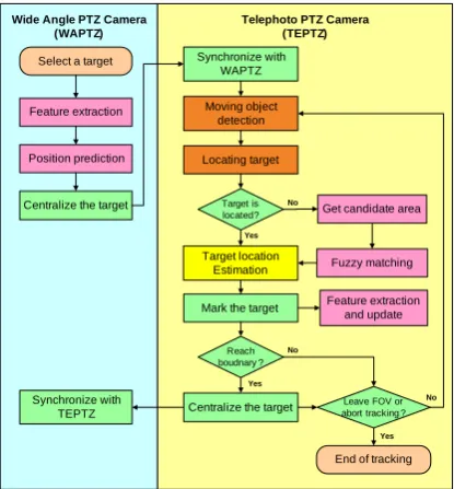
According to the above typical operation scenario, the operation process of the Eagle-Eye system is depicted in Figure 4, which is modified from our previous result [17]. The process on the left-hand side and right-hand side represents the operation of wide-angle PTZ camera (WAPTZ) and telephoto PTZ ca-mera (TEPTZ), separately. The process is performed iteratively and described as follows.
1. Initial phase: Before the surveillant selects a target for tracking, the operation of TEPTZ is synchro-nized with WAPTZ.
2. Target selection phase: When a target is selected on the real-time image of WAPTZ, its feature is generated from the corresponding object image for the fuzzy matching in the later phase. Besides, before TEPTZ is controlled to aim at the target’s current position, the target may leave the FOV of TEPTZ since it is moving during the camera’s rotation. Therefore, the target position is predicted based on the moving vector of the target. The system continues to the next phase after the feature and the predicted position is generated success-fully.
3. TEPTZ tracking phase: When the WAPTZ camera is controlled to centralize the target, the TEPTZ
camera is also synchronized to aim the area near the target. Two techniques are used in this phase for tracking the target. One is the moving object detection technique. The other is the fuzzy mat-ching technique. Moving object detection can be used to locate the target most of the time. If this technique fails, e.g., due to the occlusion or merging of objects, the fuzzy matching technique is used to locate the target. Two techniques are presented in detail later. Besides, the high zoom setting of TEPTZ causes the target to easily leave its FOV. TEPTZ is controlled in order to centralize the target when it reaches the image boundary. WAPTZ is also synchronized with TEPTZ to monitor the area around the target. If the target leaves the FOV of TEPTZ or the surveillant selects a new target, the system aborts the tracking of the current target.
Telephoto PTZ Camera (TEPTZ) Wide Angle PTZ Camera
(WAPTZ)
Centralize the target
Target location Estimation Select a target Synchronize with
WAPTZ
Feature extraction Moving object detection
End of tracking Synchronize with
TEPTZ
Mark the target Locating target
Get candidate area
Fuzzy matching No
Yes
Target is located?
Feature extraction and update Position prediction
No
Yes
Reach boudnary ?
Leave FOV or abort tracking ?
Centralize the target
No
Yes
Figure 4. The operation process of the Eagle-Eye system
The moving object detection and fuzzy matching techniques used in the above TEPTZ tracking phase are presented as follows.
3.3. Moving object detection
Background subtraction is a common technique for moving object detection. However, because of the rotation of PTZ cameras, the background model is difficult to establish. Therefore, a frame-based tempo-ral differencing technique is used instead. The steps are listed below:
1. Difference: Two successive frames are differenced to remove the common background.
2. Grey scale: The above result is converted to grey scale image.
4. Median filtering: The binarized image is smoothed with a median filter to remove noisy components. 5. Blob extraction: Blob (Binary Large Object) is
extracted from the above result.
6. Blob fusion: The nearest blobs are linked together into a single blob object.
An example of the above steps is shown in Figure 5. Two successive frames are shown in Figure 5(a) and (b). Then, the grey scale, binarization, median fil-tering, blob extraction and fusion are shown in Figure 5(c) to (h), separately. Such a technique enables the system to detect the moving object efficiently.
(a) (b) (c) (d)
(e) (f) (g) (h)
Figure 5. An example of the frame-based temporal differencing technique: (a) frame 1 (b) frame 2
(c) difference of frames 1 and 2 (d) grey scale (e) binarization (f) median filtering (g) blob extraction
(h) blob fusion
3.4. Feature extraction and fuzzy matching
When the target is occluded or merged with other objects, its size will change significantly according to the results of the moving object detection. Then, a fuzzy matching technique is used to locate the most likely position of the target image in the image con-taining the target, i.e., the candidate image. This tech-nique is modified from a fuzzy correlation of the color-histogram method proposed by Zhai et al. [18]. Assume that the image of a target is determined by the contour of a selected moving object; a candidate image is the image containing the target image. This technique is used to extract the feature and find the most likely position of the target image in the can-didate image. The feature extraction and fuzzy matching is performed according to the following steps:
1. Acquire an image systematically with the same size as the target image from the candidate image. 2. Transform the target and the image acquired in the
above step into grey scale and generate a 16 level color histogram.
3. Sort the 16 levels of the two images and denote them as hl (l=1 to 16) and hl’ (l’=1 to 16). The 16 levels are the features of the corresponding image. 4. Compute the similarity of the two levels when l
equals to l’ based on the following membership function.
(
)
(
(
)
)
' ' '
, max
, min ,
l l
l l l
l S
h h
h h h
h =
μ (1)
5. α2-cut defuzzification: μS
(
hl,hl')
is set to one when it is larger than α2; otherwise, it is set to zero. That is, this step is used to determine whether(
l, l')
S h h
μ is included in the similarity computa-tion. The value of α2-cut is set to 0.8 from the empirical results.
6. Similarity computation: the similarity Rh is computed according to Eq. (2). Hl represents the weight of the level l. Hl is set to one for uniform weight.
(
)
(
')
' 1
' ,
, min
where , , 2
l l l l
l l S M
l l
l h
h h H
h h H R
β
μ α
=
=
∑
= (2)
7. Find the acquired image with the maximum Rh. Its location is deemed as the location of the target image.
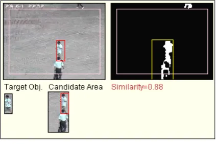
An example of the fuzzy matching technique is shown in Figure 6. The image of the target is captured before it merges with another object. When the merge occurs, the result of the moving object detection is shown on the right-hand side. The size of the image containing the target is changed significantly as mar-ked by a yellow rectangle. It is also the candidate image. After the above fuzzy matching steps are per-formed, the most likely position of the target is marked by a red rectangle. Its similarity (0.88) is the maximum of all the possible positions. The fuzzy matching technique is performed until they are split.
Figure 6. A fuzzy matching example
Besides, when the target object moves toward or away from the camera, its size is continuously chan-ged. Therefore, the image of the target object is captu-red and updated periodically for ensuring the accuracy of the fuzzy matching technique.
4. Prototype
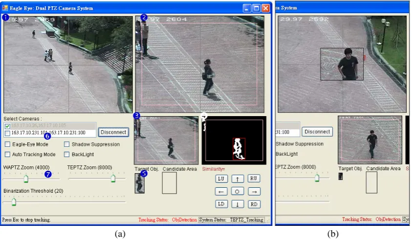
images labeled p and q are the results of fuzzy matching and moving object detection techniques, respectively. The images labeled r are the target ob-ject and candidate area used in the fuzzy matching technique. Those checkboxes labeled s are the opera-tion modes for different situaopera-tions. The “Eagle-Eye Mode” can merge the real-time images of WAPTZ and TEPTZ and becomes an eagle-eye view as shown in Figure 7(b). The “Shadow Suppression” checkbox is used to remove the shadow of a moving object. The shadow causes the change of the target image. The fuzzy matching step may fail since it is based on the histogram of the image. The “Auto Tracking Mode” is used under a very small number of moving objects. Once an object appears in the image of WAPTZ, the object is deemed as the target and the system
automa-tically starts the operation process. The “BackLight” checkbox is used to activate the backlight compensa-tion of the cameras for tracking objects during night-time. The track bars labeled t can be used to adjust the zoom values of cameras and the binarization thre-shold of moving object detection.
The prototype was implemented using Visual Stu-dio 2005. The camera is an AXIS 214 PTZ network camera with 18×optical zoom. The system can be in-stalled easily and operated almost instantly with simple setting. The moving object detection and fuzzy matching techniques are utilized alternatively to finish tracking the target. The surveillant can also enable the Eagle-Eye mode to simplify the view of two real-time images.
(a) (b)
Figure 7. Eagle-Eye prototype (a) the screen shot (b) the Eagle-Eye mode
5. Experimental studies
In this section, three experiments were designed to evaluate the tracking performance of the Eagle-Eye system. The performance is measured by the tracking success rate. The success or failure of a tracking task depends on whether the target is kept within the FOV of TEPTZ camera until the target leaves the open area. These three experiments are used to measure the tracking success rate under different situations, including daytime and nighttime, special moving paths, and different sites. They are presented as follows.
1. Tracking success rate during daytime and nighttime
In this experiment, the Eagle-Eye system is in-stalled to track objects in an open area at the campus, called “Red-Brick Square”. There are 200 moving objects chosen randomly as targets for tracking during daytime and nighttime, separately. That is, a total of 400 tracking tasks are performed in this experiment.
The backlight compensation function is enabled du-ring nighttime for the correct operation of Eagle-Eye system. The demonstration is depicted in Figure 8.
Figure 8. The demonstration of Eagle-Eye system during nighttime by enabling the backlight compensation function n
t r
p o
s
Besides, the average moving speeds of all the tar-gets are measured in pixels per second. The correspon-ding moving speed in kilometers per hour is also computed; it is used to analyze the tracking perfor-mance under various moving speeds. The experimen-tal results are listed in Table 2. The average success
rates are 91 and 79.5 percent for daytime and night-time, respectively. The success rate of low speed is usually higher than that of high speed as expected. The results show that the Eagle-Eye system can achieve a good tracking performance under different periods and moving speeds.
Table 2. The tracking success rate vs. moving speed and periods
Daytime Nighttime
Periods
Speed (pixels/sec ≅ km/hr)
Tracking counts
Success counts
Success rate (%)
Tracking counts
Success counts
Success rate (%)
3 – 5 ≅ 2-3.7 10 10 100 15 14 93.3
6 – 10 ≅ 4.5-7.5 58 54 93.1 80 63 78.8
11 – 15 ≅ 8-11 65 59 90.8 57 47 82.5
16 – 20 ≅ 12-15 54 47 87 45 33 73.3
>20 ≅ >15 13 12 92.3 3 2 66.7
Total Average
200 182 91
200 159 79.5
Table 3. The tracking success rate with merge condition
Daytime Nighttime
Periods
Speed (pixels/sec)
Merge counts
Success
counts Success rate (%)
Merge counts
Success counts
Success rate (%)
3 – 5 2 2 100 4 4 100
6 – 10 29 25 86.2 15 10 66.7
11 – 15 25 24 96 12 10 83.3
16 – 20 17 12 70.6 4 2 50
>20 6 5 83.3 0 0 0
Total Average
79 68 86.1
35 26 74.3
Besides, the merging or occlusion of the target with other objects may influence the tracking success rate. All of the tracking tasks with merge condition are measured separately and the results are listed in Table 3. The merge counts for daytime and nighttime are 79 and 35, respectively. The number of moving objects is usually small during the nighttime. It causes the merge counts to be small, too. The tracking success rates are 86.1 and 74.3 percent for daytime and nighttime, sepa-rately. It shows that the Eagle-Eye system can still achieve a good success rate under merge condition.
2. Tracking success rate with special moving paths
In the previous experiment, most trajectories of selected moving persons are stable and close to linear. In order to understand the limitation of the Eagle-Eye system, four special moving paths are designed to measure the tracking success rate. These paths are depicted in Figure 9. The success or failure of a tra-cking task depends on whether the system can keep the target within the FOV of TEPTZ while the target is moving along the specific path. The tracking is per-formed 20 times for every moving path. The results are listed in Table 4. The average tracking success rate is 83.8 percent. The success rate of the “circle” path is
the lowest, only 70 percent, because the moving di-rection of the target is constantly changing. The sys-tem may falsely predict the target’s position. The rotation of cameras relies on the predicted position and causes the failure of partly tracked targets. The success rates of the other three paths are close to that of the daytime, i.e., 91 percent. They show that the Eagle-Eye system still offers good tracking perfor-mance under these special moving paths.
3. Tracking success rate at another site
system can be installed quickly and operate effectively at another site.
Table 4. The tracking success rate vs. special moving paths
Moving Paths
Tracking counts
Success counts
Success rate (%) Rectangle 20 17 85 Triangle 20 18 90
Circle 20 14 70
Infinite 20 18 90
Total Average
80 67 83.8
Circle Infinite
(a) (b)
Rectangle Triangle
(c) (d)
Figure 9. Four different moving paths (a) circle (b) infinite (c) rectangle (d) triangle
Table 5. The tracking success rate of Eagle-Eye system installed at another site
Speed (pixels/sec)
Tracking counts
Success counts
Success rate (%)
Merge counts
Success counts
Success rate (%)
3 – 5 1 1 100 0 0 0
6 – 10 41 36 87.8 11 9 81.8
11 – 15 36 32 88.9 7 5 71.4
16 – 20 18 17 94.4 2 2 100
>20 4 3 75 0 0 0
Total/Average 100 89 89 20 16 80
Figure 10. The operation of Eagle-Eye system at another site
According to the above experimental results, the following points can be summarized:
(1) The Eagle-Eye system can provide a good tracking capability during daytime or nighttime and under special moving paths.
(2) The system can operate at any place quickly without special setting and keep good tracking performance.
(3) The system is feasible for monitoring a large open area. It enables the surveillant to obtain the view of
an eagle-eye. The system is also easy to operate for tracking any suspicious target in the area.
(4) The cooperation of two PTZ cameras to imitate an Eagle-Eye is novel and is also fulfilled in the implemented prototype.
Besides, the cost of a PTZ camera with high op-tical zoom is getting cheaper. The development of the Eagle-Eye system is consistent with this trend. The system can not only be operated independently, but also integrated with current digital surveillance system when necessary.
6. Conclusion and Future Works
target while continuing to monitor objects in the area around the target. According to the experimental re-sults, the Eagle-Eye system is feasible and achieves good tracking performance under various conditions.
There are several directions to be explored in the future. First, the implemented prototype communi-cates with the PTZ cameras via HTTP protocol. The response is not very efficient. Therefore, if the Eagle-Eye system can be integrated into the embedded sys-tem of the PTZ camera, it will help to simplify the system’s installation and improve the tracking success rate.
Second, when the open area is very large, one Eagle-Eye system is insufficient to monitor the whole area. Therefore, the cooperation of multiple Eagle-Eye systems is worth developing in the future. The main concern is the design of a uniform user interface without being influenced by the number of Eagle-Eye systems. The target tracking task can be performed seamlessly across multiple Eagle-Eye systems.
Third, the system provides a view from an eagle eye. The view could be displayed in the head-mounted display (HMD). A head rotation tracking technique can be used for controlling the Eagle-Eye system. For example, J. Lee proposed a human-computer interac-tion mechanism by utilizing a Wii Remote controller (Wiimote) [20]. Since Wiimote can track the source of infrared light, a surveillant may wear a glass with infrared transmitter to select the target or control the PTZ camera by rotating his head.
The above directions can increase the feasibility of the Eye system. More systems similar to Eagle-Eye system will be developed further to extend the application area of active cameras.
References
[1] E. Paliulis, R. Zemblys, G. Daunys. Image analysis problems in AOI systems. Information Technology
and Control, 2008, Vol. 37, No. 3, 220-226.
[2] D. Krstinić, D. Stipaničev, T. Jakovčević.
Histo-gram-based smoke segmentation in forest fire detec-tion system. Information Technology and Control, 2009, Vol. 38, No. 3, 237-244.
[3] R. Bodor, R. Morlok, N. Papanikolopoulos.
Dual-camera system for multi-level activity recognition.
Proceedings of 2004 IEEE/RSJ International
Confe-rence on Intelligent Robots and Systems (IROS 2004),
28 Sep.-2 Oct., 2004, Vol. 1, 643- 648.
[4] L. Marchesotti, L. Marcenaro, C. Regazzoni. Dual
camera system for face detection in unconstrained environments. Proceedings of 2003 International
Con-ference on Image Processing (ICIP 2003), 14-17 Sep.,
2003, Vol. 1, 681-684.
[5] C. Micheloni, E. Salvador, F. Bigaran, G.L. Foresti. An integrated surveillance system for outdoor security.
Proceedings of IEEE Conference on Advanced Video
and Signal Based Surveillance, 15-16 Sept., 2005,
480-485.
[6] H.C. Liao, Y.C. Cho. A new calibration method and
its application for the cooperation of wide-angle and pan-tilt-zoom cameras. Information Technology Jour-nal, 2008, Vol. 7, No. 8, 1096-1105.
[7] Bald eagle: Journey North Bald Eagles. 1997,
http://www.learner.org/jnorth/eagle/.
[8] S. Khan, O. Javed, Z. Rasheed, M. Shah. Human
tracking in multiple cameras. Proceedings of Eighth IEEE International Conference on Computer Vision
(ICCV 2001), 2001, Vol. 1, 331-336.
[9] Z. Tao, M. Aggarwal, R. Kumar, H. Sawhney.
Real-time wide area multi-camera stereo tracking.
Proceedings of IEEE Computer Society Conference on
Computer Vision and Pattern Recognition, 20-25
June, 2005, Vol. 1, 976-983.
[10] C. Micheloni, G. L. Foresti, L. Snidaro. A network of co-operative cameras for visual surveillance. IEE
Proceedings of Vision, Image and Signal Processing,
8 April, 2005, Vol. 152, 205-212.
[11] R. Yi, D. Xu, G. Junbin, M. Antolovich. Novel
me-thods for high-resolution facial image capture using calibrated PTZ and static cameras. Proceedings of IEEE International Conference on Multimedia and Expo, 23 June, 2008, 45-48.
[12] I.H. Chen, S.J. Wang. An efficient approach for the calibration of multiple PTZ cameras. IEEE
Transac-tions on Automation Science and Engineering, 2007,
Vol. 4, Issue 2, 286-293.
[13] P. Azzari, L. Di Stefano, A. Bevilacqua. An effective real-time mosaicing algorithm apt to detect motion through background subtraction using a PTZ camera.
Proceedings of IEEE Conference on Advanced Video
and Signal Based Surveillance, 15-16 Sept. 2005,
511-516.
[14] A. Bevilacqua, P. Azzari. High-quality real time
motion detection using PTZ cameras. Proceedings of IEEE International Conference on Video and Signal
Based Surveillance (AVSS ‘06), Nov. 2006, 23-28.
[15] N. Lu, J. Wang, Q.H. Wu, L. Yang. An improved
motion detection method for real-time surveillance.
IAENG International Journal of Computer Science,
2008, Vol. 35, Issue 1.
[16] I. Everts, N. Sebe, G. Jones. Cooperative object
tracking with multiple PTZ cameras. Proceedings of
the 14th International Conference on Image Analysis
and Processing, 10-14 Sept., 2007, 323-330.
[17] H.C. Liao, W.Y. Chen. A dual-PTZ-camera system
for visual tracking of a moving target in an open area.
The 11th International Conference on Advanced
Com-munication Technology (ICACT 2009), Phoenix Park,
Korea, Feb. 15-18, 2009, 440-443.
[18] H. Zhai, P. Chavel, Y. Wang, S. Zhang, Y. Liang.
Weighted fuzzy correlation for similarity measure of color-histograms. Optics Communications, 2005, Vol. 247, Issue 1-3, 49-55.
[19] AForge. Net framework.
http://code.google.com/p/aforge/.
[20] J.C. Lee. Human Computer Interface Research.
http://johnnylee.net/.
![Figure 2 [7]. Therefore, the design of the system mainly imitates the structure of an eagle’s eye](https://thumb-us.123doks.com/thumbv2/123dok_us/8767100.1754994/2.595.58.277.454.544/figure-design-mainly-imitates-structure-eagle-s-eye.webp)