Research Journal
Volume 11, Issue 2, June 2017, pages 146–158
DOI: 10.12913/22998624/70763 Research Article
DYNAMIC BEHAVIOR OF STEEL FRAMES WITH TUNED MASS DAMPERS
Kourosh Talebi Jouneghani1, Mahmood Hosseini2,
Mohammad Sadegh Rohanimanesh3, Morteza Raissi Dehkordi4
1 Department of civil engineering, Islamic Azad University Central Tehran Branch (IAUCTB), Tehran, Iran, e-mail:
2 International Institute of Earthquake Engineering and Seismology (IIEES), P.O. Box 19395-3913, Tehran, Iran,
e-mail: [email protected]
3 Department of civil engineering, Faculty of Technology and Engineering, Central Tehran Branch, Islamic Azad
University, Tehran, Iran, e-mail: [email protected]
4 School of Civil Engineering, Iran University of Science and Technology, P.O. Box 16765-163, Narmak, Tehran,
1684613114, Iran, e-mail: [email protected]
ABSTRACT
In this paper, the application of tuned mass damper in improving the response of
struc-tures is considered. At first, three frames of 3, 9 and 20 stories are evaluated in which time history analysis is done according to El – Straw earthquake. The maximum reduc
-tion of among the three men-tioned frames belongs to a 20-stories structure in which the rate of story displacement reduction is between 25 to 45%, and this indicates that
by increasing the height of the structure, the performance of tuned mass damper
im-proved. In the second part, the effect of semi-active tuned mass damper is studied on a 10-stories frame. Studies showed that using a tuned mass damper system with viscous damper with controller force decreases the average of maximum displacement of roof story down to 39.9 % and this amount of reduction is 22.8% for semi-active tuned
mass damper. Finally, the performance of tuned Single and multiple mass Damper is
evaluated on a 20-stories frame, and the results show that single and multiple dampers
decrease structures ‘responses and the performance of tuned multiple dampers depends
on the mass and frequency ratio and also concluded that the performance of tuned mul -tiple mass dampers is reduced by transition to middle of the structure stories.
Keywords: Earthquake, Tuned Mass Dampers, Vibration control, Dynamic behavior,
steel frames, Structural control.
INTRODUCTION
Structural control strategies are commonly used to some structures to protect them from undesired vibrations resulting from natural
haz-ards such as earthquakes and strong winds. Al -though the main types of structural control are active and passive systems, usage of the passive system is more common due to economic and physical conditions [11].
Out of a variety of passive control devices,
tuned mass dampers (TMDs) are widely used in
tall buildings. A TMD is comprised of mass con -nected to the structure by a spring and a dashpot
in parallel [7, 10].
Tuned mass dampers are installed in high rise buildings for damping vibrations. Ex
-amples include Citigroup Center in New York City, Yokohama Landmark Tower in Yoko
-hama, Burj Al Arab in Dubai, Trump World Tower in New York City, Taipei 101 in Taipei, a pendulum type TMD implemented to Taipei 101 building in Taipei, Taiwan in order to re
-duce vibrations [20].
If tuned correctly, a TMD could efficiently
reduce the response of a single linear degree
of freedom (SDOF) system. Hence, TMDs are used effectively to vibration control where the
structure remains linear, and a single mode
dominates the structural response [2, 8]. Under
seismic events, on the other hand, buildings are
designed to yield. Hence, detuning may take
place and appreciably reduce the efficiency of
the TMD. Moreover, several modes may sig -nificantly contribute to a seismic response. As
a consequence, the use of a single TMD may
reduce the overall seismic response, and the
use of TMDs for seismic mitigation has been avoided [19, 4].
The parameters of TM,; the frequency and
the damping ratio must be set properly for the
best gain. For this reason, Den Hartog devel
-oped closed form equations of optimum pa -rameters for different undamped degrees of
freedom (SDOF) of original system [9]. These expressions are for harmonic loading excita
-tions. In addition to that, Warburton and Ayor -inde proved that the time for obtaining
opti-mum TMD parameters for complex systems, the problem may be thought as an equivalent SDOF system if its natural frequencies are well separated [28]. Thompson obtained opti
-mum damper parameters with a locus method [24]. Warburton derived simple expressions for optimum harmonic and white noise random excitations [29]. Villaverde et al. proposed that TMDs implemented successfully when the modal damping ratios of the first two modes were equal [26÷27]. Sadek et al. extended the study of Villaverde [27] because Villaverde’s formulation does not cause equal damping in the first two modes of vibration, especially for large mass ratios [23]. Kareem considered the dynamics of base isolated buildings with pas -sive mass dampers and compared different
lay-outs of dampers [13].
A TMD was designed with numerical optimi -zation by Rana and Soong for control of a single
structural condition. Also they investigated the possibility of controlling multiple structural
con-ditions using multi-tuned mass dampers (MTMD) [21]. Also, optimum parameters of MTMDs were checked in several studies [16÷30].
Carotti and Turci designed an inertial tuned
damper using phasers in the Argand–Gauss
plane [5]. Chang derived optimum TMD design closed formulas for both wind and earthquake types of loading [6]. Lin et al. by TMD applied an extended random decrement way to reduce dynamic responses of buildings. Unlike previ -ous studies, they investigated displacement and
acceleration response spectra for structures with and without TMD [17].
An optimum semi-active tuned mass
damp-er with a magneto - rheological (MR) dampdamp-er was designed by Aldemir to reduce peak re -sponses of an SDOF structure subjected to a
broad class of seismic inputs [1]. Lee et al.
developed a numerical optimization algorithm
for buildings with TMD for decreasing per
-formance index value [15]. By the numerical searching technique, Bakre and Jangid ob
-tained explicit mathematic expressions for optimum parameters of TMD [3]. Rüdinger
investigated the effect of tuned mass dampers
with nonlinear viscous damping elements [22]. Hoang et al. researched optimum parameters
of tuned mass dampers for the seismic retrofit
of long-span truss bridges [12]. Marano et al. also optimized the TMD mass ratio which was
a preselected parameter in previous studies
about optimization of TMD [18].
Hence in this study, the performance of Tuned Mass Dampers (TMD) in reducing the nonlinear response of buildings under earthquake vibration
is investigated.
TDM AND CLOSED FORM EXPRESSIONS
The equations of motion of a multiple degrees of freedom (MDOF) linear system subjected to external loading P (t) are written as:
(1) Where M, C, K are mass, damping and stiffness matrices respectively. X (t) is the vector of the hori
-zontal displacements with respect to the ground. The M, C, K and x (t) for N degrees of freedom system is given in Equation. (2) – (5).
(6) In Eq. (6), the mode–shape matrix Ø serves to transform the generalized coordinates Y (t) to the geometric coordinates x (t).
With this change and permute plying by the
transpose of the i-th mode–shape vector ØT
i,
cou-pled dynamic equations can be write:
(7)
Because of the orthogonally conditions, all
components expect the i-th mode term in the mass, damping and stiffness expressions of Eq. (7) van
-ish. In this case above Equation can be write: (8)
Or alternatively:
(9) In which Mi, Ci, Ki, Pi (t) and Yi (t) are gen
-eralized mass, damping, stiffness, load, and dis -placement of the i-th mode, respectively.
Also, ωiand ξi are natural frequency and damp
-ing ratio of the i-th normal mode, respectively. Ex
-ternal loading P (t) is given by Eq. (10) for harmon
-ic loading and in Eq. (11) for earthquake excitation. In Equation (10) and (11), p0 is the amplitude, ͞͞ω is circular frequency of harmonic loading,ẍg(t) is the
ground acceleration and {1} represents a column
of ones. When the circular frequency of the applied load equals the natural frequency of the structure,
the generalized displacement of the corresponding
normal mode becomes unsteady. This situation is
called resonance.
(10)
(11)
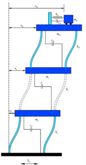
Fig. 1. System model of multi-storey building
struc-ture with single TMD
(3)
(4)
(5) Mi, ci, ki, and Xi are mass, damping coeffi
-cient, stiffness and horizontal displacement of i-th storey of the building (i = 1, 2. . . N). Md, cd
and kd are mass, damping coefficient, the stiffness of TMD which is implemented on the top of the building as seen in Fig. 1. Xd is the displacement
STUDYING DYNAMIC BEHAVIOR OF
TWO-DIMENSIONAL FRAME
In this part, the effect of using tuned mass
damper in improving the response of structures
is considered. Therefore, three frames of 3, 9 and 20 stories are evaluated. At first dynamic
analysis of time history is applied to obtain the dynamic response of the studied structures and
then it is influenced by El – Straw earthquake.
For studying tuned mass damper characteristic on the dynamic response of the structure, the
dampers parameters with different character -istics are added to the mathematical model of structure and time history analyses have been
repeated for structures. The obtained results are compared, and tuned mass damper effect is char
-acterized by the first mode in the reduction of
structure response.
The characteristics of Mass and stiffness of studying frames are assumed as rigidness of floor
and non–rotation.
Structure A – short building (3 stories)
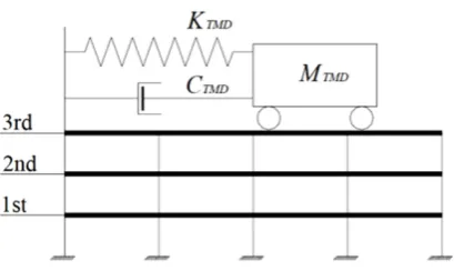
The modeled structure was in 3 stories, and its height was 11.89 meters. The details of the structure are according to Figure 2, and the sto
-ries characteristics are shown in Table 1. The percent of supposing damper for first and second mode is 3%.
Structure B – Average-Height Building (9 stories)
The second modeled structure is in 9 stories and its height is 37.19 meters. The details of struc
-ture are according to Figure 3 and the stories char
-acteristics are shown in Table 2. The percent of suppose damper for first and second mode is 2%.
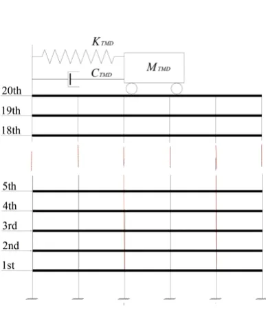
Structure C – Tall Building (20 stories)
The third structure is in 20 stories and its height is 88.70 meters. The details of structure are
according to Figure 4 and the stories
characteris-tics are shown in Table 3. The percent of suppose dampen for first and second mode is 1%.
To study the performance of tuned mass
dampers in the conducted analyses and to
evalu-ate the effect of different parameters of the ap -plied damper, parameters of damper are changed
and the results are presented. These parameters
Fig. 2. Physical model of Structure A
Table 1. Stories characteristics of Structure A
Story stiffness (N/m) Mass (Kg) Story
218637631.3 4.79E+05 1
218637631.3 4.79E+05 2
218637631.3 5.20E+05 3
Fig. 3. Physical model of Structure B
Table 2. Stories characteristics of Structure B
Story stiffness (N/m) Mass (Kg) Story
2.48+08 5.05E+05 1
5.78E+08 4.95E+05 2
5.78E+08 4.95E+05 3
4.37E+08 4.95E+05 4
4.37E+08 4.95E+05 5
3.09E+08 4.95E+05 6
3.09E+08 4.95E+05 7
3.09E+08 4.95E+05 8
Table 3. Stories characteristics of Structure C
Story stiffness (N/m) Mass (Kg) Story Story stiffness (N/m) Mass (Kg) Story
603996113.6 2.76E+05 11 430820723 2.82E+05 1
603996113.6 2.76E+05 12 1147963450 2.76E+05 2
603996113.6 2.76E+05 13 1147963450 2.76E+05 3
387753452.8 2.76E+05 14 1147963450 2.76E+05 4
387753452.8 2.76E+05 15 737959948.4 2.76E+05 5
387753452.8 2.76E+05 16 737959948.4 2.76E+05 6
341399184.7 2.76E+05 17 737959948.4 2.76E+05 7
341399184.7 2.76E+05 18 737959948.4 2.76E+05 8
22864247.5 2.76E+05 19 737959948.4 2.76E+05 9
22864247.5 2.925E+05 20 737959948.4 2.76E+05 10
Table 4. TMD parameters for different cases
KTMD ζTMD MTMD Cases
Adjusted According to first mode
2
0.5 % of total stories mass
1
5 2
10 3
Adjusted According to first mode
2
1 % of total stories mass
4
5 5
10 6
Adjusted According to first mode
2
2 % of total stories mass
7
5 8
10 9
Fig. 4. Physical model of Structure C
Fig. 5. Time history of El - Centro earthquake
scaled acceleration in time history analysis is
presented in Figure 5.
The maximum computed displacement re
-sponse and parameter J for used mass dampers have been presented in Tables 5 and six respectively.
SEISMIC VIBRATION CONTROL OF A
TEN-STORY BRACED FRAME WITH THE USE
OF SEMI-ACTIVE TUNED MASS SYSTEM
In this part, the behavior of a 10-story X- braced steel frame structure with semi-active tuned mass damper is evaluated. The structure are presented in Table 4. Due to a high contribu
-tion of the first mode in structure response, all dampers are adjusted to the first mode.
The stimulation of the applied base in the
structure modeling is time history of El -
Cen-tro earthquake acceleration that its maximum
floor is considered as a rigid diaphragm and frame
behavior is assumed as shear one. One degree of
freedom is considered for each frame story which
is the J horizontally movement. In these types,
structure mass can be concentrated in the center
of the floor. With assumption of linear behavior of structure, stiffness and mass matrixes are ex
-tracted according to the definitions of these two. Values of the mass and stiffness matrix of sto
-ries are given in Table 7. After determining mass and stiffness matrix of structure, one can deter
-Table 5. Maximum response and percent reduction of maximum response displacement of structures
Structure C Structure B Structure A
Percent reduction of
maximum response displacement
Maximum response displacement
(m)
Percent reduction of
maximum response displacement
Maximum response displacement
(m)
Percent reduction of
maximum response displacement
Maximum response displacement
(m)
- 0.3291 - 0.1909 - 0.1053 without damper
30.8721 0.2275 18.8057 0.1550 2.1842 0.1030 Damper 1
28.1373 0.2365 19.9581 0.1528 2.1842 0.1030 Damper 2
24.9164 0.2471 21.2677 0.1503 2.0893 0.1031 Damper 3
41.4464 0.1967 13.3054 0.1655 4.4634 0.1006 Damper 4
40.2309 0.1927 15.2960 0.1655 4.3685 0.1007 Damper 5
38.8028 0.2014 17.4437 0.1576 4.1785 0.1009 Damper 6
31.0240 0.2270 7.9099 0.1758 8.5470 0.0963 Damper 7
38.0431 0.2039 10.4767 0.1709 8.5470 0.0963 Damper 8
44.9711 0.1811 13.3054 0.1655 8.1671 0.0967 Damper 9
Table 6. Parameter J of structures
Structure C Structure B Structure A
J J J
1.0 1.0 1.0 without damper
0.9243 0.9083 0.9627 Damper 1
0.9281 0.8862 0.9630 Damper 2
0.9328 0.8631 0.9637 Damper 3
0.9088 0.9342 92.54 Damper 4
0.8792 0.9009 0.9264 Damper 5
0.8871 0.8669 0.9281 Damper 6
0.9218 0.9847 0.8524 Damper 7
0.8196 0.9466 0.8546 Damper 8
0.8200 0.9033 0.8586 Damper 9
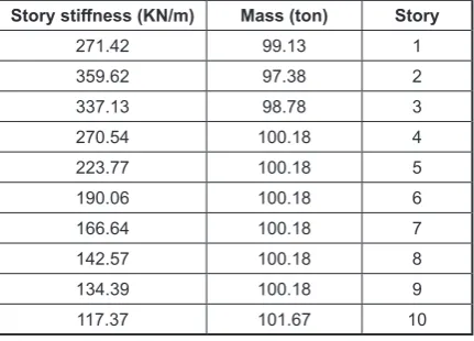
Table 7. Mass and Stories stiffness of the considered
structure
Story stiffness (KN/m) Mass (ton) Story
271.42 99.13 1
359.62 97.38 2
337.13 98.78 3
270.54 100.18 4
223.77 100.18 5
190.06 100.18 6
166.64 100.18 7
142.57 100.18 8
134.39 100.18 9
117.37 101.67 10
Table 8. Natural frequencies of the structure
Natural frequency
(rad/sec) Mode
Natural frequency
(rad/sec) Mode
63.32 6 7.43 1
70.80 7 19.53 2
79.29 8 31.71 3
90.91 9 43.26 4
Parameter β in Table 9 and Fig. 6 is an op
-timum ratio. As seen in Figure 6, the maximum
structure response reduction happens for a
speci-fied β. In Table 9, optimal values of this coeffi
-cient are expressed along with reduction percent
-age of displacement for the maximum roof story 1-R for 4 applying earthquakes for damping of 10% and the mass ratio of m0 = 0.05. To deter -mine βopt, weighted averaging is used, based on that its value is 0.94.
In this study, accelerograms related to the
Chi-Chi - Taiwan (1999), Bam - Iran (2003), Kocaeli - Turkey (1999) and Northridge - Cali
-Table 9. Optimum βcoefficient for considered earthquakes
Northridge Kocaeli Chi-Chi Bam Station
0.91 1.18 0.84 0.89 β
23.5 39.0 49.1 47.8 Reduction of Displacement(1-R)%
mine natural frequency of different modes of the structure; the values of a natural frequency of 10 modes of structure are given in Table 8.
The maximum ratio of displacement at the roof story in an uncontrolled mode to Controlled one is considered as a criterion in studying the
TMD system performance, and trial-error method is used to determine optimal values of TMD sys -tem parameters.
According to Figure 6, the maximum reduc
-tion was shown in response to an optimal mass
ratio, for this reason, m0 = 0.05 in which m0 is
TMD mass ratio to structure mass.
Fig. 6. The influence of parameters β and m0 in the reduction of structure Response
Table 10. Average Displacement and Average Acceleration of stories without TMD according to the considered earthquakes
Average Acceleration
(cm/s2) Average Displacement (cm) Story Average Acceleration (cm/s2) Average Displacement (cm) Story
866.1 10.86 6 292.0 2.056 1
898.8 12.85 7 473.1 3.560 2
932.5 14.84 8 639.0 5.085 3
1015 16.36 9 792.1 6.835 4
1249 17.31 10 862.7 8.781 5
Table 11. Average Displacement and Average Acceleration of stories with TMD controller according to the earthquakes
Reduction (%)
Average Acceleration
(cm/s2)
Reduction (%)
Average Displacement
(cm) Story
Reduction (%)
Average Acceleration
(cm/s2)
Reduction (%)
Average Displacement
(cm) Story
20.0 693.7 21.8 8.496 6 14.1 250.9 20.0 1.644 1
22.9 693.0 21.5 10.09 7 16.1 396.7 20.5 2.831 2
25.4 695.1 21.8 11.61 8 19.6 513.4 21.0 4.019 3
23.3 778.0 21.0 12.93 9 19.9 634.6 21.4 5.372 4
fornia (1994) earthquakes are used. Structure motion equation without controller and Struc
-ture motion equation with inactive tuned mass system are solved by MATLAB software, and the average maximum of displacement and sto
-ries acceleration were determined influenced by four earthquakes, These values are
present-ed in Tables 10 and 11 without the controller and with TMD controller. The results show the average maximum of structure responses with
inactive tuned mass system reduces according
to the earthquakes effects.
To compare the effect of Semi-active tuned
mass damper in reducing structure responses,
Table 12. Specification of Semi-Active Fluid Viscous Damper
Maximum Damping Force (KN) Damping coefficient (KN.sec/mm) Weight (Kg)
Minimum Maximum
1000 1 200 1300
Fig. 7. The effect of parameter K on the average reduction of maximum response of structure with STMD controller according to the considered earthquakes
Mass and stiffness of the damper are equal to the
obtained optimal values for inactive tuned mass damper, so, to provide controller damping, a
vis-cous damper was built in the system. The charac
-teristics of this damper is shown in Table 12. To determine structure responses with
semi-active tuned mass damper, control force is
com-puted by LQR method. in LQR algorithm, K should be determined first. According to Fig
-ure 7, for Ks greater than 15, struct-ure response
is increased, so the average values of reducing
maximum displacement and the accelerate of the
roof having semi-active tuned mass system,
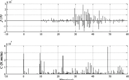
com-pared to the one without controlling system, is decreased more influenced by earthquake and the value of viscous damper force does not exceed its maximum capacity according to Figure 8.
To determine structure response having
semi-active tuned mass damper the space form
of equation state of structure motion is solved in MATLAB software and structure responses are obtained according to Table 13. The obtained re
-sults show that semi-active tuned mass system with LQR controller can cause average reduction of max displacement of stories compared to the
structure having inactive tuned mass damper and
without control. Therefore, according to Figure 9 its ability in average reduction of the maximum acceleration of upper stories of structure is lower
than compared to the inactive one.
EVALUATING SEISMIC PERFORMANCE
OF TUNED SINGLE AND MULTIPLE MASS
DAMPER ON TALL STRUCTURES
In this part, tuned multiple mass damper
per-formance is considered on tall structures. At first,
mass dampers are selected regarding structure
and time history analysis under Northridge, Loma prieta and Tabs earthquakes are done using MAT
-LAB simulation software, and performance indi
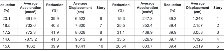
-Table 13. Average Displacement and Average Acceleration of stories with STMD controller according to the considered earthquakes
Reduction (%)
Average Acceleration
(cm/s2)
Reduction (%)
Average Displacement
(cm) Story
Reduction (%)
Average Acceleration
(cm/s2)
Reduction (%)
Average Displacement
(cm) Story
20.1 691.9 39.9 6.523 6 15.3 247.3 39.3 1.248 1
18.5 732.6 40.8 7.600 7 25.5 352.4 39.4 2.157 2
17.2 772.3 41.9 8.628 8 31.1 439.9 39.9 3.058 3
14.0 7873.2 41.3 9.613 9 33.5 526.9 39.7 4.126 4
15.0 1062 39.9 10.41 10 26.54 633.7 39.4 5.319 5
Fig. 9. Comparison of Average Displacement and
ces of tuned single and multiple ones are com-puted and compared.
Tuned multiple mass damper system has 2 concentrated mass dampers which was designed as two states. In the first state, the first mass damper is designed with a mass ratio of 0.03 and 0.02 based on the first mode and the second mass damper is designed with a mass ratio of 0.01 and 0.02 based on the second mode. In the second state, the first and second mass dampers are de
-signed based on first with the mass ratio of 0.03, 0.01 and 0.02, 0.02.
8 out of 12 performance indicators are pro
-posed by Yang which is shown with a J1-J12 sign.
Six measuring indices of the first performance of mean square root of responses are out of selected stories of structure and stimulus. 6 next indices are the maximum responses of selected stories of structure and stimulus. Eight indices of J1-J4 and
J7-J10 are used out of these 12 indices.
The considered structure is 20 stories, and its
structural characteristics, such as the mass of each
story is 200·103 kg and its stiffness is 600·103
kN/m. Damping matrix has been computed using rail equation and for 2% damping ratio. The first natural frequency of the structure is 4.19 radians per second; the second one is 12.56 radians per second, the effective mass of the first mode is 3320·103 kgand that of the second one is 366·103
kg. Time history analysis is done in MATLAB software under the earthquake whose accelerate grams are shown in Table 14.
The ratio of tuned single mass damper is con
-sidered 0.04 and the parameters of mass damper are shown in Table 15.Structure and tuned mass damper equations are built in a separate block in MATLAB and damper are placed as a force in a point of structure which should be effective.
J is an Operation index according to Yang suggestions. J1 to J6 are the root mean square of
Table 14. Specification of considered earthquakes
Earthquake Mag. Station Name Source Distance (Km) Comp. PGA (g)
Loma Prieta (1989) 7.1 Corralitos – Eureka Canyon Road 7 0o 0.630
Loma Prieta (1989) 7.1 Capitola- Fire Station 9 0o 0.472
Northridge (1994) 6.7 Arleta Nordhoff Ave- Fire Station 9.9 90o 0.344
Tabas (1978) 7.4 Kashmar 199.1 L1 0.34
Table 15. The parameters of Tuned Single and Multiple Mass damper
Structure μ β Φ f ξ ω MTMD(Kg∙f) KTMD(KN/m) CTMD
STMD – Mode 1 0.04 2 % 1 0.957 0.215 4.19 132800 2135256.23 239599.6
MTMD – Mode 1 0.03 2 % 1 0.967 0.19 4.19 99600 1635085 158583.1
MTMD – Mode 2 0.09 2 % 1 0.912 0.307 12.5 32200 4356192.3 256033.1
MTMD – Mode 2 0.18 2 % 1 0.848 0.386 12.5 66400 7527170 643835.6
MTMD – Mode 1 0.01 2 % 1 0.988 0.113 4.19 33200 568957.75 31439
MTMD – Mode 1 0.02 2 % 1 0.977 0.159 4.19 66400 1114085.5 88806.55
Time history analysis of a 20-stories structure is equipped with single and multiple dampers under Northridge earthquake according to figure 10.
response at chosen story and J7 to J10 are the maxi -mum response of story in the studied structure.
Time history analysis of a 20-stories struc
-ture is equipped with single and multiple damp
-ers under Northridge earthquake according to Figure 10.
As are seen in Figure 10, tuned single and
multiple mass dampers have reduced displace-ment response, and roof story accelerate of structure effectively, multiple mass damper reduces displacement response more than the single one.
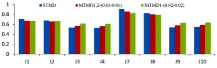
According to Figure 11, tuned multiple
mass dampers which have been designed based
on the first mode, have better performance in reducing displacement responses under
North-ridge earthquake; tuned multiple mass dampers which have been designed based on the first and
the second modes, have better performance in
reducing acceleration responses; while accord
-ing to Figures 12 and 13, tuned s-ingle mass
dampers have better performance in reducing
displacement responses under Loma prieta earthquake and tuned multiple mass dampers which have been designed based on the first
and the second modes have better performance
in reducing acceleration responses;tuned sin -gle mass dampers have better performance in
reducing responses under Tabas earthquake (Figure 14) and tuned multiple mass dampers just have better performance in reducing maxi -mum acceleration response.
In continues, tuned multiple mass dampers
are designed based on the first mode, the first
damper is placed on the roof and the second one
are in 10 and 15 stories. As seen in Figures 15
and 16, tuned multiple mass dampers perfor-mance is reduced by the transition to middle sto-ries. Its reason is story acceleration, proportion
with mass dampers; in a 20-storey structure, the
Fig. 11. Different Performance of Tuned Single and Multiple Mass Damper of 20-storey structure accord
-ing to the Northridge earthquakes
Fig. 12. Different Performance of Tuned Single and Multiple Mass Damper of 20-storey structure accord
-ing to the Loma-Capitola earthquakes
Fig. 13. Different Performance of Tuned Single and Multiple Mass Damper of 20-storey structure accord
-ing to the Loma-Corralitos earthquakes
Fig. 14. Different Performance of Tuned Single and Multiple Mass Damper of 20-storey structure accord
-ing to the Tabas earthquakes
Fig. 15. Comparison of the performance of Multiple Tuned Mass Damper of middle stories of structure
according to the Northridge earthquakes (mass ratio: 0.01-0.03)
Fig. 16. Comparison of the performance of Multiple Tuned Mass Damper of middle stories of structure
roof story has the most acceleration and mass
damper shows the best performance in roof.
CONCLUSION
In this research, the dynamic behavior of steel
structures was considered by applying tuned mass damper in structures with different height and characteristics. At the first stage, three two-dimen
-sional frames of 3, 9 and 20 stories were studied,
in this study, all states are regulated with the first mode frequency, and structure analysis was done by El-Centro time history analysis. The results of displacements response show that these types of
dampers have had an optimal performance in
im-proving structure behavior. The maximum value
of displacement reduction in the upper story of
3-stories structure is between 3-9%, in 9-stories structure is between 8-21% and in 20-stories structure is between 25-45%. The studies showed
that tuned mass damper performance is increased by increasing structure height and increasing the mass of mass damper improves its performance, but increasing damping of related viscous damper does not improve the mass damper performance necessarily.
In the second study, semi-active tuned mass
damper was used for reducing the vibrations of 10-stories structure. Studies show that using a tuned mass damper system along with a viscous damper with controlling force cause that the av
-erage maximum of roof displacement is reduced 39.9% and the average maximum of roof acceler
-ation is reduced 15%. While using inactive tuned
mass system, the average roof displacement is
reduced 19.5% and average maximum of roof ac
-celeration is reduced 22.8%. Comparing semi-ac
-tive tuned mass system to inac-tive one shows that
semi-active one has had more impressive perfor-mance in reducing the average displacement of
structure stories and the maximum acceleration of
1st-6th stories of structure, so inactive tuned mass
system have better performance in reducing the
average maximum acceleration of 7th-10th stories.
In the last part of this article, the Seismic performance of single and multiple regulated
mass dampers were considered in a 20-stories structure; the obtained results show that displace -ment and acceleration responses are reduced
us-ing tuned sus-ingle and multiple mass dampers. The structure is studied under different earthquakes,
and the tuned multiple mass dampers had the best
performance in reducing displacement responses
of the structure under Northridge earthquake. Tuned mass dampers which have been designed based on the first and the second modes under Loma prieta earthquake, have better performance in reducing acceleration responses. Tuned single mass damper has better performance under Tabas earthquake, and just tuned multiple mass dampers have shown better performance in reducing maxi -mum acceleration response.
REFERENCES
1. Aldemir U. Optimal control of structures with semi-active-tuned mass dampers. J Sound Vib 2003, 266, 847–74.
2. Bachmann H, Weber B. Tuned vibration absorbers for ‘‘lively’’ structures. Structure Engineering Int, 5(1), 1995, 31–6.
3. Bakre S.V., Jangid R.S. Optimal parameters of
tuned mass damper for damped main system.
Structure Control Health Monit2007 ,14 ,448–70
4. Caetano E, Cunha A, Magalhes F, Moutinho C.
Studies for controlling human induced vibration of the Pedro e Inês footbridge, Portugal. Part 1, as-sessment of dynamic behavior. Engineering
Struc-ture, 32(4), 2010, 1069–81.
5. Carotti A, Turci E. A tuning criterion for the inertial
tuned damper. Design using phasors in the Argand–
Gauss plane. Appl Math Model 1999, 23, 199–217.
6. Chang C. C. Mass dampers and their optimal de -signs for building vibration control. Engineering
Structure 1999, 21, 454–63.
7. Chang C. C. Mass dampers and their optimal de -signs for building vibration control. Engineering
Structure, 21(5), 1999, 454–63.
8. Dallard P, Fitzpatrick AJ, Flint A, Le Bourva S, Low A, Ridsdill Smith RM, et al. The London mil
-lennium footbridge. Structure Engineering, 79(22), 2001, 17–21.
9. Den Hartog J. P. Mechanical vibrations. 3rd Ed. New York, McGraw-Hill, 1947.
10. Feltrin G, Weber F, Gsell D. On the relative motion of tuned mass dampers. In, 3rd European confer
-ence on structural control, 2004, 12–5.
11. Fujino Y, Abe M. Design formulas for tuned mass dampers based on a perturbation technique. Earth
-quake Engineering Structure Dynamic, 22(10), 1993, 54-833.
12. Hoang N, Fujino Y, Warnitchai P. Optimum tuned
13. Kareem A. Modelling of base-isolated buildings with passive dampers under winds. J Wind Engi
-neering Ind Aerodyn 1997, 72, 323–33.
14. Lee C-L, Chen Y-T, Chung L-L, Wang Y-P. Opti -mal design theories and applications of tuned mass
dampers. Engineering Structure, 2006, 28, 43–53. 15. Lee CL, Chen YT, Chung L-L, Wang Y-P. Opti
-mal design theories and applications of tuned mass
dampers. Engineering Structure, 2006, 28, 43–53.
16. Li C, Qu W. Optimum properties of multiple
tuned mass dampers for reduction of translational and torsional response of structures subject to
ground acceleration. Engineering Structure2006, 28, 472–94.
17. Lin C. C, Wang JF, Ueng JM. Vibration Control iden
-tification of seismically excitedm.d.o.f structure-PT
-MD systems. J Sound Vib 2001, 240, 87–115. 18. Marano G. C., Greco R, Chiaia B. A comparison be
-tween different optimization criteria for tuned mass dampers design. J Sound Vib 2010, 329, 4880–90. 19. Meinhardt C., Dressen O., Dalmer F. Increase of
the structural damping dueto the application of
tuned mass dampers TMD subject to the footbridge construction. In, Footbridge conference, 2008. 20. Rana R., Soong T. T. Parametric study and simpli
-fied design of tuned mass dampers. Engineering Structure, 20(3), 1998, 193–204.
21. Rana R., Soong T. T. Parametric study and simpli
-fied design of tuned mass dampers. Engineering Structure 1998, 20, 193–204.
22. Ründinger F. Tuned mass damper with nonlinear
viscous damping. J Sound Vib 2007, 300, 932–48. 23. Sadek F, Mohraz B, Taylor A. W, Chung R. M. A
method of estimating the parameters of tuned mass
dampers for seismic applications. Earthquake En
-gineering Structure Dynamic1997 ,26 ,617–35 24. Thompson A. G. Optimum damping and tuning
of a dynamic vibration absorber applied to a force
excited and damped primary system. J Sound Vib 1981, 77, 403–15.
25. Villaverde R., Koyama L. A. Damped resonant ap -pendages to increase inherent damping in buildings
.Earthquake Engineering Structure Dynamic 1993, 22, 491–507.
26. Villaverde R., Martin S. C. Passive seismic control of cable-stayed bridges with damped resonant ap
-pendages. Earthquake Engineering Structure Dy
-namic 1995, 24, 233–46.
27. Villaverde R. Reduction in seismic response with heavily-damped vibration absorbers. Earthquake Engineering Structure Dynamic 1985, 13, 33–42. 28. Warburton G. B., Ayorinde E.O. Optimum ab
-sorber parameters for simple systems. Earthquake Engineering Structure Dynamic 1980, 8, 197–217. 29. Warburton G. B. Optimum absorber parameters
for various combinations of response and excita
-tion parameters. Earthquake Engineering Structure Dynamic 1982, 10, 381–401.
30. Yau J-D, Yang Y-B. A wideband MTMD system
for reducing the dynamic response of continuous truss bridges to moving train loads. Engineering