Tailoring SOFC electrode microstructures for improved performance
P.A. Connora*, X. Yuea, C.D. Savaniua, R. Pricea, G. Triantafylloua, M. Cassidya, G. Kerherveb, D.J.
Payneb, R. C. Maherc, L. F. Cohenc, R.I. Tomovd, B.A. Glowackid,e, R.V. Kumard, J.T.S. Irvinea* a. University of St Andrews, School of Chemistry St Andrews KY16 9ST, Fife, UK
b. Department of Materials, Imperial College London, London, SW7 2AZ, United Kingdom
c. The Blackett Laboratory, Imperial College London, Prince Consort Road, London, SW7 2BZ, United Kingdom
d. Department of Materials Science and Metallurgy, University of Cambridge, 27 Charles Babbage Road, Cambridge, CB3 0FS, UK
e. Institute of Power Engineering ul. Mory 8, 01-330 Warsaw, Poland
Abstract
The key technical challenges that fuel cell developers need to address are performance, durability and cost. All three need to be achieved in parallel; however, there is often competitive tensions meaning that e.g. performance is achieved at the expense of durability. Stability and resistance to degradation under prolonged operation are key parameters There is considerable interest in developing new cathodes better able to function at lower temperature to facilitate low cost manufacture. For anodes, the ability of the SOFC to better utilise commonly available fuels at high efficiency avoiding coking, resistance to sulfur in bio-derived fuels and oxidation resistance at high utilisation are all key parameters. Optimising a new electrode material requires considerable processing development. The use of solution techniques to impregnate an already optimised electrode skeleton, offers a fast and efficient way to evaluate new electrode materials. It can also offer low cost routes to manufacture novel structures and to fine tune already known structures. Here we discuss infiltration and impregnation methodologies, look at spectral and surface
characterisation and review the extensive recent efforts to optimise both cathode and anode functionalities. Finally we review recent exemplifications and look to future challenges and opportunities for the impregnation approach in SOFCs.
1.
Introduction
The optimisation of solid oxide fuel cell (SOFC) electrode microstructures for improved performance has been a continual goal in the development of these devices. The critical areas of any fuel cell electrode microstructure are the triple phase boundaries (TPB). This is where electrons, ions and reactants meet and electrochemical reactions occur. Whilst this zone is extended with mixed ion conductors, the three phase boundary zone is still the focus of electrochemical activity. Thus, for good electrochemical performance, the TPB must have sufficient length and catalytic activity to allow electrochemical exchange to take place and move species across the boundaries. The stability of both the TPB and the catalysis to both time dependant ageing and changes in gas composition is vital in producing a robust, high performance and durable SOFC. These four features must be present in all good electrodes: porosity (gas “conduction”), ionic conduction, electronic conduction and sufficient catalytic activity. Some components may contribute to more than one feature. Additionally, the electrode must be stable under all the conditions it is likely to undergo in a fuel cell environment.
for the oxidation of the fuel (hydrogen gas in the simplest case). The porosity allows for the transport of the fuel into the electrochemical interfaces and triple phase boundaries. The close intermixing of these three phases gives an extended and diffuse interface over which the
electrochemical reactions can take place and results in a very efficient electrode, which to date has proved very difficult to replace even though it has several significant technical issues such as degradation on redox cycling of the NiO to Ni and back,1,2 carbon deposition from hydrocarbon
based fuels3 and sulphur poisoning.4 There are of course engineering based solutions around these
problems such as use of safe gases to prevent reoxidation in case of fuel gas loss, having steam in the system to promote reforming rather than cracking reactions, anode modification to reduce the propensity to coking/poisoning or the presence of a desulphurisation system upstream of the anode. However, most desirable is a fuel cell design that is tolerant to these problems making the whole system more robust.
The cathode is where the oxygen reduction reactions occur. A commonly used cathode composition is a composite mixture of YSZ and strontium doped lanthanum manganite perovskite (La1-xSrxMnO3)
(LSM). Here the LSM provides the electronic conduction and catalytic functions and the YSZ the structural component and ionic conduction, with the porosity forming the triple phase boundary. 5
To further improve performance more recent cathodes have utilised mixed conductors such as strontium doped lanthanum cobaltite (La1-xSrxCoO3) (LSC) or strontium doped lanthanum cobalt
ferrite (La1-xSrxCo1-yFeyO3) (LSCF), where the mixed conduction nature of the material has greatly
increased electrochemical exchange 6,7, not least by expanding the TPB by increasing the ionic
conduction further over the surface.However, this increased performance comes at a cost because these materials systems have some issues with increased coefficient of thermal expansion, thermal stability and higher reactivity, with the most widely used doped zirconia electrolytes (especially during processing) leading to degradation and detrimental interfacial phase formation. 8,9 Although
modifications to both composition and process protocols have reduced the impacts, it does constrain the system and reduces the options for optimisation.
The drive to lower operating temperatures for fuel cells to lower the materials cost of manufacture puts higher demands on the catalytic materials, requiring newer, more active materials, which often do not have the chemical and thermal stability as the bulk materials used for the electronic and ionic conductivity. This makes them difficult to add to a bulk process for cell fabrication. By separating the processing of the bulk, stable ceramic components from that of the catalytic components it becomes possible to tailor the processing of each and to optimise them for their specific requirements.
A particularly useful method for achieving this is impregnation, also known as infiltration, where a porous, skeletal ceramic support (a scaffold) is created which is then infiltrated with a liquid phase containing the desired component. The scaffold can be processed using traditional bulk ceramic methods to optimise porosity and mechanical attributes whereas the infiltrate can be dried and fired under a different, less harsh set of conditions, to result in tailored microstructures. This has the advantage of only placing the small amounts catalyst on the surface, where it can be active and not in the bulk where it is of less use. Because of this, impregnated electrodes often show higher power density and lower resistance compared to electrodes fabricated using traditional techniques. 10, 11,12
Clearly impregnation of electrodes is a low cost route to fabrication and, if applied successfully to give suitable nanostructured interfaces, enhanced performance will be delivered. Thus the real underlying challenges are to combine performance with durability and then to advance the technique to large scale manufacture.
1.1 Methodologies
There are three basic methods for impregnation:
(A) Impregnation with metal-salt solutions with various additives (urea, citric acid, glycine, ethylene glycol, etc.).
(B) Impregnation with nanoparticles in suspension. (C) Molten salt impregnation.
The use of metal salts (A) is the simplest and most common method also having the greatest flexibility in the choice of solvent and additives. In most cases, metal nitrates are used, dissolved in water or alcohols. The use of a surfactant is beneficial for facilitating the penetration of solution inside the porous structure by reducing the surface tension. It does however require multiple infiltration cycles in order to achieve high loading levels and there can be a non-uniform distribution of the infiltrate depending on how the initial solution and the resultant compound wet the surface. The use of nanoparticles (B) allows the synthesis of the catalyst phase in advance, but the inks are difficult to stabilise and may clog the pores leading to gas diffusion obstruction. The use of molten salts (C) facilitates uniform high loaded infiltration but is more complicated and so less common in electrochemical applications.
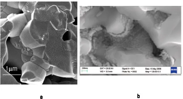
Figure 1 Examples of microstructures evolved from impregnation a) An electron conducting backbone (green) is infiltrated with precursor (orange) which forms dispersed catalyst particles across the surface. This can be a single material or multiple phases. b) An Ionic conducting backbone (yellow) is coated with precursors, which will form a continuous electron or mixed ion electron conducting perovskite phase (orange). In some cases surface morphology may change with atmosphere to increase triple phase boundary. c) An Ionic conducting backbone (yellow) is coated with precursors, which will form a percolating network of electronic conducting particles. [Modified from Ref.13]
This brings up a number of interesting questions with respect to wetting, the interaction of surfaces and surface energies at various points in the infiltration process. Firstly, one would expect the surface energy of the precursor solution to be instrumental in both how the solution penetrates the porous scaffold and also how it then deposits onto this surface. This will of course vary with each set of solution and scaffold materials. Secondly, even after the heat treatment to form the initial
catalyst phase the wetting and interaction of the scaffold and catalyst surfaces continue to play a central role in the stability and durability of the electrode. Therefore, a deeper understanding of how the various phases present in an electrode interact is vital to improve design and optimisation of these systems.
The interactions of the impregnated catalyst particles with the scaffold surface and the gas species controls the catalytic behaviour observed. With the presence of nano-sized particles this may not have the same behaviour as given by the bulk materials and so observations of the electrodes while operating is also needed, to optimise the amount and type of impregnated species. This needs observation at long distance by spectroscopic techniques such as XPS or Raman, which can observe the evolution of electrodes under realistic conditions of elevated temperature, and air or reducing gases.
An early example of work on infiltration was focussed on overcoming the limitations of nickel coking in hydrocarbon fuels. One potential catalyst of interest was copper, which showed very low
propensity to promote coking. However the low melting point of both copper and copper oxide, which was below the temperatures required for the bulk ceramic processing routes prevented the use of a bulk Cu/YSZ cermet. By infiltrating a porous YSZ scaffold with a copper nitrate solution then decomposing this to the oxide, it was possible to produce a finely dispersed copper catalyst at temperatures well below the melting points of both the oxide and metal which offered the
opportunity for a high performance anode with good carbon tolerance. 14 However even though the
melting point issues could be avoided during processing, the metallic copper still proved too mobile at operational temperatures, leading to large scale agglomeration and so rapid deactivation of the anode. 15
This review will briefly touch on the wetting and observation of the impregnated electrodes before discussing various anode and cathode systems.
1.2
Wetting and impregnation
The interactions between a liquid and a solid or indeed a solid with another solid is determined by the surface energy of the materials and the interfacial energies of the systems so formed. This is usually expressed as a wetting process, with thin even coatings coming from positive surface
interactions the surface energies of the solid can be obtained. 16,17,18,19,20 Wetting behaviour of
various liquid-solid ceramic interactions have been studied in, for example, sodium batteries21, direct
carbon fuel cells22, and the use of ceramic-glass seals for SOFCs. 23,24,25,26 There is, however, little
work on the wetting properties for impregnation of SOFCs.
During the impregnation there are two sets of surface interactions, the first one being the solution in contact with the dense walls of the porous scaffold creating a solid-liquid interface. The ability for the solution to move through the porous substrate is highly dependent on the interfacial energy of the system, which again depends on the specific surface properties of the solution and the solid. 25
The other surface interaction is the solid-solid surface interactions during the thermal treatment for sintering the final impregnated materials where the surface energies control the size and shape of the final catalyst. Therefore to understand the processes forming the impregnated catalyst materials the surface properties of the support, the solution and the final material need to be known.
The reported studies on impregnation cover the wetting of the impregnate solution on the various substrates and how it penetrated into the porous scaffold. This was typically done by simple measurement of the contact angle of the impregnate solution on a polished dense surface of the scaffold material. This allows the tuning of the solvent (and additives)27 resulting in reasonable
infiltration. A number of surfactants have been used including Triton-X100 and X-4528, 29, 30, 31,
2-butoxyethanol 32, CTAB33 or Pluronic P123 (BASF Corp)34. Several studies by Lou et al. 28,35, 36, 37 have
shown that tuning the wetting properties of the infiltrate ink with organic solvents was another efficient way to improve the wettability on scaffold grains.
This however does not cover the solid-solid interaction of the final formation of the catalyst. This is very difficult to measure directly, and so the surface energy of the materials is measured separately leading to the calculation of the surface energy, and hence type of interaction. The methodology to study the interactions has been led by MetLab at the University of Patras. The extraction of the surface energy usually requires the application of a combination of experimental methods
multiphase equilibration technique16,17,18,19,20,38 or indentation technique 39. For this reason, most of
the literature data have been derived from theoretical evaluations40. The underlying physical
processes are well understood and can be described by a set of empirical and semi-empirical equations. 41,42 The surface energies of the liquid metals are known,43 as are the polar and the
dispersion forces contribution, the surface energy of all the polar liquids used 44,45,46 which can be
used to get the surface energies of Alumina18 43, zirconia19, Y
2O347, YSZ20 and Ceria38, over a range of
temperatures.
The power of these surface measurement can be observed in the mixed ionic electronic conductor yttrium and titanium doped zirconias/Ni metal system48,49 where the Ti content of the ceramic
changed both the measured contact angle, and hence surface energy, and the electrode
performance. This allowed the ceramic to be optimised for the best interaction with the Ni phase.
These fundamental measurements are required in order to understand the processes happening during impregnation, ultimately leading to practical control or design of materials. However, this work is still under-valued and needs significantly more research to establish a robust framework.
2.
Observation of infiltrated electrodes
develop an understanding of the microstructure-performance relationship.50 The use of in-situ or at
least in operando techniques such as Raman or XPS provides useful mechanistic information.
The various microscopy and spectroscopic methods that have been used to study conventional SOFC electrodes in situ or in operando are covered elsewhere.51 To obtain chemical information about
SOFC electrodes in operando, spectroscopic methods are needed to collect data from a distance due to the high temperature and need for gas environment. This limits methods to those based on photons such as: Emission IR52, Raman53, X-ray Diffraction (XRD)54, (Ambient pressure) X-ray
Photoelectron Spectroscopy ((AP)XPS)55,56, and the various x-ray absorption (XAS) methods (XANES,
EXAFS etc)55,57.
To study impregnated electrodes, the techniques also need to be both surface sensitive and give chemical information about the catalytically active surface species. IR gives information about the species adsorbed to the surface and not the surface itself, but is difficult perform at hot IR emitting electrodes. XRD principally gives information about the bulk of the majority phase, and so is less sensitive to the smaller volume impregnated phases. The various x-ray absorption methods need a high intensity source such as a synchrotron and so are less available and thus have not been greatly applied to infiltrated electrodes as yet. An exception to this is a recent study on infiltrated LSCF sintered porous powder cathodes using synchrotron ultra-small angle x-ray scattering (USAXS). This allowed the evolution and growth of nanoparticles of LSC and lanthanum zirconate particles to be followed through liquid phase impregnation and subsequent annealing.58 Clearly such X-ray
absorption methods are an important approach that will be widely applied in the future.
Probably the most available and informative methods are Raman and XPS. Raman is surface sensitive and gives observations on the metal oxide vibrations of both the scaffold and impregnate phase. It is also based on visible light, and so has less problems with the IR emission of the hot electrodes. XPS, or for in operando work Ambient Pressure XPS, gives both the elements present on the surface and their oxidation states, and how they change under fuel cell conditions. These two techniques are the ones most used for impregnated electrodes.
2.1
In-situ Raman
Raman spectroscopy59 is a chemically specific, non-invasive, optical characterisation technique
usually used in combination with a scanning modality that provides diffraction limited spatial information and mapping. It has been widely employed to provide insight regarding the processes that occur in SOFC materials during or after operation60. Raman is best described as a near-surface
characterisation technique because the optical penetration depth typically ranges between 10s of nanometers to a micron depending on the porosity, material composition, the oxidation state of the materials under study and the laser wavelength used. The combination of near surface sensitivity, chemical specificity and high spatial resolution means the technique is well suited to examining the impact of impregnation on the reaction kinetics within a SOFC environment.
Raman spectroscopic investigations of SOFCs can be broadly grouped into three subsets – ex-situ, in-situ and in-operando with ex-in-situ characterisation being the easiest to perform and in-operando, requiring specialised bespoke equipment61, the most difficult. Although not yet widely studied,
Raman spectroscopy can provide key information regarding the effectiveness of impregnation via any of these types of measurement. Over the last decade, in-situ and in-operando Raman
spectroscopy has been developed to investigate reaction kinetics62, reaction intermediates,
temperature distributions63, sulphur poisoning64,65,66, material oxidation states67 and SOFC operation
on carbon fuels68 under realistic operating conditions. Raman has been particularly successful in
deposition and redox interactions across the TPB69. Figure 2 shows an example of how Raman can be
used to investigate redox interactions in SOFC materials at the TPB. Figure 2 A shows a typical Raman spectrum obtained in-situ from a gadolinium doped ceria (cerium gadolinium oxide, CGO)-NiO cermet using a 514nm laser. The main peak at approximately 450cm-1 is the F
2G mode of Ceria
while the broader peak at approximately 1100 cm-1 is a combination of NiO overlapping with a
second order mode of the CGO. Both of these peaks are directly related to the oxidation states of the two materials and can be used to monitor their relative oxidation states in real time. Figure 2B shows the integrated intensity of the Ceria peak for both pure and composite CGO as a function of time while the sample is exposed to dry hydrogen. The CGO in the cermet is observed to reduce more quickly and to a greater extent than the pure CGO due to the hydrogen spillover across the TPB from Ni to CGO. This process is shown schematically in Figure 2 C. Finally the effect of the Ni is seen more clearly on the reduction of the same materials during reduction in humidified hydrogen as shown in Figure 2 D. These results are discussed in more detail in Maher et al,69 but clearly show
[image:7.595.89.520.300.558.2]how Raman could be used to study the effects of impregnation of SOFC anodes on their redox properties.
Figure 2 A: An example Raman spectrum of CGO-NiO cermet in-situ at 600°C. B: Example in-situ Raman monitoring of the reduction of CGO-NiO cermet and pure CGO in dry and wet (humidified to 3% H2O) hydrogen. CGO reduces faster and to a greater extent when combined with NiO. This is
due to the spillover of hydrogen from the Ni to the CGO at the TPB and the effect of the hydrogen spillover over the TPB is even larger in the wet gas.. C: Schematic illustration of the hydrogen spillover process. . Adapted from Advanced Science, 2016 3 (1), 1500146 63 (CC BY 4.0)
Raman has been found to provide particularly rich information regarding carbon deposition on SOFC anodes, in particular Raman peak ratios reveal details of the crystallinity (graphitic vs amorphous), and the relative amount of carbon present as well as their location 63,70. Understanding the specifics
composition and catalyst enhancement (adding small amounts of precious metals for example) has also been characterised extensively 77,78,79. Patterned electrodes combined with high resolution in-situ mapping has allowed TPBs to be precisely controlled and carbon deposition characterised as a function of distance from it80. Such measurements help to improve our understanding of how
changes in the TPB affect carbon deposition and could be extended to study other critical processes. As a result, they are directly relevant to understanding the effects of impregnation of anodes given the close control of the TPB impregnation techniques allow.
2.2
X-ray photoelectron spectroscopy (XPS)
X-ray photoelectron spectroscopy (XPS) is (principally) an ultra-high vacuum (UHV) surface characterisation technique used in the investigation of the chemistry and physics of materials81. It
provides quantitative information about the elemental composition and chemical environment (e.g. oxidation state) of the surface and can be a useful technique to examine the active redox couples, such as the oxygen storage/release property of the ceria-based solid solution and the chemical states of the dopant and the host ions. The reversible CeO2 – Ce2O3 reduction transition associated
with oxygen-vacancy formation and migration is directly coupled with the process of localization/delocalization of the 4f electron of cerium82. Traditionally, a significant drawback of the
technique is the inability to study samples in anything other than under UHV conditions (i.e. 10-9
mbar or lower). As a result, most of the studies found in the literature on solid oxide fuel cell were investigated using standard XPS. An important point to note is that the principal core level of cerium, the 3d, has a very complex line shape. An example of a fitted spectrum of the Ce 3d core level is shown in Figure 3 for CeO2 infiltrated on porous YSZ. The complexity of the Ce 3d, has been fully
described by Kotani et al.83, where it originates from the close proximity of the 4f level of the CeO 2 to
the O 2p valence band with which it hybridises. This requires careful peak fitting of the resulting spectra, and depending on the composition can require up to 10 peaks being required for an accurate and representative fit. For stoichiometric CeO2, the Ce4+ chemical environment gives rise to
six peaks, observed at the (on average) binding energy positions of 882 eV (v), 888.7 eV (v’’), 898.2 eV (v’’’), 900.7 eV (u), 907.3 eV (u’’) and 916.4 eV (u’’’). The designations (u’,v’…etc) denote the range of final states available from the photoemission process. Non-stoichiometric CeO2-x, with the
Ce3+ present in the material, gives rise to a further four peaks, found at (average) binding energy
position of 880.4 eV (v0), 884.2 eV (v’), 898.3 eV (u0) and 902.5 eV (u’). In total there are up to ten
Figure 3. Ce 3d XPS spectra from the CeO2 infiltrated on porous YSZ (dots), fit (solid blue line), Shirley-type background (dashed line), and components assign to Ce4+ (light blue) and Ce3+ (light red).
Henderson et al.84 used XPS, as well as temperature programmed desorption (TPD), to investigate
the surface chemistry of water on the oxidized and reduced surfaces of a thin film of CeO2 (111) on
YSZ (111). They quantified the level of reduction using the Ce3d3/24f0 photoemission peak at 917 eV
(u’’’) resulting from Ce4+ sites. By comparing with literature studies of reduction of single crystal
CeO2 (111), they found that the volume-to-surface ratio of ceria samples influences partly the
reduction conditions, and finding detectable levels of surface Ce3+ sites. Hegde et al.85 undertook a
structural investigation using XPS, XRD and H2-TPR, of transition metal, noble metal, and rare-earth
(R.E.) ion substituted ceria and found a relationship between the oxygen storage capacity (OSC) and structural changes induced by the dopant ion in CeO2. They found that transition and noble metal
ion substitution in ceria greatly enhances the reducibility of Ce1-xMxO2-δ (M= Mn, Fe, Co, Ni, Cu, Pd,
Pt, Ru), whereas R.E. ion substituted Ce1-xAxO2-δ (A = La, Y) has little effect in improving the OSC.
Jiang et al. 86 investigated infiltrated Pd nanoparticles catalyst on Ni/GDC as these particles are the
most widely studied catalysts for the O2 reduction and in particular the hydrocarbon oxidation
reactions. Using XPS they found the existence of the Pd/PdOx redox couple during the H2 oxidation
reaction which are most likely the cause for the enhanced adsorption and diffusion processes of the H2 oxidation reaction on the surface of the Ni/GDC anode.
Recently, there has been significant improvement of the electrostatic lens system of the hemispherical analyser using in photoelectron spectroscopy, allowing surfaces to be investigated by XPS whilst at pressures of several mbar of a gas. With a growing number of investigations using ambient pressure X-ray photoelectron spectroscopy (APXPS) of operando SOFCs being carried out using this technique 87,88,89,90,91,92. Zhang et al.87 was the first (APXPS) study of an operating solid oxide
electrochemical cell. The device consisted of a CeO2-x/YSZ/Pt single-chamber cell and was studied
under 1 mbar of H2 and H2O gases at a temperature of 750 ˚C. The mixed ionic/electronic
APXPS measurements of local surface Ce oxidation states while applying electric potentials reveal the active ceria regions during H2 electro-oxidation and H2O electrolysis. This demonstrated that the
active electrochemical region extends approximately 150 µm away from the current collector and that significant shifts from the equilibrium surface Ce3+/Ce4+ concentrations were needed to drive
the electro-oxidation of H2 and the electrolysis of H2O. Nenning et al.90 also studied an operando
SOFC, this time of a LSC (La0.6Sr0.4CoO3) cathode and an STF (SrTi0.7Fe0.3O3) anode under high
temperature and pressure conditions. Their study revealed that in an oxidizing atmosphere all materials exhibit additional surface species of strontium and oxygen, and that cathodic polarization in reducing atmosphere leads to the reversible formation of a catalytically active Fe0 phase.
Gabaly et al.89 studied the different oxidation steps of a Ni electrode from Ni/YSZ/Pt SOFC using
operando APXPS. They found that there are three distinct steps in the oxidation of the Ni anode in a hydrogen environment. In the first two steps, the Ni exposed to the gas remains metallic, but the Ni at the interface between the anode and the electrolyte YSZ is oxidized. In a third step, they claim that the Ni oxidises in the form of NiOOH, a species not previously reported in the literature of these SOFC materials.
3.
Impregnated Anodes
There are a number of review papers available on infiltration of SOFC anodes, focused in large part on metal based cermet anodes and on some ceramic based anodes, including (La, Sr)(Cr, Mn)O3
(LSCM) and SrTiO3.10,93,94,95 Here we will review the very recent progress in the development of
impregnated SOFC anodes (or fuel electrodes in SOECs) since the last review paper in 2013, following the types of scaffold used. Some previous work will be included from a different perspective.
3.1 Electrolyte material based porous scaffold
Impregnation into YSZ based frameworks has been most widely studied, as it ensures the mechanical stability, good contact and matched thermal expansion between electrode and YSZ electrolyte. Many materials have been applied to a YSZ based anode via impregnation including M (Ni, Cu, Co)/ceria,10 ,96,97,98,99 LSCM,100,101,102,103 (La, Sr)(Sc, Mn)O
3104 etc. See also the previous reviews on
these materials. 10.93,94,95, Of the various catalysts being introduced into YSZ scaffold, (La,
Sr)(M,Mn)O3 (M= Ti, Cr) stands out with unique morphology on the surface of YSZ.100,102,103 Corre et
al.103 found that, after solution impregnation and high temperature sintering in air, the resulting
LSCM forms a thin smooth film on top of YSZ grains, which resembles a liquid wetting on a solid surface and is in great contrast with most of the other impregnates that often appear as discrete or aggregated particles, patches, or flakes on the scaffold after sintering. As shown in Figure 4, this smooth coating of LSCM breaks into interconnected nanoparticles upon reduction which offers extensive triple phase boundaries for the H2/CH4 oxidation reaction, as well as CO2 reduction
reaction. 102 The wetting of LSCM on YSZ is restored after switching back to oxidising atmosphere. It
Figure 4 Infiltrated LSCM microstructures showing morphology change in differing atmospheres a) from fairly continuous in oxidising (calcination in air at 1200˚C) to b) distinct nanoscale grains in reducing atmosphere (5 hours in humidified H2 (3% water). Reprinted with permission from Chemistry of Materials 2009, 21, 1077. Copyright 2009 ACS Publications.
Xia et al. 105 created a novel YSZ scaffold structure by phase-inversion tape casting method, and the
resulting microstructure featured channelled pores with graded pore size and porosity in gas delivery layer and electrochemical reaction layer. The double perovskite Sr2Fe1.5Mo0.5O6-δ (SFM) was
infiltrated into this graded porous YSZ scaffold, forming a highly continuous network giving electronic conduction on the surface of YSZ scaffold. Remarkable performance was demonstrated from this novel nanostructured SFM-YSZ fuel electrode in both fuel cell and electrolysis cell
operations (without safe gas which is usually necessary for Ni-YSZ cermet electrodes). At 800 ˚C with H2 (3% H2O), a peak power density of 1.08 W cm-2 was achieved in fuel cell mode, higher than that
from a Ni-YSZ electrode (0.8 W cm-2) under the same conditions; the current density values reached
1.1 A cm-2 and 1.46 A cm-2 at 1.5V in electrolysis mode with dry CO
2 and CO2-H2O respectively. The
infiltrated SFM-YSZ also exhibited good stability in a short-term test at 1.3V for CO2-H2O
co-electrolysis, indicated chemical stability between SFM and YSZ at below 1000 ˚C.
The main issue with using a YSZ framework is that due to its purely ionic conductive nature it poses problems for efficient electronic processes such as charge transfer and current collection. There needs to be a large amount of highly electronic conducting phase added to overcome these
problems, which in turn compromises the performance and durability of the impregnated anode due to the high tendency of nanoparticles to coarsen. Work continued with YSZ scaffold has been related to improving the thermal stability and poor electrochemical activity of Cu/Ceria based anodes.106,107
Dual metal infiltration has been found to be advantageous for retaining the uniform dispersion of metal-ceria network and mitigation of the aggregation of Cu particles, and thus optimised
morphology and reinforced electrochemical performance. Basu et al. incorporated Fe into the Cu-CeO2-YSZ anode matrix and used various techniques to investigate the structural, morphological and
electrochemical properties of dual metals /CeO2 based anode.106 With the presence of Cu, the
reduction of iron oxide was promoted; whilst at the same time, the presence of Fe improved the dispersion of Cu-ceria network, enabling a better electrical connectivity between Cu, Fe, and ceria catalyst particles, which reduced the sintering of Cu to some extent. These contributed to a higher maximum power output observed on the Cu-Fe-CeO2-YSZ anode for H2 and CH4 oxidation at 800 ˚C.
However, stability of such an anode (with 1wt% Pd to further enhance oxidation activity) was still a concern after a short-term operation (~46hrs) in CH4 fuel at 800 ˚C at 0.6 V. Performance decreased
carbon deposition. Poor carbon tolerance was also reported on Pd (0.5wt%) and Pd/CeO2
impregnated LSCM-YSZ composite anode for CH4 oxidation, while in contrast, high resistance to
coking was observed on Pt and Pt/CeO2 containing anode among Ni, Pd, Pt and Ceria catalysts.108
The interplay between multiple infiltrated phases was found of great importance in maintaining the metal catalyst small size, compared to only metal impregnation. Boaro et al. investigated the effect of redox treatments on the morphology and performance of SOFC anodes prepared via infiltration of Cu and Ce0.5Zr0.5O2 (CZ) into porous YSZ skeleton.107 The infiltrated CZ showed higher reducibility and
electronic conductivity under SOFC operating conditions above 800˚C, however, it was suggested that a structural change to a pyrochlore phase might happen in CZ, which would impose mechanical stress on the electrolyte/electrode interface and cause delamination. On the other hand, an in-situ redox cycle at 700˚C led to significant increases in the power density of a Cu-CZ/YSZ//YSZ//YSZ/LSM cell in 3% humidified H2-air, which was due to the rearrangement of the morphology and
microstructure of the CZ oxide at the electrode/electrolyte interface and to the redistribution of copper leading to improved Cu-CZ connectivity. This is clearly supported by the SEM shown in Figure 5. The interplay between Cu and CZ plays a fundamental role in determining the anode
[image:12.595.120.480.312.444.2]electrochemical activity.
Figure 5 SEM images of a porous YSZ infiltrated with 10wt% Cu and 20 wt% CZ, before (a) and after oxidation at 700 ˚C and subsequent reduction (b). Reprinted with permission from Journal of Power
Sources 2014, 270, 79. Copyright 2014 Elsevier.
Gadolinium doped Ceria ((Gd, Ce)O2, GDC) electrolyte material has also been used as a porous
skeleton with subsequent infiltration as SOFC anodes.109,110 Ni impregnation was conducted into a
GDC scaffold that was produced with a mixture of nano-scale (5 nm) and larger commercial (0.5 μm) powders.109 The addition of nano-sized particles allowed increased porosity and better sintering of
the GDC scaffold at reduced temperature as low as 1000˚C. Han et al. investigated the impregnation of Sr2Fe1.5Mo0.5O6-δ (SFM) into a porous GDC skeleton based on SOFC with GDC as electrolyte. The
ohmic resistance at 600˚C for a SFM-GDC electrode decreased from 0.82 Ω cm2 for a traditional
composite to 0.48 Ω cm2 when prepared via impregnation. The polarization resistance from the
impregnated anode was also significantly reduced. Furthermore, fairly good durability was observed on the impregnated anode fuelled by H2 with 100ppm H2S, indicating excellent sulfur tolerance from
the SFM impregnated GDC anode.
Treating the scaffold surface prior to impregnation can be used to tailor the electrode
microstructure and its electrode properties. De Guire et al. treated the NiO-GDC SOFC anode with some organic surfactants, including thiol (1-dodecanethiol, CH3C11H22SH) and sulfonate, before
depositing nanocrystalline ceria from aqueous solution, and studied the role of these organic surfactant pre-treatments on ceria microstructure and sulfur tolerance at various SOFC operating conditions.111 The functional groups introduced from the surfactant pre-treatment impacted on the
It was found in this study that a thicker and more uniform ceria coating was produced from the thiol pre-treatment than from the sulfonate pre-treatment. As a result, the direct or thiol treated
ceria/Ni-GDC anode provided the best sulfur tolerance with the idea that ceria nanoparticles may act to impede the sulfur adsorption on Ni which degrades cell performance significantly.
3.2 Perovskite based scaffolds
The use of ceramic anodes based on perovskite materials has been proposed for improved robustness.112 On reduction, in typical conditions present in the fuel electrode, these materials
exhibit reasonable electronic conduction and excellent redox stability, contributing to a good electrode performance. The lack of catalytic activity towards fuel oxidation can be compensated by impregnation of catalytically active materials. In a method which is similar to that described above, appropriate mixtures of nitrate precursor solutions can be infiltrated in the perovskite framework that was pre-fired at high temperature. Both of the most common perovskite anodes, (La
1-xSrx)(Mn0.5Cr0.5)O3 (LSCM) and (La1-xSrx)TiO3 (LST), have been successfully infiltrated in this way.9,12
3.2.1 Perovskite LSCM based scaffold
The perovskite LSCM has been considered as alternative anode material to replace Ni-cermet because of its mixed electronic and ionic conductivity, electrochemical activity for the oxidation of a range of fuels, including methane, and superior resistance to coking and sulfur poisoning.113,114
Nonetheless, the electrochemical properties of LSCM on its own are often not sufficient to facilitate the fast oxidation reactions needed at the anode, especially when it has been sintered at high temperature to make good contact with dense electrolyte. Its electronic conductivity is low in low pO2 atmospheres due to the p-type conductivity in LSCM. Therefore, it is essential to add both
catalytically active and highly conducting phases to improve its anode performance.115,116
Metal impregnations on porous LSCM anodes have been tested in SOFC operated for H2/CH4
oxidation and in SOEC for steam-carbon dioxide co-electrolysis.117,118 Different amount of Co on pure
LSCM anode were prepared and tested.117 The Co loading was vital to ensure good electronic
conduction and sufficient catalytic activity, with small amounts leading to scattered Co particles on the surface of LSCM, thus poor electronic conduction, and a very high loading forming a core-shell structure that contains dense Co particles on the surface of the LSCM core (Figure 6). The core-shell structure was found detrimental for efficient gas transportation to the active sites in LSCM based anode. Cu-infiltrated porous LSCM was used as the fuel electrode for steam-CO2 co-electrolysis cell,
with LSGM electrolyte and LSCF oxygen electrode.118 The introduction of Cu (20 wt%) improved the
electronic conductivity of the electrode effectively, thus significantly lowered ohmic resistance was observed. Despite much improved performance due to metal impregnation, the absence of an oxide ion conductor in metal modified LSCM anode may restricts the reaction active sites to the
electrode/electrolyte interface, originated from the fairly low ionic conductivity in LSCM in reducing atmosphere. To get around this problem, a LSCM/Sm0.2Ce0.8O2 (SDC) composite backbone was used
Figure 6 Model of LSCM backbone impregnated with: (a) 0 mg cm−2 Co, (b) 0.56 mg cm−2 Co, (c) 1.66 mg cm−2
Co, (d) 2.22 mg cm−2 Co, (e) 3.88 mg cm−2 Co. Reprinted with permission from International Journal of
Hydrogen Energy 2014, 39, 7980. Copyright 2014 Elsevier.
The impregnation of mixed electronic and ionic conducting material, such as doped ceria, is advantageous, offering both higher conductivity and good catalytic properties compared with a metal impregnation. The effect of Sm0.2Ce0.8O2 (SDC) impregnation on the electrochemical
performance of LSCM anode was investigated by Zhu et al in SOFC running with 5-10% H2/Ar.120 With
the aid of electrical conductive relaxation (ECR) measurements, it was observed that the surface exchange coefficient was improved by a factor of 28 at 850˚C, with the dispersion of nano-sized SDC particles on the surface of LSCM. This is ascribed to a much extended TPB compared to a bulk LSCM-SDC composite. The incorporation of LSCM-SDC into LSCM matrix also provided an extra oxide ion
conduction path besides faster surface reaction, which consequently enhanced anode activity towards H2 oxidation.
An LSCM based anode was reported to benefit significantly from infiltration of multiple components with diverse functionalities. With multiple infiltrations of GDC (50 wt%) and Pd (0.5 wt%) into LSCM scaffold, comparable performance with a well-engineered Ni-cermet in a high temperature CO2
electrolyser has been reported by Yue et al.121 High temperature was necessary to attach a pure
LSCM electrode to the dense YSZ electrolyte, thus interfacial contact is often a concern for LSCM based scaffold anode. A porous YSZ interlayer between the electrolyte and LSCM scaffold was found effective to improve contact between electrolyte and LSCM scaffold.
3.2.2 Perovskite LST based scaffold
Doped strontium titanates have been widely investigated as potential SOFC anode scaffolds, owing to their high conductivity, robustness in hydrocarbon fuels and good compatibility with YSZ
electrolyte.112,122,123 By doping at either A site or B site and by varying the stoichiometry, the
properties of these n-type, electronically conducting materials can be tuned to improve their electrochemical activity.124,125 However, the electro-catalytic properties of these materials tends to
be insufficient, so impregnation with active catalyst, such as doped ceria and/or Ni, is an effective strategy to boost the performance of strontium titanate anode.
When appropriately reduced lanthanum doped SrTiO3 (LST) shows good electronic conductivity,
which is promising as a conducting scaffold for impregnated anode systems. In particular the 10% A-site deficient La0.20Sr0.25Ca0.45TiO3 (LSCTA-) can exhibit a conductivity of 28-30 S cm-1 at 900 ˚C.126 The
addition of the calcium also improves the sinterability of the material, and by careful control of particle morphology, allows a well bonded grain structure to be obtained while maintaining adequate porosity for gas transport functions. One of the advantages of the conducting scaffold is that the catalyst phase can be kept to a minimum, usually less than 5 wt%, which minimises any risks of physical damage on redox cycling even if utilising Ni.
Irvine et al. have carried out extensive studies on infiltration into the A-site deficient La0.2Sr0.25Ca0.45TiO3 (LSCTA-) anode SOFC, testing with H2 as well as CH4.112,127,128,129,130 With
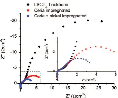
impregnated ceria (6-10 wt%) and Ni (3-5 wt%), a dramatic enhancement in anode performance was obtained compared to that of the bare LSCTA- backbone and the backbone with ceria only.127 As
shown in Figure 7, the performance enhancement mainly comes from a major decrease in the magnitude of the low frequency arc. When infiltrated with a mixture of Ni and CeO2, cells showed
the presence of Ni particles of 50-100 nm size, whereas the cell with only Ni decorated LSCTA- anode
showed performance that suffered from severe degradation due to sintering of the Ni particles. The tailoring of the electro-catalytic properties of LSCTA- anode by combined ceria and Ni infiltration was
also demonstrated in a thick anode supported structure fabricated by aqueous tape casting, where 6% ceria and 4% Ni were coated on a 450 μm thick porous LSCTA- anode (pre-reduced at 1000˚C. A
max power density of 960 mW cm-2 was obtained on testing in H
2 fuel at 800˚C.129 These used a
mixture of LSCTA- powders that were pre-fired at different temperatures to provide a matched
[image:15.595.81.278.195.359.2]thermal expansion in the scaffold with YSZ electrolyte.
Figure 7 Cell impedance from LSCTA- backbone with either 10 wt% CeO2 or with 10 wt% CeO2 + 5 wt%
Ni at 900 ˚C in H2 with 1% H2O at OCV. Reprinted with permission from J. Electrochem. Soc. 2012,
159, F757. Copyright 2012 The Electrochemical Society.
One aspect observed from the LSCTA- anode, from the studies mentioned above, was variations in
the anode behaviour depending on the precise mix of catalysts used, specifically how the Ni interacted in the presence of either CeO2 or GDC, both in terms of reduction kinetics and the final
morphology of the catalysts. This again points to potential effects of variations in the surface energies of the different oxides present in the system. This will affect wetting and other interfacial properties, which strongly influence performance. This further underlines the importance of understanding these mechanisms and a great deal of the effort in this work has focussed on these aspects as a means to optimise the performance of infiltrated electrode systems.
Sasaki et al. utilized a 30 μm thick 40 wt% (ZrO2)0.89(Sc2O3)0.1(CeO2)0.01-La0.1Sr0.9TiO3 (SSZ-LST)
functional layer and a LST layer as anode backbone to incorporate Ce0.9Gd0.1O2 nano-structured
catalyst.131 With a maximum GDC loading (15 mg cm-2), the anode overpotential was lowered
appreciably in comparison to the anode without GDC particles. The cell voltage was 0.865 V at 200 mA cm-2 using a 200 μm thick SSZ electrolyte and a LSM-SSZ cathode in 3% H
2O-H2 at 800˚C, and it
was further promoted to over 0.97 V under identical conditions when 0.03 mg cm-2 Pd or Ni
co-catalyst was introduced. It was stated that the presence of Pd or Ni nanoparticles strongly promote the reducibility of ceria through hydrogen spillover mechanism and the oxygen chemisorption on Pd or Ni by oxygen spillover, which would facilitate the hydrogen adsorption/dissociation and hydrogen diffusion processes on the metal surface. Consequently, even a small amount of Pd or Ni located on highly-conductive GDC surface can substantially enhance the hydrogen oxidation reaction.
Ramos et al. evaluated the performance and long-term stability of the Ni/CGO and Ru/CGO co-infiltration into Sr0.94Ti0.9Nb0.1O3 (STN94) anode on 5x5 cm2 ScSZ electrolyte supported SOFC with
LSM/YSZ cathode.132 Compared to STN94 anode with only CGO, the anode with dual M/CGO (M= Ru,
and in contrast, the Ni/CGO impregnated cell showed the highest degradation rate, 0.5 mV h-1 at 850
˚C in 50% H2O/H2. These indicate that the choice of metal controls both the extent and the way the
metals interacts with CGO. More in depth fundamental studies are needed in this area.
As microstructural evolution is of fundamental importance to understand the electrochemical responses, a detailed microstructural investigation was performed on the Ni/CGO impregnated into a STN94/10 vol.% YSZ scaffold as an anode symmetrical cell, tested under various H2O/H2
conditions.133 The NiO/CGO nanoparticles exist as fluorite structure in the as-infiltrated sample both
after decomposition at 350 ˚C and after sintering in air at 850 ˚C for 2h, indicating a strong interaction between NiO and CGO nanoparticles as a result of mixed nickel nitrate and (Ce, Gd) nitrates solution infiltration. Reduction in a H2/N2 mixture after sintering at 850 ˚C led to the
separation of Ni and CGO phases, due to the significant growth in Ni particles (from 5 to 50nm) with limited growth in CGO particles. Based on these observations, it is reasonable to keep the metal loading low to avoid serious agglomeration if it is not necessary for conductivity requirements.
3.3 Other types of scaffolds
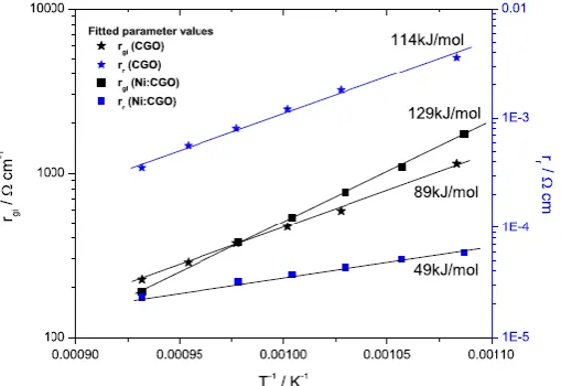
With the development of low temperature SOFC (LT-SOFC), metal supported cells have been developed. Nielsen et al. reported the first detailed impedance characterization of a cermet based anode with Ni:GDC (10wt% Ni in GDC) infiltration in metal-supported SOFCs, and studied the influence of Ni content, the amount of infiltration, backbone composition, impedance evolution during start-up, as well as temperature effects, i. e. sintering of Ni:GDC nano particles.134 It was
found that the addition of a small amount of Ni not only greatly improves performance (the
resistance associated with the surface reaction was lowered by a factor of 10, and activation energy decreased from 114 kJ mol-1 to 49 kJ mol on addition of Ni, shown in Figure 8), but also provided a
[image:16.595.82.337.436.611.2]Ni-GDC matrix in which sub-micron sized Ni particles were trapped in the GDC network which prevented Ni particles from further growth in the temperature range 650-1000 ˚C.
Figure 8 Arrhenius plot of the fitted impedance model parameters for CGO and Ni:CGO infiltrated anodes. Used with permission from Journal of Power Sources 2012, 219, 305-316. Copyright 2012 Elsevier.
Spinel-structured MnFeCrO4 was explored by Stefan et al. as scaffold for a range of materials to seek
potential SOFC electrodes.135 A symmetric cell design with MnFeCrO
4|YSZ|MnFeCrO4 wafer was
used, with the impregnates including LSCM, La0.8Sr0.2FeO3 (LSF), GDC, CeO2 and/or Pd, and were
evaluated both in air as cathode and in humidified 5%H2/Ar as anode. Substantial improvement in Rp
MnFeCrO4/LSCM/CeO2 with and without Pd was observed with prolonged exposure (11 hour) to
humidified 5%H2/Ar at 850˚C, possibly due to ceria sintering and Pd passivation.
Perovskite-type (La,Sr)(Ga,Mg)O3 (LSGM) has been widely applied as electrolyte material for
LT-SOFC, due to its superior oxide ion conductivity over GDC and YSZ at the operating temperature of 500 - 650 ˚C. However, its reactivity with Ni during co-firing means the Ni-based cermet anode supported cell structure difficult to handle. Such a problem can be avoided by infiltrating Ni into the pre-fired LSGM frame. Barnett et al. successfully manufactured a LST anode supported LT-SOC with thin LSGM electrolyte from tape casting, with a La0.6Sr0.4Co0.2Fe0.8O3 (LSCF)-GDC cathode from
screen-printing, and with Ni impregnated into the anode.136 The impregnation of Ni into the LST
anode current collecting layer and LSGM anode functional layer (AFL) was optimised in terms of surface area, porosity, thickness of AFL as well as Ni loading. In the AFL with 30wt% pore former and 12.3 vol.% Ni, the estimated TPB length (calculated from quantitative analysis of 3D reconstruction with FIB-SEM) is ~6 times that of an Ni-YSZ anode supported cell fabrication from a typical co-firing.
Due to its excellent sulfur tolerance and superior redox properties in the intermediate temperature range, the double perovskite SFM has been of interest as alternative fuel electrode in SOCs.105,137 138, 139, 140 As has been mentioned in section 3.1, the infiltration derived SFM-YSZ electrode displayed
remarkable electrochemical performance and fair short-term stability, with avoided solid-state reactions between the two at temperatures lower than 1000 ˚C. When adopted as scaffold,
impregnation with metal, such as Ni, was reported to be effective for enhancing the catalytic activity of SFM-based electrodes. On an LSGM electrolyte, Ni (2 wt%) impregnated SFM anode based cell showed much improved peak power density in wet H2 at 800 ˚C compared to bare SFM anode cell
(1.2 W cm-2 versus 0.7 W cm-2).140 Further, significant improvement in catalytic properties were also
found from Ni impregnated SFM electrodes working in methane atmosphere.139,140 Regarding sulfur
tolerance, it was found that, due to the introduction of catalytically active Ni, significant degradation occurred when the impregnated Ni-SFM anode was exposed to H2 with 100 ppm H2S at 0.7V at 800
˚C, however, this degradation was fully recovered upon removing H2S.
4.
Impregnated Cathodes
Similar to SOFC anodes there is considerable interest in preparing SOFC cathodes by infiltration techniques 141,142,143 and it can be argued that there is greater need to use this approach on the air
electrode side due to the sensitivity to typical air electrodes to reaction with electrolyte or other skeletons at ceramic sintering temperatures
4.1 Infiltration of ion conductive phase
Infiltration of MIEC porous cathode with ion conductive promoters has been found to be an efficient way of creating morphologically altered electrode surface, extending the TPB density and increasing the surface area for ORR reaction143. It has also been shown to increase the oxygen exchange rate
across the surface of the electrode144 and so further increasing the ORR rate. Doped CeO 2 is
routinely used as an ion conducting infiltrate material having higher coefficient of oxide ion conductivity than conventional cathode materials such as LSM and LSCF at intermediate SOFC temperatures 145 (see Figure 9).
The low ionic oxygen conductivity of LSM limits the ORR reaction to the areas close to TBP, hence infiltrating a phase with higher oxide ion conductivity was expected to lead to a significant performance improvement of LSM based cathodes. Jiang et al.94 found that infiltrating LSM cathodes
with GDC at loading levels of 5.8 mg cm−2 (~38 vol%) reduced the polarization resistance of the
cathode drastically to 0.21 Ω cm2 at 700 ˚C which made the performance of the GDC-impregnated
(FASR = ASRblank / ASRinf) was used as figure of merit accounting for the overall cathode polarization
resistance reduction over the baseline “blank” cathode, where area specific resistances (ASR) of the blank electrodes (ASRblank) and the infiltrated electrode (ASRinf) were used as measurable variables.
Whilst such improvement factors have some merit in evaluating enhancements due to the electrode treatment, they do not easily transfer between laboratories and are easily skewed if the “blank” runs are far from optimum, hence we try to focus on absolute values in this review. Such absolute values will tend to favour established materials that have had several years of optimisation but the intrinsic advantage of infiltration is that initial optimisation comes much easier than for bulk composites. Yoon et al.146 achieved a slightly better performance for pure LSM cathode infiltrated with
Sm0.2Ce0.8O2 (SDC) yielding cathode polarization resistance of 0.19 Ω cm2 at 700 ˚C. The effect of
doped ceria infiltration was found to be more pronounced at lower temperatures (~650 ˚C) and for low-frequency responses related to the dissociation and diffusion of oxygen on the LSM electrode surface147 . Similar electrochemical activity enhancement has been reported by several authors on
LSM–YSZ composite cathodes infiltrated with doped ceria142,148,149,150,151,152. The effect of ionic
conductive oxide infiltration at sufficient loading levels has been suggested to be related to the extension of TPB creating an ionic conducting path on top of the LSM particles and on top of the insulating low conducting zirconates at the LSM–YSZ interface 148 both of which enlarged the
electrochemically active portion of the electrode. At the same time non-percolative nano structuring of the electrode surface was also shown to have substantial effect. Jiang et al.147 reported that low
loading level of GDC (~0.72 mg cm−2; 3.1 vol%) can produce enhancement in electrochemical activity,
despite GDC nano particles not forming ionic percolating phase. Ding et al.153 used Sm
0.2Ce0.8O3-∂ to
decorate SDC nanoparticles on a LaNi0.6Fe0.4O3-∂ (LNF) cathode which appeared more tolerant
towards Cr poisoning originating from the stainless steel interconnects than conventional LSM. Infiltration of composite cathodes with oxides that have a wide ranging ion conductivities and catalytic activities (CeO2, SDC, YSZ, CaO142 , Sm2O3151 ) have been shown to produce cathode
[image:18.595.83.519.460.603.2]performance improvements. These observations suggest that the oxide infiltrations cause additional effects such as scavenging of impurities as well as beneficial surface microstructural or chemical modification of the cathode scaffold itself.
Figure 9 Diffusion coefficient (D*) (a) and Surface exchange coefficient (k) (b) for various cathode and electrolyte materials. Reproduced with permission from J. Electrochem. Soc., 1999 146 (4) 1273. Copyright 1999 The Electrochemical Society.
Further reduction of the operating temperature of SOFCs to ~500 ˚C have been expected to allow widespread commercialization of SOFC (e.g. in the household sector for CHP application as well as direct utilization of commercially attractive fuels such as liquid methanol). The appraisals of doped ceria by Steele154 have shown that ceria can maintain predominant ionic conducting in a reducing
ionic conductivity (~1x10⁻¹ S cm-1 at 800 ˚C 156 in air ), lower TEC value (14-15.3×10⁻⁶ K-1 at 373
873 K)155, high surface exchange coefficient (k) and bulk diffusion (D*) coefficient (see Figure 9) 94,145
. A fundamental disadvantage of LSCF is its low structural stability. LSCF based cathodes were found to suffer from substantial long-term degradation, typically at a rate of 0.05% per hour157,158.
Strontium oxide surface segregation is often reported as a major degradation mechanism for LSCF-based cathodes. According to Ding et al.157 the combined effects of reduced surface stress and
smaller surface charge result in SrO-terminated surfaces having lower energy than LaO-terminated surfaces. The enrichment of SrO at the cathode surface causes deactivation of ORR sites and decrease in surface activity. Lowering the operational temperature is a straightforward way to slow down such degradation problems; however, the expected reduction of electro-catalytic activity needs to be counteracted by extending TPB density and minimizing the polarization losses. Introducing an ion conductive nano phase onto the LSCF scaffold via infiltration can enhance TPB length creating higher conduction oxide ion paths and improving the stability of the cathode. A number of studies have shown that the addition of doped ceria can also accelerate the oxygen surface exchange rate. Xia et al. 159,160,161 used electrical conductivity relaxation method and found
that coating LSCF with Sm-doped ceria resulted in an increase by a factor of 10 in the surface exchange rates. The surface exchange coefficient of the SDC coated LSCF was found to be dependent on the conductivity of doped ceria providing additional free oxygen vacancies for the surface exchange reaction. It was suggested that the oxygen exchange process at LSCF/SDC/gas triple phase boundary sites was faster than that taking place on the pure LSCF surface. The infiltration of Gd0.2Ce0.8O2 into screen printed La0.8Sr0.2Co0.5Fe0.5O3-δ was reported by Chen et al.162 to significantly
reduce the polarization resistance values as compared to the pure LSCF cathode from 0.22 Ω cm2 to
0.06 Ω cm2 at 750 ˚C with 1.5 mg cm-2 CGO loading. Nie et al.163 performed infiltration of tape-casted
LSCF6428 cathodes with aqueous nitrate solutions of Sm0.2Ce0.8O1.95 (SDC) precursors and glycine as a
complexing agent. Impedance analysis of LSCF/SDC/8 mol% Y2O3-ZrO2/SDC/LSCF symmetric cells
indicated dramatically reduced polarization losses, from a blank cathode polarization resistance value of 0.15 Ω cm2 to 0.074 Ω cm2 for the infiltrated cathode at 750 ˚C. Enhanced performance and
stability of LSCF cathodes were reported by Liu et al.164 when La
0.4875Ca0.0125Ce0.5O2-δ (LCC) was
applied as a thin-film coating on the scaffold surface. When 5 μL of 0.25M LCC precursor was infiltrated into the LSCF cathode, the cathodic polarization resistance was reduced to 0.076 Ω cm2
from 0.130 Ω cm2 at 750 ˚C. An exception of this trend was the result reported by Zhao et al.165 on
the infiltration of one-dimensional La0.8Sr0.2Co0.2Fe0.8O3-d nanorod-based cathode infiltrated
with Ce0.8Gd0.2O1.9 precursor. A significantly greater reduction in the polarization resistance was
reported, illustrating the importance of the cathode microstructure on the ink dispersion. The nanorod-based scaffold in this case provided optimized “one-dimensional” porosity allowing easier ink penetration and hence higher loading limit for the CGO precursor. Using single step inkjet printing infiltration of CGO in composite LSCF/CGO cathodes Tomov et al.38 reported ASR of 0.17
Ω cm2 measured at 650 ˚C. These values were achieved with very low expenditure of the ink by
sequential infiltration of nL size drops with high lateral resolution in a single step infiltration procedure.
4.2 Infiltration of noble and transition metal promoters
Enhancing the cathode performance at low operational temperature can also be achieved by modification of the cathode scaffold with noble and transitional metal promoters. Introduction of both the noble metal promoters - Pd162,166, Pt167,168, Ag167,169,170 and the low-cost transition metal
promoters - Cu171,172, Ni173, Co174 have been evaluated. The mechanism of metal promotion is not yet
Improvements were generally more pronounced at lower operational temperatures (500-650 ˚C) indicating the potential benefit of cathode infiltration with metal promoters for reduced temperature SOFCs. The effect of metal promoters on SOFC cathode performance was found to be dependent on a complex balance between the enhanced oxygen adsorption/dissociation rate and the interfacial oxygen transfer rate, which could be influenced, in a different degree by the interaction of the metal phase in the MIEC cathode. Serra et al.166 experimented with Pd
impregnation in LSCF and found by XPS that approximately 20% of the Pd is present as metal and the rest exists in oxidised form, presumably incorporated into LSCF B-site. They reported that Pd substitution may accelerate the redox cycles of the charge carriers, Co3+/Co4+and Fe3+/Fe4+, at B-site,
hence improving the reduction of oxygen atoms. Sakito et al. 169 reported enhancement of maximum
output power density by 1.5 times by infiltration of AgNO3 solutions into porous La0.6Sr0.4Co0.2Fe0.8O3
electrodes. In a similar experiment, Huang et al. 167 infiltrated 2 wt.% of Pt, Ag (in metallic state) and
Cu (as oxide) into composite LSCF-GDC cathode and found a promotion trend of Cu > Ag > Pt. As pointed out by the authors, the reactivity for O2 dissociation over Pt was expected to be better than
that of Cu and that of Ag worse than Cu. The discrepancy was assigned to the difference of the oxygen affinities of the metals used and the different influence of the metal promoters on the rate of oxygen transport from the metal surface into the oxygen vacancy in the LSCF lattice. Guo et al.176
pointed out that the effect of metal promoter interaction with the lattice of the oxygen-ion conducting LSCF perovskite could be associated with the size of the metal cation in comparison with that of the A-site or B-site cation in the ABO3 perovskite. The cation radius of Cu3+ (0.68 Å) is well
matched to that of LSCF B-site Co3+ (0.685 Å) assuring good interaction of Cu with the LSCF lattice.
The cation radius of Ag+ (1.29 Å) is close to that of the LSCF A-site La3+ (1.15 Å), also resulting in a
good interaction of Ag with LSCF A-site cations. On the other hand the ionic radiuses of Pd4+ (0.755
Å) or Pt4+cation (0.765 Å), does not provide as close match
with LSCF B-site cations hence the surface interaction can cause local de-stabilization of LSCF lattice. While Sahibzada et al.177 and Simmer et al.178 observed positive
promotion effect of Pd added to LSCF and LSF based cathodes, especially at lower operational temperatures, Haanappel et al.179 found that neither infiltration of the
cathode with Pd solution nor mixing with Pd black resulted in a positive effect. The explanation for these contradictory results could be related to other factors such as the distribution and the size of the promoters, lack of convention on the loading levels measure as well as the non-optimal calcination procedures. As illustrated by Guo et al.176 the loading level of transitional metal
[image:20.595.80.243.397.649.2]oxides and noble metals has an optimum above which the interfacial oxygen transfer can be negatively influenced as the promoting nano particles start to obstruct the interaction sites of interfacial O with the cathode surface oxygen vacancies (See Figure 10).
Figure 10 Schematic diagram of the Cu content on the electrochemical reaction of oxygen over the cathode TPB. The diagrams of a, b and c simulate LSCF-GDC doped with Cu, 1 wt%, 2wt% and 5wt.%, respectively. Reproduced with permission from Fuel Cells 2010, 10, 718. Copyright 2010, Wiley.
A general issue with ORR reaction enhancement via nano-decoration of the cathode surfaces is the inherent instability of nano-structured decorations which tend to agglomerate at operation temperatures due to the large surface energy associated with the nano-sized particles. A systematic comparative study on the stability of MeOx promoted ORR in LSCF based cathodes was performed by Gao et al.180,181 (see Figure 11a) using infiltration of metal nitrate salts (Cu, Ni, Co, Ag) dissolved in
Ethanol with citric acid as additive. After an initial substantial reduction of the polarization resistance all infiltrated cathodes were found to deteriorate at different rates (Vd) with following the tendency
Vd(LSCF+Cu) >> Vd(LSCF+Ni) > Vd(LSCF+Ag) = Vd(LSCF+Co)). After an initial period of accelerated
coarsening leading to distinctively different morphological features, Ag and Co infiltrated samples reached stabilization of ASR values after approximately 100 hours of testing. In comparison, ASR values of Cu and Ni infiltrated polarization resistances were still increasing after 150 hours of testing. While Ag and Co tended to agglomerate at the grain boundaries of the composite LSCF/CGO cathode and likely act as inhibitors in the scaffold grains sintering process, the infiltrated Cu and Ni nano particles were observed to be randomly distributed on the scaffold surface with Cu particles agglomeration significantly larger and non-uniform in size (see Figure 11 b-e).
a)
[image:21.595.85.387.285.638.2]b)
Figure 11 Ageing behaviour of LSCF/CGO cathodes infiltrated with Cu, Ni, Ag and Co promoters – (a) ASR vs aging time at 500 ˚C in air, (b-e) SEM of infiltrated LSCF/CGO cathodes after 150 hours aging 180,181.
The use of Pr0.75Sr0.2MnO3−δ (PSM) and PrSrCoMnO6-δ (PSCM) impregnates on LSFC scaffolds182