ISSN: 2456-1878
Modeling and Simulation of Resistive type
Superconducting Fault Current Limiter
Shilpi Yadav
1, Lini Mathew
2, Kuldeep Singh Rajput
31
ME Student, Electrical Engineering Department, NITTTR Chandigarh, India 2
Associate Professor, Electrical Engineering Department, NITTTR Chandigarh, India
3M.Tech Student, Electrical Engineering Department, DTU Delhi, India
Abstract— For upcoming smart grid one of the most
essential topics regarding the implementation of
Superconducting Fault Current Limiters (SFCL) is associated to its possible outcome on the reduction of abnormal fault Current. Due to the enlarge fault currents level, SFCL is more likely to infiltrate into a medium voltage and low voltage transmission network to lower the capacity of electric devices and improve their stability. Excessive fault current is a serious problem when grid connection of the micro grids with the current power grids, to be solved after implementation of SFCL in the network. SFCL is irresistible solution to limit fault current. Quick protection to the power system is provided by resistive type SFCL model. At present no Simulink model of SFCL has been introduced in the MATLAB library software. In this paper a Matlab/Simulink model for a resistive type SFCL is proposed. This paper first introduces a resistive type SFCL model in Matlab/Simulink and then simulates different types of fault and analysis is done without SFCL and with SFCL. The study shows that SFCL not only reduce the magnitude of fault current to a satisfactory level, but also damp transient recovery voltage. SFCL also improves the power system transient stability, power quality and reliability by reducing the fault current instantaneously.
Keywords— Smart grid, symmetrical faults, Power
quality, SFCL, transient recovery voltage.
I. INTRODUCTION
The requirement of the electricity in the world is increasing at a high rate including India and demand of power is greater than the supply of power due to bigger houses, population growth, air conditioners, bigger TVs and more computers. With the enormous increase on the electricity requirement, the scale of both renewable energy generation
ISSN: 2456-1878
Fig.1:Current during Normal and Faulty Condition [9, 10].
The current during steady state and fault condition with and without SFCL is shown in Fig.1.
II. SIMULATION MODELLING OF AN SFCL
IN MATLAB/ SIMULINK
Matlab/Simulink is used to design and implement the model of Resistive SFCL. There are various parameters out of which four fundamental parameters are used to design Resistive SFCL [11-14]. These parameters are:
• Transition/Response time
• Minimum and Maximum Impedance
• Triggering Current
• Recovery time
The SFCL working voltage is 22.9kV. The SFCL parameters with their values are shown in Table.1. The SFCL model developed in Simulink/SimPower System is shown in Fig.2 SFCL model calculates the RMS value of the flowing current and then compares it with the triggering or critical current which is defined in the Matlab function program [15]. If a passing current is larger than the critical current level and Temperature is below critical temperature
of Yittrium Barium Copper Oxide (YBCO)
superconducting material, then SFCL resistance increases to maximum impedance level in a pre-defined response time otherwise it adds minimum resistance in the circuit. The critical temperature of YBCO superconducting material is 93K or -183ºC. In fault condition, voltage get reduced, controlled voltage source is used to compensate the voltage sag problem [16, 17]. The product of flowing current and impedance is applied as an input to the controlled voltage source. Finally when the flowing current level falls below the critical current level the system waits until the recovery time and then goes into steady state. The important parameter to be given in SFCL is the current limiting
resistance value. It is stored in user Matlab Function program [18].
Fig.2:Model of a Resistive SFCL in Matlab/ Simulink
Table I Fundamental Parameters of AC SFCL [19, 20]
S. No Parameters Value
1. Transition/Response time 2ms
2. Minimum Impedance 0.01Ω
3. Maximum Impedance 20Ω
4. Recovery Time 10ms
5. Triggering Current 550A
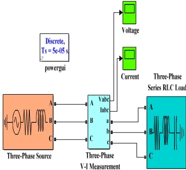
III. SIMULINK MODEL OF THREE PHASE
SYSTEM
The SFCL model is integrated into a power system to simulate its performance in a grid. Here a Simple three phase system is designed in Matlab/Simulink which consists of power source and load [21]. The three phase system is in steady state condition is shown in Fig.3.
ISSN: 2456-1878
IV. RESULT AND DISCUSSION
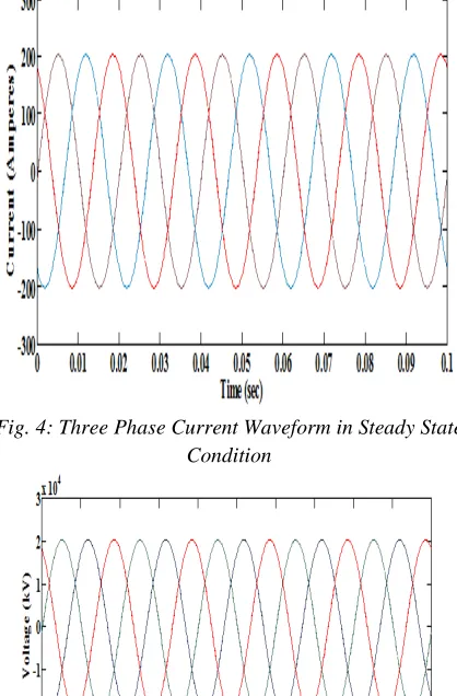
The SFCL reduces the fault current within the first cycle than other devices. The implementation of SFCL in the power system increases the reliability and integrity. In normal condition the magnitude of current and voltage is shown in Fig.4 and Fig.5 respectively. A three-phase to ground fault has been triggered at time 0.1 s and lasts till the end of the simulation [22]. The current and voltage waveform during fault condition without SFCL is shown in Fig.6 and Fig.7 respectively.
Fig. 4: Three Phase Current Waveform in Steady State Condition
Fig.5: Three Phase Voltage Waveform in Steady State Condition
In Fig.6, it could be noted that when there is no SFCL applied in the system, the peak value of the three phase fault current could be as high as about 3kA and in Fig.7 voltage drop to zero in faulty condition.
Fig.6: Three phase Current Waveform during Fault Condition
Fig.7: Three Phase Voltage Waveform during Fault Condition without SFCL
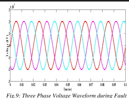
In faulty condition the magnitude of fault current could be high as about 3 kA. This high magnitude of fault current has to be reduced within the rating of protective equipments. This can be achieved by implementing the SFCL in three phase system. After implement the SFCL in the system the peak value of three phase fault current reduced to 400A as shown in Fig.8 and voltage also build up to 20kV as shown in Fig.9 which were reduced to zero in fault condition without SFCL.
ISSN: 2456-1878
Fig.9: Three Phase Voltage Waveform during Fault Condition with SFCL
Table II shows the current limitation rate during steady state condition, fault condition without SFCL and fault with SFCL condition. In steady state condition peak value of current is 200A with and without SFCL, but when fault occurs peak value of current increase upto 3kA. The presence of SFCL reduces the peak value upto 400A.This gives 50% reduction in fault current.
Table II Current Limitation Rate in a Three Phase Simulation System [23-25]
S.NO Item
Current Peak value
under steady state
Current Peak value
during fault
Rate of limitation
1.
without
SFCL 200A 3kA 0%
2.
with
SFCL 200A 400A 50%
V. CONCLUSION
The SFCL is a promising device to limit the increased fault level caused by the expansion of power grid and integration of renewable energy sources. A resistive type SFCL considering the temperature of YBCO superconducting material is developed in the Matlab/Simulink. In this paper SFCL model has been integrated in the simple three phase system consisting source, load and measurement blocks. The simulated current waveforms from this integrated model were analyzed in different operating conditions. The results are tabulated in table which shows that, using SFCL module the transient rise in fault current are suppressed to a desired value using SFCL. From table also conclude that, the resistive SFCL module have ability to limit the sudden rise in fault current by providing the sufficient value of
resistance. The SFCL not only suppress the magnitude of fault current but also compensate the voltage sag during fault condition.
REFERENCES
[1] X. Zhang, H. S. Ruiz, Z. Zhong, and T. A. Coombs, “Implementation of Resistive Type Superconducting
Fault Current Limiters in Electrical Grids:
Performance Analysis and Measuring of Optimal
Locations,” International conference on
superconductivity, Vol.64, pp. 1–18, 2015.
[2] J. Kozak, M. Majka, T. Janowski, and S. Kozak, “Design and Development of the First Polish Superconducting Fault Current Limiter for MV Distribution Systems,” Superconductivity Science Technology, Vol. 36, pp. 845–848, 2012.
[3] H. Kraemer, W. Schmidt, H. Cai, B. Gamble, T. Macdonald, J. Mcnamara, W. Romanosky, N.
Lallouet, F. Schmidt, and S. Ahmed,
“Superconducting Fault Current Limiter for
Transmission Voltage,” Superconductivity Science Technology, Vol. 36, pp. 921–926, 2012.
[4] M. Stemmle, C. Neumann, F. Merschel, U. Schwing, K. Weck, M. Noe, F. Breuer, and S. Elschner, “Analysis of Unsymmetrical Faults in High Voltage Power Systems With Superconducting Fault Current
Limiters,” IEEE Transactions on Applied
Superconductivity, Vol. 17, No. 2, pp. 2347–2350, 2007.
[5] J. Zhu, X. Zheng, M. Qiu, Z. Zhang, and J. Li, “Application Simulation of a Resistive Type Superconducting Fault Current Limiter ( SFCL ) in a
Transmission and Wind Power System,”
Superconductivity Science Technology, Vol. 75, pp. 716–721, 2015.
[6] A. Morandi, S. Imparato, G. Grasso, S. Berta, L. Martini, M. Bocchi, M. Fabbri, F. Negrini, P. L. Ribani, and A. A. Dc-operating, “Design of a DC Resistive SFCL for Application to the 20 kV Distribution System,” IEEE Transactions on Applied Superconductivity, Vol. 20, No. 3, pp. 1122–1126, 2010.
[7] U. A. Khan, J. K. Seong, S. H. Lee, S. H. Lim, and B. W. Lee, “Feasibility Analysis of the Positioning of Superconducting Fault Current Limiters for the Smart
Grid Application Using Simulink and
SimPowerSystem,” IEEE Transactions on Applied Superconductivity, Vol. 21, No. 3, pp. 2165–2169, 2011.
ISSN: 2456-1878
Shin, J. Seong, J. Lee, Y. Kim, and B. Lee, “Validity Analysis on the Positioning of Superconducting Fault Current Limiter in,” IEEE Transactions on Applied Superconductivity, Vol. 23, No. 3, pp. 3–6, 2013. [9] P. Mahajan, P. J. Shah, and R. Saxena, “Analysis of
smart grid with superconducting fault current limiters,” International Journal of Science, Spirituality, Business and Technology Vol. 3, No. 2, pp.87-92, 2015.
[10] S. Nemdili and S. Belkhiat, “Modeling and Simulation of Resistive Superconducting Fault-Current Limiters,” J Supercond Nov Magn, pp. 2351–2356, 2012. [11] I. Normal and S. Eckroad , “Superconducting Fault
Current Limiters,” Electric power research institute
2009, Available:
http://www.suptech.com/pdf_productsfaultcurrentlimit ers.pdf.
[12] S. M. Blair, S. Member, C. D. Booth, G. M. Burt, A. Superconducting, and A. S. M. Requirements, “Current – Time Characteristics of Resistive Superconducting Fault Current Limiters,” Vol. 22, No. 2, pp. 1–5, 2012.
[13] J. Bock, A. Hobl, J. Schramm, S. Krämer, and C. Jänke, “Resistive Superconducting Fault Current Limiters Are Becoming a Mature Technology,” Vol. 25, No. 3, pp. 2–5, 2015.
[14] O. Placement, “International Journal of Engineering Optimal Placement and Sizing of Fault Current Limiter in a Real Network : a Case,” Vol. 28, No. 3, pp. 402–409, 2015.
[15] S. M. Blair, S. Member, C. D. Booth, G. M. Burt, and C. G. Bright, “Application of Multiple Resistive Superconducting Fault-Current Limiters for Fast Fault Detection in Highly Interconnected Distribution Systems,” Vol. 28, No. 2, pp. 1120–1127, 2013. [16] E. Blog and C. Us, “Application and Effects in Power
System Superconducting Fault Current Limiters- - Avinash Babu K M and,” 2016.
[17] S. Kar, S. Kulkarni, S. K. Sarangi, and V. V Rao, “Conceptual Design of a 440 V / 800 A Resistive-Type Superconducting Fault Current Limiter Based on High T c Coated Conductors,” Vol. 22, No. 5, 2012. [18] H. Choi, S. Lim, D. Chung, B. Han, O. Hyun, and T.
Sung, “Responses of Resistive,” Vol. 15, No. 2, pp. 2035–2038, 2005.
[19] Z. Hong, J. Sheng, L. Yao, J. Gu, and Z. Jin, “The Structure , Performance and Recovery Time of a 10 kV Resistive Type Superconducting Fault Current Limiter,” Vol. 23, No. 3, pp. 3–6, 2013.
[20] O. Naeckel and M. Noe, “Design and Test of an Air
Coil Superconducting Fault Current Limiter
Demonstrator,” Vol. 24, No. 3, 2014.
[21] M. J. Reddy, M. T. Scholar, and E. Engineering, “Positioning of Superconducting Fault Current Limiters for the Smart Grid Application Using Simulink,” Vol. 3, No. 3, pp. 213–220, 2015.
[22] S. B. Rhee, J. K. Lee, and B. W. Lee, “Impacts of Superconducting Fault Current Limiters on the Recloser Operation in Distribution Electric Power Systems,” Vol. 21, No. 3, pp. 2197–2200, 2011. [23] H. Kim, S. Yang, S. Yu, H. Kim, B. Park, Y. Han, K.
Park, and J. Yu, “Development and Grid Operation of Superconducting Fault Current Limiters in KEPCO,” Vol. 24, No. 5, pp.1-5, 2014.
[24] H. Kim, S. Yu, H. Kim, W. Kim, S. Yang, J. Lee, and O. Hyun, “Demonstration of a Superconducting Fault Current Limiter in a Real Grid,” Vol. 23, No. 3, pp. 0– 3, 2013.
[25] Z. L. Chen, W. Z. Gong, A. L. Ren, M. R. Zi, Z. Q. Xiong, D. J. Si, and F. Ye, “Prospective of Applications of Superconducting Fault Current Limiters in Chinese Power Grids,” Vol. 36, pp. 894– 901, 2012.