1. Introduction
Major objective behind installed series capacitor in long EHV transmission line is to optimize electrical en-ergy system operation. Several advantages of employed this technology have been frequently addressed in the lit-erature [1]-[2]. Presence of the series capacitor in the fault loop impedance creates the immediate change in the volt-age and current waveforms and this case of fault may causes voltage and current inversion problems in power system protection [3]-[4]. Typically, the series capacitor is protected from over voltage damage specially, during a heavy fault current by the metal oxide varistor (MOV) with nonlinear characteristic and bypass breaker. Hence, un-estimated behavior of the series compensated protec-tive equipment also increase the complexity of the direc-tional protection decision [5]-[6].
Directional relays are extensively utilized in power system these days in order to enhance the reliability and selectivity of the protection schemes. The voltage and cur-rent inversion events in the series compensated lines are common critical concerns of the directional relaying. In the series compensated line, the overall fault loop imped-ance may be capacitive for some fault situations. This is
in contrast to the ordinary lines where fault current leads the voltage by nearly 90 degree and called current inver-sion condition. Thus, the current inverinver-sion causes the con-ventional relay to see a fault in the protected line to be in a reverse direction. In this condition, the series capacitor reactance is more than the inductive reactance summation of the faulted line and source impedance. However, the chance of the current inversion is rare for the high com-pensation level and low source impedance for near relay fault cases [6]-[7].
A current based technique based on wavelet transient features has been presented for series compensated par-allel lines [7]. The fault direction can be identified, by comparing the polarities of wavelet coefficients of the branch currents. Although, the applied scheme is capable of correctly identifying the fault directions irrespective of voltage and current inversion. But it has limitation to op-erate in noisy environment due to using high frequency fault transient.
One solution to current inversion problem can be ob-tained by using the incremental voltage to current ratio technique [8]-[9], with employing a current inversion de-tector. A new directional relaying based on positive se-quence voltage and current has been proposed for series compensated lines [10]-[11]. The current inversion con-dition is detected using change in positive sequence of voltage magnitude. Robustness to voltage inversion de-spite using voltage component is an attractive point in that study. But, the proper operation of the relay depends to
Current Directional Protection of Series Compensated
Line Using Intelligent Classifier
M. Mollanezhad Heydarabadi*and A. Akbari Foroud *(C.A.)
Abstract: Current inversion condition leads to incorrect operation of current based directional relay in power
system with series compensated device. Application of the intelligent system for fault direction classification has been suggested in this paper. A new current directional protection scheme based on intelligent classifier is proposed for the series compensated line. The proposed classifier uses only half cycle of pre-fault and post fault current samples at relay location to feed the classifier. A lot of forward and backward fault simu-lations under different system conditions upon a transmission line with a fixed series capacitor are carried out using PSCAD/EMTDC software. The applicability of decision tree (DT), probabilistic neural network (PNN) and support vector machine (SVM) are investigated using simulated data under different system con-ditions. The performance comparison of the classifiers indicates that the SVM is a best suitable classifier for fault direction discriminating. The backward faults can be accurately distinguished from forward faults even under current inversion without require to detect of the current inversion condition.
Keywords:Series compensated transmission line, Current inversion condition, Directional protection,
In-telligent classifier.
Iranian Journal of Electrical & Electronic Engineering, 2016. Paper first received 15 April 2016 and accepted 26 January 2017. The Authors are with the Faculty of Electrical and Computer Engineer-ing, Semnan University, Semnan, Iran
E-mails: [email protected], [email protected] Corresponding Author: A. A. Foroud
detect of the current inversion condition.
The current based directional protection techniques [12]-[13] based on simple mathematical methodologies have been presented for uncompensated lines. For the case of series compensated protection application, al-though these linear methods weren’t affected by voltage inversion due to use no post fault voltage signal. But, they fail under current inversion fault cases. In result, require to a nonlinear system is necessary for solving this problem for the current directional relay.
Recently, an intelligent technique based on artificial neural network (ANN) [14] and combined wavelet trans-form and ANN [15] has been suggested for directional protection. The above approaches are sensitive to system frequency changes, requiring large training sets, training time, and a large number of neurons. Moreover, wavelet based feature extraction method [13] finds limitations as wavelet transform is highly susceptible to noise signal.
To overcome the current based directional protection problems, an effective intelligent classifier is proposed in this paper. The SVM classifier is introduced for fault di-rection classification of the series compensated lines. In this method, one cycle current samples including the half cycle of pre and post fault current samples at the relaying end are used as input data to the classifier for distinguish-ing the backward faults from the forward faults. In order to verify the proposed method, different faults simulations have been performed upon a typical 400-kv, 325-km power system using PSCAD/EMTDC [14]. Simulated backward and forward faults include different system sce-narios such as variation in fault location, fault inception angle and fault resistance at both of the pre-fault power flow directions for all fault types. The performance of the proposed protection schematic are evaluated under current inversion condition, fault type, high fault resistance, close in fault, air gap breaker operation. Also, the proposed cur-rent directional relaying is perfectly robust for the voltage and current inversion problems.
2. Power System Model
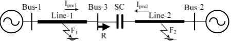
A 400-kV, 50-Hz power system is simulated using EMTDC/PSCAD software [16] for directional protection study in this paper. Already, this model was used to inves-tigate the current inversion condition [10]. As shown in Fig. 1, the power system consists of two sources con-nected by a transmission line included two segments (Line-1 & Line-2). Line-2 is 70% compensated by a fixed
series capacitor. A directional relay located at bus-3. For fault studies, three phase current signals of the relaying end are taken at sampling frequency of 800 Hz with base frequency of 50 Hz (16 samples per cycle). Detail of sim-ulated power system together with series compensator’s data have been presented in Appendix [10].
3. Current Inversion Problem
Directional elements are installed in power system to identify the fault direction for isolating damaged section from other healthy parts and also supervising on distance and over current relays. For transmission lines equipped by series compensated devices, in a fault case in individ-ual system condition including series compensator, meas-ured current may lead the voltage by 90۫ at directional relaying. In this case, overall fault loop impedance is ca-pacitive. In conclusion the relay sees a forward fault in a backward direction. The above problem is called as cur-rent inversion condition in series compensated transmis-sion line protection.
In [10], a current based polarizing directional technique has been used the phase angle difference between the fault current and pre-fault current component to indicate the current inversion effect on operation of traditional direc-tional relays. Three fault cases at different locations but with similar condition (a-g fault type, fault resistance 20Ω and fault inception time 540ms) have been simulated using studied series compensated line shown in Fig. 1. The normal power flow is assumed in direction Ipre-1. Fig. 2 indicates three phase fault currents at relaying end and corresponding positive sequence current angle differ-ence for (a) backward fault, (b) forward fault and (c) for-ward fault with current inversion condition. As shown in Fig. 2, the positive angle difference for the backward and forward fault are positive and negative, respectively. But, this polarizing value for the forward fault with current in-version (c) is positive. However, the current based polar-izing method is not satisfactory for current inversion and it requires detecting the current inversion. In [9], this problem was solved using magnitude of the voltage com-ponent. But, used voltage signals in algorithm make it sensitive to other directional problems such as CVT tran-sient limitation and close in fault effect.
More fault studies by current directional relays based on linear mathematical methods [12]-[13] indicate these approaches fail for current inversion events. However, in the next section, a current directional relaying based on intelligent technique will be proposed to solve the men-tioned current directional problem with nonlinear charac-teristic.
4. Proposed Protection Methodology
The current directional protection of the series com-pensated line has been very challenging task. In this study, an intelligent based classifier has been proposed for fault Fig. 1.The power system model.
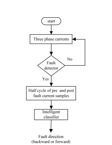
direction discriminating using current signals in power system. The structure of the proposed scheme has been shown in Fig. 3. The three phase currents at the directional relaying bus are retrieved for establishing the proposed protection task. As shown, a fault detector block is con-sidered to determine the fault inception time and activate the intelligent classification. This module responds to the change in magnitude of the difference between the present current component and two previous cycles [17]. A threshold value (0.04 pu) is selected for reliable operation of the fault detector process under non-fault phenomena such as switching events.
After fault transient detection, the half cycle current samples from the pre-fault and post fault inception (3 phases× (8 samples×2 half cycles) = 48 samples) are used as an input data to an intelligent classifier, as shown in Fig. 3. The classifier output determines the fault direction as whether fault direction is backward or forward.
There are different types of intelligent system which have been applied in power system protection. The select-ing of the most suitable classifier is an important task, be-cause the applications of them are different. The performance of a classifier is affected by many factors such as the number of classifier input and output data and the number of training samples. In this research, the abil-ity of the PNN, DT and SVM techniques to classify the fault direction will be investigated using simulation data
Fig. 2. Three phase currents and corresponding positive sequence angle difference. (a) Backward fault. (b) Forward fault. (c) For-ward fault with current inversion
Fig. 3.Structure of the proposed directional protection.
In the next sections, a brief description of these three clas-sifiers including their applications, advantages and disad-vantages have been presented. Due to space limitation, details of each of them have been ignored in this study.
4. 1. Probabilistic Neural Network
The PNN at first was proposed by Donald Specht in 1988 [18]. The PNN is one type of the artificial neural network for nonlinear classifying which approaches the Bayes optimal decision boundaries. The PNN operates using spherical Gaussian radial basis functions centered at each training vector. The architecture of a PNN model is composed of the radial basis layer and the competitive layer.
The main advantages of the PNN is that it is easy to add new categories, or new training inputs, into the al-ready running structure, which is good for the real time applications. Above PNN properties lead to its extensive employing in power system protections [19].The PNN classifier needs to determine only one parameter as smoothing parameter (δ) for tuning the classifier.
4. 2. Decision Tree
The DT is fundamentally based on dividing a difficult decision making process into a sequence of simple deci-sions. Some purposes of the training process in DT tech-nique are: classify correctly as much of the training data as possible, be able to easily update as more training data become available, and have a simple configuration as pos-sible [20].
The DT application for fault type classification of par-allel transmission line has been reported in [21]. The high classification accuracy results have been found from that research using the DT technique. No need to any param-eters and having simple structure make it as suitable tool in the power system protection schematics.
4. 3. Support Vector Machine
SVM is a novel computational learning technique based on the statistical learning theory. In classification applications, the SVM finds out a hyper-plane to map a set of data into two classes so that the margin between the sets is a maximum. The nonlinear transformation is per-formed indirectly using kernel functions such as linear, polynomial, radial basis function and sigmoid.
In the recent years, the SVM scheme has been applied as a suitable pattern-recognition tool for power system protection purposes [22]. The performance of the SVM classifier isn’t limited by the number of input features. Also, it has separation ability between the data sets even very close to each other. Hence, the SVM is suitable tool to apply directly on features without preprocessing the original data and feature selection.
5. Performed Algorithm and Results Discussion
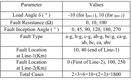
Commonly, the performance of the intelligent based techniques in classification application researches is eval-uated using a data set of different fault simulation cases. Simulation fault cases should be included all of the situ-ations caused by parameter variation of studied system which may occurrence. Then, simulation data are divided into a training set and test set for classification purposes. In this paper, extensive fault cases are simulated upon studied model Fig. 1 using PSCAD/EMTDC. This soft-ware has a powerful ability in power system transient monitoring. In Table 1, different considered system pa-rameters have been presented for 1800 fault simulations. All ten types of faults with different fault resistances, load angles, fault inception angles, and fault locations are sim-ulated. Fault inception angles also were examined over the entire cycle.
It is an important notice that the performance of the proposed technique should be evaluated under the current inversion conditions. Moreover, in order to validate the effectiveness the proposed technique, other fault situa-tions have been also considered. Hence, as observed in Table 1, the system parameters have been selected so as the simulated fault cases involve different system condi-tions as follow below:
o Current inversion condition o Power flow revers
o Close-in fault cases o High fault resistance
o Far from relay location faults o Different Fault types
According to relay direction in Fig. 1, all of the simu-lated faults in line-1 (F1) and line-2 (F2) are considered as backward and forward fault category, respectively. However, the number of backward and forward faults is 720 and 1080 in Table 1, respectively. As already men-tioned, in order to select the best effective classifier, the
Parameter Values
Load Angle į (° ) -10 (for Ipre-1), 10 (for Ipre-2)
Fault Resistance () 0, 10, 100
Fault Inception Angle ( ° ) 0, 45, 90, 120, 180, 270
Fault Type a-g, b-g, c-g, ab-g, bc-g, ca-g,
ab, bc, ca, abc Fault Location
at Line-1(Km)
10, 40 (end of Line-1)
Fault Location at Line-2(Km)
0 (First of Line-2), 100, 250
Total Cases 2×3×6×10×(2+3)=1800
Table 1.System Parameters for Simulation Set
performance of each mentioned classifier should be in-vestigated using simulation data set. Firstly, each of three introduced classifier are trained using half data set (48×900). Also, the fault direction class (backward or for-ward) corresponding fault cases are considered as target vector for classification task. Subsequently, their perform-ance will be tested upon remaining 900 fault cases. In re-sult, the excellent classifier can be determined using results comparison of the classification accuracies.
To perform classification of the fault direction, PNN, DT and SVM have been employed using MATLAB soft-ware, CART software [23] and Lib-SVM toolbox [24] in MATLAB environment, respectively. Experimentally, the parameter δ = 0.5 has been determined for training of the PNN classifier in this study. Similar application of the SVM for power system protection [22] indicates that the RBF kernel function was found to be the most suitable in comparison to other kernel functions. Hence, The Gauss-ian RBF has been selected as the kernel function for fault direction classification in this paper. Generally, the SVM parameters are regularization constant (C) and the width of the Gaussian function (б). A common method to tune the parameters is to use cross-validation to select the best parameters from a pre-selected set [25]. The best results were achieved by selecting C = 4.2606 and б = 1.0011 in this pattern recognition.
After training the three classifiers using training data set, each of them are tested upon testing data set. Classi-fication results obtained by classifiers are summarized in Table 2. According to the classification results obtained, it is observed that the proposed technique gives highly ac-curate results using all classifiers (more than 90%). As shown in table, the accuracy result of the SVM classifier (97.56) is higher than other two classifiers. Therefore, the SVM technique was superior in distinguishing the back-ward faults form the forback-ward faults. In the next parts, the effectiveness of the proposed technique will be investi-gated for different system conditions which have adverse effects on the directional protection schemes.
5.1. Result for Current Inversion
As already mentioned, discriminating between back-ward faults and forback-ward faults even under current inver-sion condition was main objective in this study. Therefore, the performance of the proposed method is evaluated
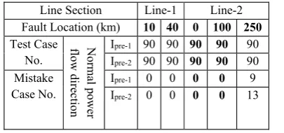
under current inversion condition. The probability of the current inversion occurrence depends to source imped-ances, compensation rate, fault location and fault resist-ance. Table 3 demonstrates testing results for different fault locations in line-1 and line-2 at both normal power flow directions. As shown in this table, there are number of 90 testing cases for each fault location and power flow direction in two above rows. The below two rows present the number of mistake predication cases for each location which are resulted by directional classifier. According to this issue that fault path is capacitive in current inversion, it is expected that this situation may occurs for fault cases in line-2 (0 & 100 km) at power flow Ipre-1. As observed in this table, the proposed classifier correctly classifies all of the 90 testing case without any mistake for mentioned locations. So, the proposed intelligent classifier is not af-fected by current inversion condition. There is a success-ful potential based on the training and testing process behind the intelligent classifier to recognize the backward faults from the forward faults, even under current inver-sion condition.
5. 2. Results for Different Fault Types The sequence directional based relaying [10] is
ade-quate for the all of the ten fault types. The proposed tech-nique is directly fed by three phase current samples without using sequence components. Hence, the perform-ance of the proposed method should be tested on all of the fault types. Table 4 presents classification results for dif-ferent fault type categories. Achieved results indicate that proposed technique satisfy all of the fault types with ac-curacy more than 94%. The acac-curacy of the L-g fault type is lowest (94.33). This is due to the fact that for L-g fault type, only one phase (⅓ of input features) has effective role to determine the fault direction.
5. 3. Performance for High Fault Resistance The high fault resistance has negative effect on some directional relays such as positive sequence relying
Classifier Accuracy (%)
PNN 92.33
DT 95.44 SVM 97.56
Table 2. Testing Results of Different Classifiers
Line Section Line-1 Line-2
Fault Location (km) 10 40 0 100 250
Test Case No.
Normal
p
ower
flow di
re
ction
Ipre-1 90 90 90 90 90
Ipre-2 90 90 90 90 90
Mistake Case No.
Ipre-1 0 0 0 0 9
Ipre-2 0 0 0 0 13
Table 3. Classification Results for Different Fault Locations
method. Increase in fault resistance reduces phasor change of the positive sequence current and it makes a sensitive reliability in the protection decisions [10]. In order to in-vestigate the effect of fault resistance on the operation of the classifier, simulations were carried out with faults sim-ulated on different resistance up to 100 Ω. However, the classification results are sorted with different fault resist-ances and which have been presented in Table 5. From this table it is found that the classifier operates correctly for low fault resistance and classifier mistakes include test cases with high fault resistance. Directional protection of high fault resistance faults far from relay is a very difficult for conventional directional relays. According to Table 3 and Table 5, it can be understood that the proposed
method correctly identifies the high fault resistance faults far from relay with accuracy of 92.67.
5. 4. Close in Fault Effect
When a three phase short circuit fault occurs at near to the directional relay, the measured relay voltage drops. This phenomenon has been called as close in fault effect
and lead to appear the failure in the conventional direc-tional relay operation. Table 3 indicates that the fault test cases in near relay locations (end of line-1 and first of line-2)) are quite identified using the proposed method. It is due to this reason that no voltage signal has been used in the proposed technique.
5. 5. Effect of Air Gap Breaker Operation Commonly, a series compensator is protected against
Fault Type L-g LL-g LL LLL
Test Case No.
270 270 270 90
Mistake Case No.
17 5 0 0
Accuracy (%)
94.33 98.33 100 100
Table 4.Testing Results for Different Fault Types
Fault Resistance ()
0 10 100
Test Case No. 300 300 300
Mistake Case No.
0 0 22
Accuracy (%) 100 100 92.67
Table 5. Testing Results for Different Fault Resistances
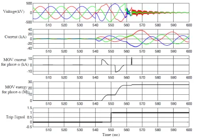
Fig. 4.The voltages, currents, ‘phase-a’ MOV current and ‘phase-a’ MOV energy during three phase fault
fault over voltage by the MOV and the air gap circuit breaker. The operation of the over voltage protection de-vice especially during heavy asymmetrical faults creates several complicities for the conventional protection scheme [26]. In this abnormal system condition, the cur-rent signal seen by relay have significant secondary tran-sient due to the automatic firing the air gap. As a sample, a short circuit fault at after series capacitor (F2 in power system Fig. 1) has been simulated. The three phase volt-ages and currents at relay location, the current and energy of the MOV for “phase-a” and trip signal sent by direc-tional classifier have been shown in Fig. 4. The fault in-ception time is 540ms and during the fault, MOV conducts at every half cycle. As shown in Fig. 4, when the MOV energy reaches to a dangerous level (25Mj), the air gap is fired at cycles later (564ms) for over voltage protection. Since the proposed scheme acts based on the transient signals observed within half cycle post fault (550ms), the decision making process is not affected by the secondary transients due to bypass breaker operation.
5. 6. Enhanced Protection Speed
The computational time of the protection schematics has a very important role in the protection speed. In this study, the SVM processing time (with 48 input features) for a particular fault test case is 18 ms. Therefore, the re-sponse time of the proposed methodology by considering half cycle post fault data (10 ms) is 28 ms. The algorithm has been processed on a notebook computer with hard-ware information Core-i3, CPU 2.3 GHz and RAM 4 GB. As presented in this study, the proposed method was designed based on half cycle pre and post fault current samples. With a purpose to enhance the operation speed of the algorithm based on reducing the input features, the proposed technique will be repeated using only half cycle post fault data (24 samples as input data). The proposed method is repeated on new input features. The response time in this stage is lower than latter examination (13+10= 23ms). Hence, the speed of the protection scheme can be enhanced using only half cycle post fault data. But, the classification accuracy obtained by these lower input sam-ples has been found to be 96.11%. The new achieved ac-curacy is only approximately 1.5% lower than latter reported performance (97.56% for 48 samples). The rea-son of this difference in accuracy is the existence of ef-fective current directional properties in the pre fault signals. The attractive notice in this paper is that the ac-ceptable efficacy was also resulted using only half cycle post fault current samples.
5. 7. Comparison with Conventional Protection Scheme
The voltage and current signals during fault occurrence in series compensated lines contain different frequency components and high frequency noise due to presence the
series compensator and nonlinear behavior of the MOV in the fault loop impedance. The conventional directional relays [9]-[10] often apply Fourier transform and least square error for estimating the fundamental voltage and current phasors. Hence, due to presence non-stationary and non-periodic signals in these types of power system, the traditional signal processing method may not give sat-isfactory results for digital directional relaying. In com-pare to conventional relaying, the proposed algorithm only used current data directly without any pre-process-ing.
6. Conclusion
In this paper, a current directional protection scheme based on intelligent technique was suggested for a series compensated transmission line. The proposed scheme takes only half cycles of the pre and post fault currents at relaying bus as input data to the directional classifier. The PNN, DT and SVM classifiers were selected to discrimi-nating the backward faults from the forward faults.
To evaluate the performance of the proposed method various faults have been simulated under different fault locations, different fault resistances and different fault in-ception angle for all ten fault types. The comparison of the classification accuracies indicated that SVM technique was best tool for this application. Test results showed the effectiveness of the proposed algorithm to directional pro-tection problems such as current inversion, fault type ef-fect, high fault resistance and close in fault and compensator protection reaction. Although the voltage in-version and CVT transient problems weren’t studied in this research, but the proposed method is not affected by these directional problems. It is evident that these events have adverse effects on the measured relay voltage and no voltage signal has been used in the proposed algorithm. In conclusion, the proposed directional technique based on intelligent system has a feasibility to apply on the dig-ital directional relay.
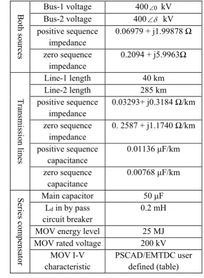
APPENDIX
Table 6 summarizes the detail parameters of the series compensated transmission line used in this study shown in Fig. 1. The two line sections have been represented by the ‘Bergeron’ line model.
References
[1] A. G., Phadke, “Computer Relaying for Power Sys-tems”. New York: Wiley, 1988.
[2] W. A., Elmore, “Protective Relaying Theory and Applications”, 2nd ed. New York: Marcel Dekker, 2003.
[3] IEEE Guide for Protective Relay Application to Transmission-Line Series Capacitor Banks, IEEE Standard C37.116, 2007.
[4] S. M., Hashemi and M., Tarafdar Hagh, “A Novel
Backup Distance Protection Scheme for Series-Compensated Transmission Lines”, IEEE Transac-tions on Power Delivery., Vol. 29, No. 2, pp. 600–707, 2014.
[5] P. M., Anderson, “Power System Protection”. New York: IEEE Press, 1999.
[6] B., Vyasa, R. P., Maheshwarib and B., Dasb, “Pro-tection of series compensated transmission line: Is-sues and state of art”, International Journal of Electrical Power & Energy Systems, Vol. 107, pp. 93–108, 2014.
[7] N., Perera and A. D., Rajapakse, “Series-compen-sated double-circuit transmission-line protection using directions of current transients”, IEEE Trans-actions on Power Delivery, Vol. 28, No. 3, pp. 1566–75, 2013.
[8] G., Ziegler, “Numerical Distance Protection Prin-ciples and Applications”, John Wiley & Sons, 2011. [9] P. G., McLaren, E., Dirks, R. P., Jayasinghe, I. Fer-nado, G. W. Swift, and Z. Zhang, “A positive se-quence directional element for numerical distance relays”, Developments in Power System Protec-tion, Sixth International Conference on (Conf. Publ. No. 434). IET, pp. 239–242, 1997.
[10] P., Jena and A. K., Pradhan, “A positive-sequence
directional relaying algorithm for series-compen-sated line”, IEEE Transactions on Power Delivery, Vol. 25, No. 4, pp. 2288–2298, 2010.
[11] P., Jena and A. K., Pradhan, “Directional relaying in the presence of a thyristor-controlled series ca-pacitor”, IEEE Transactions on Power Delivery, Vol. 28, No. 2, pp. 628–636, 2013.
[12] M. M., Eissa, “Current directional protection tech-nique based on polarizing current”, International Journal of Electrical Power & Energy Systems, Vol. 44 No. 1, pp. 488–494, 2013.
[13] M. M., Eissa and M. M. A., Mahfouz “New high-voltage directional and phase selection protection technique based on real power system data”, IET Generation, Transmission & Distribution, Vol. 6, pp. 1075–1085, 2012.
[14] A.,Yadav and A. S., Thoke, “ANN based direc-tional fault detector/classifier for protection of transmission Lines”, International Journal of Com-puter Science and Information Technology, Vol. 2, No. 5, pp. 2426–2433, 2011.
[15] A., Yadav and A., Swetapadma, “A single ended di-rectional fault section identifier and fault locator for double circuit transmission lines using com-bined wavelet and ANN approach”, International Journal of Electrical Power & Energy Systems, Vol. 69, pp. 27–33, 2015.
[16] PSCAD/EMTDC Power Systems Simulation Soft-ware Manual, Winnipeg, MB, Canada, 1997. [17] Available: www.gedigitalenergy.com /products/
manuals/ d60/d60man-f5.pdf
[18] D. F., Specht, “Probabilistic neural networks for classification, mapping, or associative memory”, IEEE international conference on neural networks, San Diego, CA, Vol. 1, No. 24, pp. 525–532, 1988. [19] M., Mollanezhad Heydarabadi and A., Akbari Foroud, “Accurate fault classification of transmis-sion line using wavelet transform and probabilistic neural network”, Iranian Journal of Electrical and Electronic Engineering, Vol. 9, No. 3, pp.177–188, Sep. 2013.
[20] L., Breiman, J., Friedman, C. J., Stone, and R. A., Olshen, Classification and Regression Trees, Chap-man & Hall/CRC, 1984.
[21] A., Jamehbozorg and S. M., Shahrtash, “A decision tree-based method for fault classification in dou-ble-circuit transmission lines”, IEEE Transactions on Power Delivery, Vol. 25, No. 4, pp. 2184–2189, 2010.
[22] Z., Moravej, M., Pazoki and M., Khederzadeh, “New pattern-recognition method for fault analysis in transmission line with UPFC”, IEEE Transac-tions on Power Delivery, Vol. 30, No. 3, pp. 1231– 1242, Jun. 2015.
[23] D., Steinberg and P., Colla, “CART: Classification
Bot
h sources
Bus-1 voltage 4000 kV
Bus-2 voltage 400G kV
positive sequence impedance
0.06979 + j1.99878
zero sequence impedance
0.2094 + j5.9963
Tr an smi ssi on li nes
Line-1 length 40 km
Line-2 length 285 km
positive sequence impedance
0.03293+ j0.3184 /km
zero sequence impedance
0. 2587 + j1.1740 /km
positive sequence capacitance
0.01136 ȝF/km
zero sequence capacitance
0.00768 ȝF/km
Se
ries comp
en
sat
or
Main capacitor 50 ȝF
Ld in by pass circuit breaker
0.2 mH
MOV energy level 25 MJ
MOV rated voltage 200 kV
MOV I-V characteristic
PSCAD/EMTDC user defined (table)
Table 5. Testing Results for Different Fault Resistances
and Regression Trees, San Diego, CA: Salford Sys-tems”, 1997.
[24] C. C., Chang and C. J., Lin, “LIBSVM-A Library for Support Vector Machines”, ACM Transactions on Intelligent Systems and Technology (TIST), Vol. 2, No. 3, pp. 27. 2011.
[25] C. J. C., Burges, “A tutorial on support vector ma-chines for pattern recognition”, Data Mining Knowl. Discov., Vol. 2, No. 2, pp. l21–167, 1998. [26] D., Nvosel, A., Phadke, M. M., Saha and S.,
Lind-hal, “Problems and solutions for microprocessor protection of series compensated lines”, Develop-ments in Power System Protection, Sixth Interna-tional Conference on (Conf. Publ. No. 434). IET, pp. 18–23, 1997.
M. Mollanezhad Heydar-Abadi was born in Tehran, Iran, in 1984. He received the B.Sc degree in Electrical engineering from the Birjand University in 2007 and M.Sc. degree from Semnan Uni-versity in 2013. His areas of interest include power system protection, transient simulations and digital relays.
Asghar Akbari Foroud was born in Hamadan, Iran, in 1972. He re-ceived B.Sc. degree from Tehran University and M.Sc.and Ph.D de-grees from Tarbiat-modares Uni-versity, Tehran, Iran. He is now with Semnan University. His research interests in-clude power system operation, restructuring, distri-bution systems and distributed generation and power quality.