Volume 2, Special Issue 1 MEPCON 2015
141 Available online at www.ijiere.com
International Journal of Innovative and Emerging
Research in Engineering
e-ISSN: 2394 - 3343 p-ISSN: 2394 - 5494
Review on Study of Solar Powered Adsorption
Refrigeration System
.
Sneha Patil
a, S.G,Dambhare
aaME Heat Power Engineering1, Department of Mechanical Engineering PVPIT , Bavdhan ,Pune bAssistant Professor 2, Department of Mechanical Engineering PVPIT , Bavdhan ,Pune
ABSTRACT:
The sun is an outstanding energy source for mankind. It is clean and comes to the earth for free. In recent years, increasing attention is being given to the use of waste heat and solar energy in energizing refrigerating systems. Solar powered refrigeration and air-conditioning have been very attractive during the last twenty years, since the availability of sunshine and the need for refrigeration both reach maximum levels in the same season. Conventional cooling technologies are generally based on the electrically driven refrigeration system. These systems have several disadvantages: they require high levels of primary energy consumption, causing electricity peak loads and employ refrigerants with negative environmental impacts. Solar adsorption refrigeration is an option to overtake the drawbacks of the conventional cooling system. The adsorption refrigeration is based on the evaporation and condensation of a refrigerant combined with adsorption. This project will describes the design and fabrication of the experimental chamber, the experimental procedure and its feasibility towards development of an alternative eco-friendly refrigeration cycle for replacement of chlorofluorocarbons. The objective of this project is to establish an alternative eco-friendly refrigeration cycle for producing a temperature usually encountered in a conventional refrigerator. By manufacturing such type of refrigerator adds new dimension to the world of refrigeration. This refrigerator gives some amount of relief to the refrigeration world by making it independent of electric power supply and zero running cost.
Keywords: Adsorbent; Refrigerant; Solar Energy; Adsorption; Refrigeration
I. INTRODUCTION
Environmental-friendly means of air-conditioning and refrigeration are attracting a lot of attention nowadays since traditional methods such as vapour compression cycles require consumption of expensive electric energy and are responsible for emission of green house gases. Adsorption air-conditioning is an attractive alternative to the latter-mentioned methods. The emphasis when reviewing the research was on the design, evaluation and cost effectiveness of the prototypes.
II. AVAILABLE SOLAR COOLING TECHNOLOGIES
In order to evaluate the potential of the different solar cooling systems available, a classification was made. The relevant cooling technologies are:
a. Intermittent adsorption b. Continuous adsorption[9] c. Diffusion; and
d. Absorption systems
Intermittent Adsorption System-
Solar Energy is intermittent and easily available. The intermittent adsorption refrigeration system is used in solar cooling techniques. For this study, intermittent solar adsorption cooling is adopted as resources are readily available and affordable.
III.ADSORBENT AND REFRIGERANT(ADSORBATE )PAIR
According to previous researches it is seen that for successful operation of such systems careful selection of adsorbent and refrigerant (adsorbate) pair is essential apart from the collector choice ,system design and other arrangements
Volume 2, Special Issue 1 MEPCON 2015
142 Tendency to change when there is variation in temperature.
Very good compatibility with the refrigerant Good thermal conductivity
Low cost and easily available
Characteristics of a good refrigerant Significant latent heat capacity Non-toxic ,non-inflammable Good thermal stability
Low viscosity and specific heat
According to above characteristics the adsorbent and adsorbate pairs available for adsorption cooling are 1. Ammonia and activated carbon
2. Methanol and silica gel 3. Water and silica gel 4. Zeolite and water
Ammonia and activated carbon:
This pair requires high temperature(>120C) input heat for regeneration.
Methanol and silica gel:
This pair requires high temperature (>100C input heat for regeneration.The pair can also be used for sub- zero temperatures.
Water and silica gel:
This pair requires temperatures between 60-90C input heat for regeneration.However,water is not good for sub zero temperature application.
Zeolite and water:
This pair requires high temperature(>120C)input heat for regeneration.It is not suitable for sub zero temperatures.
For this study, water and (25% CaCl2/75% Silica gel) pair were chosen as an composite pair due to the highest value of adsorption capacity when compared with the other adsorbents with CaCl2 adsorbent. Its adsorption capacity value was 68 cm3/g at 313 K.
Silica gel adsorbent.
In silica gel, silica attached with the grains of hydrated SiO4. In silica gel, adsorption occurs with the presence of a hydroxyl group in its structure. The COP depends on the polarization of the hydroxyl ions which are present in silica gel structure which form hydrogen bonds with oxides. The average pore size of silica gel is approximately 650m2/g.
Silica gel is produced by the partial dehydration of silicic acid polymer (SiO2).nH2O. In silica gel and water combination water is used as a refrigerant with the silica-gel adsorbent. The adsorption–desorption process is
SiO2.(n−1)H2O (s)+H2O (v)↔SiO2.nH2O (s)+ΔH Where,
ΔH denotes the amount of heat produced during the adsorption process.
IV.SOLAR ADSORPTION REFRIGERATION CYCLE
The solar adsorption cooling system is similar to the traditional vapour compression refrigeration system with the electricity driven compressor is replaced with a thermal powered one.
Volume 2, Special Issue 1 MEPCON 2015
143 Figure 1.:- Schematic diagram of the solar adsorption cooling system
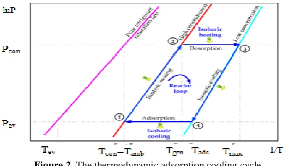
Figure 2. The thermodynamic adsorption cooling cycle.
Figure 1. The adsorption container is integrated with a flat plate solar collector and contains a porous adsorbent medium. The solid adsorbent has the affinity to adsorb the refrigerant vapour. Furthermore, the thermodynamic cycle of the adsorption refrigeration system is illustrated on Clapeyron diagram.
During the daytime period, the adsorption reactor is isolated from both the condenser and the evaporator by valves c and e and is completely saturated with the refrigerant. The pressure inside the reactor initially equals the evaporator pressure and its temperature is uniform and equals the ambient temperature , state 1 on Figure 2. The pressure and the temperature inside the bed increase when the reactor is heated by the solar radiation. This process continues till the pressure approaches at state 2.
At the end of this process valve c opens to allow the refrigerant vapour desorbed from the bed to flow towards the condenser while the adsorption reactor is still being heated by the solar radiation. The pressure inside the bed is fixed at the condenser pressure while the temperature continues to increase. Furthermore, the refrigerant content inside the reactor continues to decrease as more adsorbate is being freed from the reactor. The condensed refrigerant is then collected and stored in the refrigerant storage tank. Pressure swing adsorption (PSA) - is the removal of water vapour from compressed air flows. This process uses the dried air expanded to a lower pressure to purge the saturated bed for regeneration purposes. Temperature swing adsorption (TSA) - Regeneration of adsorbent in a TSA process is achieved by an increase in temperature. For any given partial pressure of the adsorbate in the gas phase, an increase in temperature leads to a decrease in the quantity adsorbed.
Figure 2. The cycle consists of four processes; pressurization preheating process at a constant concentration (isosteric heating process 1-2), desorption at constant pressure (isobaric heating process 2-3), depressurization at constant concentration (isosteric cooling process 3-4), and adsorption at constant pressure (isobaric cooling process 4-1).
Process I- Isosteric Heating Process 1-2
FIG. 3A HEATING AND PRESSURIZATION PROCESS [13] FIG. 3B HEATING AND PRESSURIZATION PROCESS[13]
Volume 2, Special Issue 1 MEPCON 2015
144 Process II- Isobaric Heating Process 2-3
Fig. 4A Cooling and Depressurisation Process[13] Fig. 4B Cooling and Depressurisation Process[13]
Adsorber releases heat while being closed. The adsorbent temperature continues decreasing which induces the pressure decrease from the condensation pressure down to the evaporation pressure.This stage is equivalent to expansion in compression cycle.
Process III- Isosteric Cooling Process 3-4
Figure 5A Cooling and Depressurisation Process[13] Figure 5B Cooling and Depressurisation Process[13]
Adsorber releases heat while being closed. The adsorbent temperature continues decreasing which induces the pressure decrease from the condensation pressure down to the evaporation pressure.This stage is equivalent to expansion in compression cycle.
Process IV- Isobaric Cooling Process 4-1
Volume 2, Special Issue 1 MEPCON 2015
145 It is the Cooling and Adsorption process. Adsorber continues releasing heal while being connected to the evaporator which now superimposes its pressure. The adsorbent temperature continues decreasing which induces adsorption of vapour. This adsorbed vapour is evaporated in the evaporator The evaporation heat is supplied by the heat source at low temperature .This period is equivalent to evaporation in compression cycle.
This cycle is intermittent because production of cooling energy is not continuous. It occurs only during part of cycle when there are two adsorbers in the unit, they can be operated separately and production of cooling energy can be quasi continuous.
V. SYSTEMLAYOUT
The experimental system has as main parameters mechanical simplicity, cost effectiveness and reliability rather than high levels of performance. Factors considered in the design and construction of the solar adsorption refrigeration system includes: solar irradiance, materials for construction, adsorption and desorption temperature, evaporation and condensation temperature. Figure 7 shows the cycle flow diagram for the machine. The machine will have to ensure safety in function and satisfy the accepted design standards. From the point of view of above stated objectives the solar powered Adsorption Refrigeration system with composite adsorbent is to be designed ,fabricated tested and compared with existing vapour compression system.
The components is to be selected/designed includes,
1. CHOICE OF THE WORKING PAIR (Composite adsorbent and refrigerant) 2. DESIGN OF THE COOLING CABINET
3. DESIGN OF THE EVAPORATOR 4. SOLAR COLLECTOR
5. CONDENSER
Economic comparison of solar powered Adsorption Refrigeration system with composite adsorbent and existing vapor compression system is to be carried out.
Figure.7 System Layout[10]
Figure 8: Valve arrangement
Volume 2, Special Issue 1 MEPCON 2015
146 Table 1:- Procedure for operating the experimental system:
Time Valve 1 Valve 2 Valve 4 Process
08.00 Close Close Close Heat adsorbent
11.00 Close Open Close Heat adsorbent Condensation
19.00-07.00 Open Close Open Evaporation: Cooling cycle
VI.CONCLUSION
This paper is the review on the fundamental understanding of adsorption refrigeration cycle and its application on refrigeration. As solar energy is used as an energy source, cooling systems are environment friendly and it compete the absorption and compression devices.
Solar thermal cooling technologies are being used for industrial and household cooling purposes. These cooling systems are more applicable in remote areas where conventional cooling is difficult and solar energy is readily available. These systems are also more suitable than conventional vapor compression refrigeration systems as working fluid used does not create pollution. Using stronger adsorbents and doing improvement in the heat transfer process, the adsorption system can be a great alternative to the future refrigeration need.
VII.REFERENCES
[1] M. Li, R.Z. Wang, Y.X. Xu, J.Y. Wu, A.O. Dieng; Experimental study on dynamic performance analysis of a flat plate solar solid-adsorption. refrigeration for ice maker; Renewable Energy 27, 211–221 (2002). [2] Louajari, M.; Mimet, A.; Ouammi, A. Study of the effect of finned tube adsorber on the performance of
solar driven adsorption cooling machine using activated carbon-ammonia pair.Appl. Energy 2011, 88, 690–698.
[3] Mannuel I,González, M.I.; Rodríguez, L.R. Solar powered adsorption refrigerator with CPC collection system: Collector design and experimental test. Energy Convers. Manag. 2007, 48, 2587–2594.
[4] Fadar, A.E.; Mimet, A.; Pérez-García, M. Modelling and performance study of a continuous adsorption refrigeration system driven by parabolic trough solar collector. Sol. Energy 2009, 83,850–861.
[5] X. Q. Zhai and R. Z. Wang, “Experimental investigation and performance analysis on a solar adsorption cooling system with/without heat storage,” Applied Energy, vol. 87, pp. 824-835, 2010.
[6] Grenier Ph., Guilleminot J.J., Meunier F. and Pons M. (1988). Solar powered solid adsorption cold store, A.S.M.E. Trans.-J. Solar Energy Eng.110, 192-197
[7] L.W. Wang, R.Z. Wang, J.Y. Wu and K. Wang; Compound adsorbent for adsorption ice maker on fishing boats; International journal of refrigeration 27, 401-408 (2004).
[8] Chang.M. Li, R.Z. Wang; Heat and mass transfer in a flat plate solar solid adsorption; Renewable Energy 28, 613–622 (2003).
[9] Fadar, A.E.; Mimet, A.; Pérez-García, M. Modelling and performance study of a continuous adsorption refrigeration system driven by parabolic trough solar collector. Sol. Energy 2009, 83, 850–861.
[10] BOUBAKRI, A., GUILLEMIONT, J. J., & MEUNIER, F. 2000. Adsorptive solar powered ice-maker: experiments and model. Solar Energy, 69(3), 249-263
[11] Wang L W ,Wang R Z,Oliveira R G.A review on adsorption working pairs for refrigeration .Renewable and Sustainable EnergyReviews2009;13:518–34.
[12]Hassan HZ, Mohamad A A, Al-Ansary H A. Development of a continuously operating solar driven adsorption cooling system:thermodynamic analysis and parametric study. Applied Thermal Engineering 2012 ;48:332–41.
![Fig. 6A: Cooling and Adsorption Process[13] Fig. 6B Cooling and Adsorption Process[13]](https://thumb-us.123doks.com/thumbv2/123dok_us/8874288.1815922/4.595.77.501.97.274/fig-cooling-adsorption-process-fig-cooling-adsorption-process.webp)
![Figure.7 System Layout[10]](https://thumb-us.123doks.com/thumbv2/123dok_us/8874288.1815922/5.595.171.454.344.742/figure-system-layout.webp)
