48
INTERNATIONAL JOURNAL OF ADVANCES IN ENGINEERING RESEARCH
DAMAGE DETECTION OF COST EFFECTIVE CFRP
COMPOSITE STRUCTURE USING FIBER OPTIC
SENSOR UNDER DYNAMIC LOAD
J. Jerold John Britto1, a, A. Vasanthanathan2, b, Dr. P. Nagaraj3, c
1Assistant Professor, Department of Mechanical Engg, Ramco Institute of Technology,Rajapalayam, India 2
Associate Professor, Department of Mechanical Engg, Mepco Schlenk Engineering College, Sivakasi, India
3
Sr. Professor & Head, Department of Mechanical Engg, Mepco Schlenk Engineering College, Sivakasi, India
ABSTRACT
Recent advances and cost reductions has simulated interest in fiber optical sensing. This technique helps to detect the damage in aircraft structure. Nowadays, most of the critical components of aircraft structure made up of composite structure. CFRP can significantly reduce the weight while increasing strength and durability. The weight reduction of the structure will increase the fuel efficiency. The composite structure subjected to static and dynamic loading during the running condition. This paper overviews the cost effective material selection (CFRP) and damage detection setup using fiber optic sensor under dynamic loading condition. The spectrum received from the damage detection setup is analysed to ensure the size, shape and damage condition. The intensity of spectrum depends on the damage size of the given component. The entire paper shows the damage detection under dynamic loading with various indenter for impact.
Keywords: Fibre optic sensor, Composite Laminate, CFRP, Impact.
INTRODUCTION
Carbon-fiber-reinforced polymers are composite materials. They have unique properties of relatively high strength at high temperatures coupled with low thermal expansion and low density [1] . The physical properties of composite materials are generally not isotropic in nature, but rather are typically anisotropic (different depending on the direction of the applied force or load). For instance, the stiffness of a composite panel will often depends upon the orientation of the applied forces and/or moments.
49
INTERNATIONAL JOURNAL OF ADVANCES IN ENGINEERING RESEARCH
a. Carbon Fibre
Carbon fibers are commercially available with a variety of tensile modulus values ranging from 207 MPa on the low side to 1035 MPa on the high side. In general, the low-modulus fibers have lower density, lower cost, higher tensile and compressive strengths, and higher tensile strains-to-failure than the high-modulus fibers.
Carbon fibers are their exceptionally high tensile strength–weight ratios as well as tensile modulus–weight ratios, very low coefficient of linear thermal expansion high fatigue strengths, and high thermal conductivity. Their high cost has so far excluded them from widespread commercial applications. They are used mostly in the aerospace industry, where weight saving is considered more critical than cost.
b Epoxy Resin & Hardener
Epoxy resins are the most used just after polyesters, their price being the only limit to their usage. They have better mechanical characteristics in tension, compression, impact and others when compared with polyester resins, and so they are preferred in the manufacturing of high performance parts like those used in aeronautics and others. Besides they present good heat resistance up to 150 to 1900 C, have good chemical resistance, [2] low retraction, good reinforcement wetting and an excellent adhesion to metallic materials. The hardener is used to cure the matrix materials in fibre as faster than usual curing time. From that we can get excellent adhesive bonding together and normally the proportion of hardener, epoxy resin is equal amount and equal to weight of fibre.
c. Fiber Optic Sensor
50
INTERNATIONAL JOURNAL OF ADVANCES IN ENGINEERING RESEARCH Fig. 1 Overview of Fiber Optic Sensors.
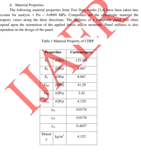
d. Material Properties
The following material properties from Test Data results [3,4] have been taken into account for analysis 1 Psi = 0.0069 MPa. Composites are the orthotropic material the property varies along the three directions. The stiffness of a composite panel will often depend upon the orientation of the applied forces and/or moments. Panel stiffness is also dependent on the design of the panel.
Properties Carbon/epoxy
Ea (GPa) 125.485
Eb (GPa) 8.067
Ec (GPa) 8.067
Gab (GPa) 41.29
Gbc (GPa) 2.42
Gca (GPa) 4.129
γba 0.0176
γcb 0.0176
γca 0.4657
Densit
y kg/m
3
51
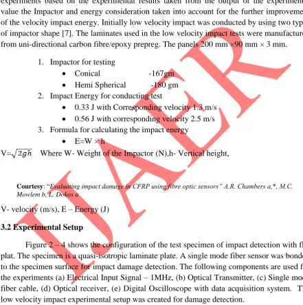
INTERNATIONAL JOURNAL OF ADVANCES IN ENGINEERING RESEARCH value the Impactor and energy consideration taken into account for the further improvement of the velocity impact energy. Initially low velocity impact was conducted by using two types of impactor shape [7]. The laminates used in the low velocity impact tests were manufactured from uni-directional carbon fibre/epoxy prepreg. The panels 200 mm ×90 mm × 3 mm.
1. Impactor for testing
Conical -167gm
Hemi Spherical -180 gm
2. Impact Energy for conducting test
0.33 J with Corresponding velocity 1.3 m/s
0.56 J with corresponding velocity 2.5 m/s 3. Formula for calculating the impact energy
E=W × h
V= Where W- Weight of the Impactor (N),h- Vertical height,
V- velocity (m/s), E – Energy (J)
3.2 Experimental Setup
Figure 2 – 4 shows the configuration of the test specimen of impact detection with flat plat. The specimen is a quasi-isotropic laminate plate. A single mode fiber sensor was bonded to the specimen surface for impact damage detection. The following components are used for the experiments (a) Electrical Input Signal – 1MHz, (b) Optical Transmitter, (c) Single mode fiber cable, (d) Optical receiver, (e) Digital Oscilloscope with data acquisition system. The low velocity impact experimental setup was created for damage detection.
Courtesy: “Evaluating impact damage in CFRP using fibre optic sensors” A.R. Chambers a,*, M.C.
52
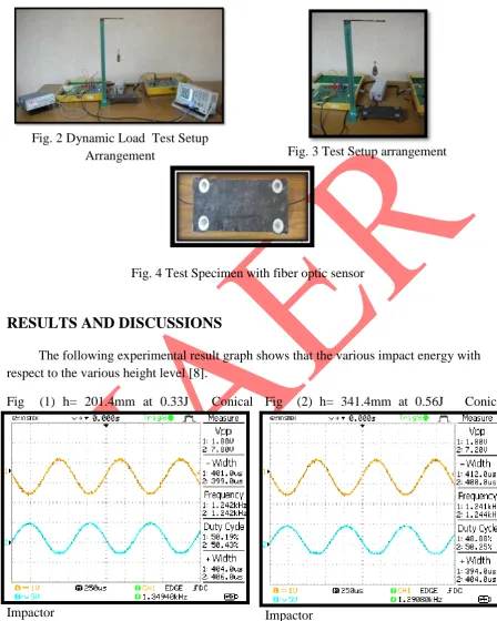
INTERNATIONAL JOURNAL OF ADVANCES IN ENGINEERING RESEARCH Fig. 2 Dynamic Load Test Setup
Arrangement Fig. 3 Test Setup arrangement
Fig. 4 Test Specimen with fiber optic sensor
RESULTS AND DISCUSSIONS
The following experimental result graph shows that the various impact energy with respect to the various height level [8].
Fig (1) h= 201.4mm at 0.33J Conical
Impactor
Fig (2) h= 341.4mm at 0.56J Conical
53
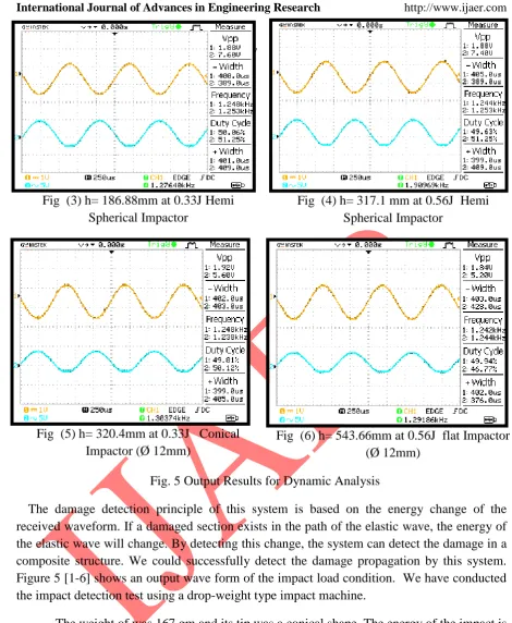
INTERNATIONAL JOURNAL OF ADVANCES IN ENGINEERING RESEARCH The damage detection principle of this system is based on the energy change of the received waveform. If a damaged section exists in the path of the elastic wave, the energy of the elastic wave will change. By detecting this change, the system can detect the damage in a composite structure. We could successfully detect the damage propagation by this system. Figure 5 [1-6] shows an output wave form of the impact load condition. We have conducted the impact detection test using a drop-weight type impact machine.
The weight of was 167 gm and its tip was a conical shape. The energy of the impact is 0.33 J at velocity 1.3 m/s. The figures 5 [1,3,5] shows the received waveform and the enlarged waveform of the elastic wave of fiber optic sensors under 0.33 J energy with height range of 201.6 mm, 186.88 mm and 320.4 mm. The figures 5 [2,4,6] shows the received waveform and the enlarged waveform of the elastic wave of fiber optic sensors under 0.56 J energy with height range of 341.4 mm, 317.1 mm and 543.6 mm. Based on this output wave the experimental setup detect the resulting damage. As the result of this study, it was revealed that two kind of detections, damage monitoring and impact detection, with the same system construction by the damage monitoring using single mode fiber sensor.
Fig (3) h= 186.88mm at 0.33J Hemi Spherical Impactor
Fig (4) h= 317.1 mm at 0.56J Hemi Spherical Impactor
Fig (5) h= 320.4mm at 0.33J Conical Impactor (Ø 12mm)
Fig (6) h= 543.66mm at 0.56J flat Impactor (Ø 12mm)
54
INTERNATIONAL JOURNAL OF ADVANCES IN ENGINEERING RESEARCH
CONCLUDING REMARKS
The following conclusions were drawn from the present experimental investigations:
1. Carbon fibre is suitable material for absorbing more energy during the impact loading condition. Based on the material property.
2. For the constant input voltage of 1.88v the output voltage varies with respect to the impact [Fig. 5 (1 – 6)] load energy of 0.56 J, the output voltage is 5.20v.
3. The shape of the impactor in this experimental work: conical, Hemi spherical and flat shape.
4. In this paper, the low velocity impact load is applied in between the range of 1.3 to 2.5 m/s.
5. The figure 5 [1 – 5] shows the output of the impact load on the composite plate and it shows the energyabsorption capability of carbon fiber material.
ACKNOWLEDGEMENT
All the praise goes to Almighty God for his source of all inspirations, for showering his divine and merciful blessings on us. We express our heartiest gratitude and the authors would like to thank The Principal/RAMCO Institute of Technology, Rajapalayam and The Principal/MEPCO SCHLENK Engineering College, Sivakasi for providing facilities to carry out this research work.
REFERENCES
[1] Deborah D.L. Chung, “Composite Materials Functions and modern Technologies” composite materials laboratory, University of Buffalo, New York, 2009..
[2] P. K. Mallick, “Fiber-Reinforced Composites: Materials, Manufacturing and Design” – Taylor & Francis Group, LLC.
[3] G. C. Sih and S. E. Hsu, “Advanced Composite Materials and Structures” – Publisher VNU Science Press BV.
[4] Kersey AD, Davis MA, Patrick HJ, LeBlanc M, Koo KP, Askins CG, PutnamMA, and Friebele EJ. Fiber grating sensors, Journal of Lightwave Technol., Vol.15, No. 8, pp 1442-1463, 1997.
55
INTERNATIONAL JOURNAL OF ADVANCES IN ENGINEERING RESEARCH [8] Taketa I, Amano M, Okabe Y, and Takeda N. Damage detection andsuppression system
of CFRP laminates with FBG sensor and SMA actuator.Trans. Mater. Res. Soc. Japan, Vol. 28, No. 3, pp 675-678, 2003.