Beno. 2015 ISSN: 2349 – 4891
60
Correlations of
BiomechanicalCharacteristics with Ball Speed in Penalty Corner Push-In
Analysis of Slot Loaded Patch Antenna for Miniaturization Using Slot and L Slits for Multiband
Wireless Applications
A. Beno
Associate Professor, ECE Department, Dr. Sivanthi Aditanar College of Engineering, Tiruchendur, Tamilnadu, India.
Received 27th November 2014, Accepted 21st January 2015
Abstract
This paper presents a microstrip patch antenna loaded with slots and slits to achieve miniaturization. The antenna is designed on FR4 substrate with a dimension of 27.1 mm 37.9 mm 2.4 mm. The antenna is introduced with six parallel slots along the length of the antenna and two L Slits along the edges achieving antenna miniaturization. A frequency miniaturization of 41.6 % with gain and radiation characteristics is achieved. The antenna exhibits good radiation characteristics with a peak gain of 6.49 dB with good directivity of 6.294 dB. The effect of increase in slot and slit length and width variation on miniaturization is presented with achieved S11 characteristics. The antenna operates as a
multiuband antenna covering major wireless applications like GPS, GSM, WLAN, Bluetooth and ISM.
Keywords: Microstrip, Miniaturization, Slot, Slits.
© Copy Right, IJRRAS, 2015. All Rights Reserved.
Introduction
The size reduction on every product has increased and created a influence on researchers to work on miniaturization. The influence on size reduction in communication equipments and products created high demand on antenna designs to reduce the effective size of the antenna. The concept of printed antenna has good attraction among researchers to utilize in the race of miniaturization using various techniques of miniaturization like using high dielectric substrate, folding of the patch, use of shorting post, using EBG, PBG materials, slots, slits and meta-materials [1-6]. To achieve miniaturization the simplest approach used is introducing slots and slits. The slot helps to create new resonant frequencies where the slits help to create meandering and helps to increase the electrical length of the antenna achieving miniaturization.
The slots are introduced on the radiating patch with various shapes and sized E, U, V, H-Shaped antennas which are presented by various researchers [7-9] and the effect of slits on meandering is also widely reported for miniaturization [10-11]. The effect of L shaped slots and strips on the radiating patch in various shapes and structures are given by researchers [12-14]. The effect of slot loaded antennas for dual and multiband applications has good attraction in various wireless applications [15-17]. A simple effort is taken to present the effect of slot on the radiating patch in miniaturization. Further the influence of L slits on the patch in the miniaturization through meandering with
Correspondence
A.Beno,
E-mail: [email protected], Ph. +9194434 53030
variable length is presented.
Antenna Miniaturization Using Slots
The antenna is designed with an operating frequency of 2.4 GHz on a FR4 dielectric having a permittivity of εr = 4.4. The patch antenna is placed above the ground on the dielectric substrate at a height of h = 2.4 mm. The basic antenna structure is introduced with a thin slot parallel to the electrical length with slot width, length given by SW = 1 mm and SL = 5 mm. The introduction of the slot in the patch creates the inductive effect inducing new resonant frequencies. The length of the slot is varied based on the ratio of operating wavelength as λ/4, λ/8, λ/16, λ/32, λ/64. The width of the slot is also changed to observe the variations on the antenna performance with changing widths as SW = 0.5 mm, SW = 1 mm, SW = 1.5 mm, SW = 2 mm and SW = 2.5 mm.
The variation in the length of the slot reduces the S11 characteristics in the lower band and the upper multiband. The entire operational characteristic of the antenna is changed with the introduction of the slot. When the current path is observed it clearly shows how the current with and without slot differs on the surface of the patch. This alteration in the surface current effectively alters the lower band frequency to further lower value achieving miniaturization. The reactive path of the antenna gets widely altered that indirectly affect the impedance of the antenna. Even then the new resonant frequencies generated make the antenna match itself to all the multibands. The VSWR against frequency plot clearly shows the matching in all the operating bands as the values stays below 1.5. (with 1:1.5). The antenna is designed with the introduction of slots parallel
ISSN: 2349 - 4891
International
Journal of Recent Research and Applied Studies
to the length of the antenna with variable length and width. The effect of the slot on the radiating patch is observed by introducing a single slot along the length of the radiating patch. The dimension of the slot is so chosen to match with the electrical length λ/4 of the patch antenna that helps to create inductive effect in the equivalent circuit influencing the resonant frequency of the antenna. The number of slots on the radiating patch is designed with six slots in the form of windows as given in the Figure 1. The window slots on patch resonate at a lower operating frequency of 1.58 GHz with S11-15.05 dB and a wide band response at the higher operating bands of 7.2 GHz to 8.5 GHz. The antenna achieves a frequency miniaturization of 34.16% from the fundamental operating frequency.
Figure 1. Radiating patch with window slots
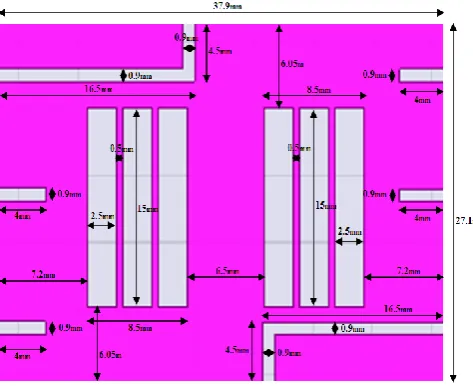
To achieve miniaturization narrow slits are used along the edges of the patch to facilitate meaeffect. The slits in the edges help the antenna to have frequency alterations in the higher bands, and help to isolate unwanted higher bands of frequency. The antenna is designed with two L slits one at the top left and the other at the bottom right edge of the patch with the dimensions as given in Figure 2.
Figure 2. Dimension of Antenna Structure
The length of the L slit is varied and analyzed for an optimum length of 15 mm whose electrical length is /16
with operating frequency of the patch. The length of the L slit is optimized by changing the length and width of the slot. The L slit in the top and bottom of the radiating structure reduces the effective length of the antenna and alters the electrical length of the physical structure. The electromagnetic coupling however affects the isolated structure and improves the radiation efficiency of the antenna. The slits in the edges create a meandering effect for the current to flow on the radiating patch. The parallel slots are created with a width of 2.5 mm and length of 15 mm. The S11against the frequency plot for the antenna with dual slits for miniaturization is shown in the Figure 3.
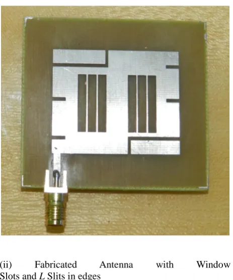
Figure 3. Radiating patch with Window Slots and L Slits in edges
The lower frequency shift to a lower frequency of 1.48 GHz with S11 value -10 dB and the other operating multiband covering the frequency bands 3.2 - 3.39 GHz, 4.1 - 4.34 GHz, 6.63 - 6.83 GHz, 8.43 - 9.45 GHz with good impedance matching in the operating bands. The VSWR against frequency for the designed antenna achieved less than 1.6 for the entire operating multiband as shown in Figure 4.
Figure 4. VSWR vs Operating Multiband Frequency
Results and Discussions
The simulated antenna was fabricated and an S11
62 Analyzer. The antenna achieved good matching between
the simulated and measured values. The S11 testing performed with network analyzer is given in the Figure 5 (i) and the fabricated antenna structure with L slits having length 15 mm and 31.2 mm is shown in the Figure 5 (ii).
Figure 5. (i)Testing with Network Analyzer
(ii) Fabricated Antenna with Window Slots and L Slits in edges
The comparison of simulated results with measured values of S11characteristics is given in Figure 6.
Figure 6. Simulated and Measured S11Characteristics
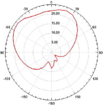
The antenna exhibits good radiation characteristics as required for commercial wireless communications. The antenna operates with a total gain of 6.49 dB having a directivity of 6.29 dB as given in Figure 7 (i) and 7 (ii).
Figure 7. (i) Directivity at 8.91GHz
The fabricated antenna is tested for radiation characteristics in the anechoic chamber as shown in Figure 8.
Figure 8. Antenna Testing with Anechoic Chamber
The simulated antenna radiation pattern for the
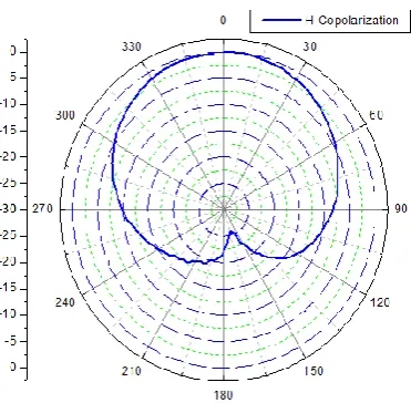
E- field and H-field is given in the Figure 9 (i) and 9 (ii). The radiation pattern testing is performed in the anechoic chamber for E-field co-polarization and cross polarization as shown in Figure 10 (i) and 10 (ii).
Figure 9. (i) Simulated E-field Radiation Pattern
(ii) Simulated H-field Radiation Pattern
Figure 10. (i) Measured E-field Co-polarization
(ii) Measured E-field Cross Polarization
64 Figure 11. (i) Measured H-field Co-polarization
(ii) Measured H-field Cross Polarization
Conclusion
In this paper a novel design of parallel slotted dual L slit microstrip patch antenna is presented. The design helps to give an insight into the concept of achieving miniaturization using slots. The work presents the effect of a slot on radiating patch to the introduction of the dual L slits in the structure and its influence on S11 characteristics. The antenna operated in the fundamental frequency of 2.4 GHz is made to operate in multiband having the lower band starting at 1.4 GHz achieving a frequency miniaturization of 41.6%. The antenna operate as multiband covering the frequency band 1.3 - 1.6 GHz (GPS), 2.4 - 2.75 GHz (WLAN), 2.9 - 3.1 GHz (S-Band), 4.4 - 4.6 GHz (IMT), 5.4 - 5.7 GHz (Wi-Max) and 7.55 - 10 GHz (X-Band). The antenna achieved good radiation characteristics with a peak gain of 6.49 dB and above 2 dB in all the operating bands.
Acknowledgment
The authors sincerely thank the Head of the Department of Electronics and Communication and Technical team of Microwave division of CUSAT, Cochin for providing the testing facilities.
References
1. David M.Pozar and Daniel H.Schoubert, “Microstrip Antennas, The Analysis and Design of Microstrip Antennas and Arrays”, John Wiley & Sons, 15 May 1995.
2. R. Garg, P. Bhartia, I. Bahl, and A. Ittipiboon, “Microstrip Antenna Design Handbook”, Artech House, London, 2001.
3. R. Chair, C.-L. Mak, K.-F. Lee, K.-M. Luk, and A. A. Kishk, “Miniature Wide-and Half U-Slot and Half E-Shaped Patch Antennas”, IEEE Transactions on Antennas and Propagation, Vol. 53, No. 8, pp. 2645–2652, 1983.
4. C. Y. Chiu, C. H. Chan, and K. M. Luk, “Study of a Small Wide-Band Patch Antenna With Double Shorting Walls”, IEEE Antennas Wireless Propagation Letters, Vol. 3, pp. 230–231, 2004. 5. A. K. Shackelford, K. F. Lee, K. M. Luk, and R.
Chair, “U-Slot Patch Antenna with Shorting Pin”, Electronics Letters,Vol. 37, No. 12, pp. 729–730, 2001.
6. K. L. Lau, K. C. Kong, and K. M. Luk, “A Miniature Folded Shorted Patch Antenna for Dual-Band Operation,” IEEE Transactions on Antennas and Propagation, Vol. 55, No. 8, 2007.
7. M. T. Islam, M. N. Shakib and N. Misran, “Broadband E-H Shaped Microstrip Patch Antenna For Wireless Systems”, Progress In Electromagnetics Research, PIER 98, 163-173, 2009.
8. Wang Ren, Zhiguo Shi,Yu Li,and Kangsheng Chen, “Compact Dual-Band T-Slot Antenna for 2.4/5GHz Wireless Applications”, Page No.2493-2497, IEEE 2006.
9. G.F.Khodaei, J.Nourinia, and C.Ghobadi, “A Practical Miniaturized U-Slot Patch Antenna with Enhanced Bandwidth”, Progress in Electromagnetic Research B, Vol.3, 47-62, 2008.
10. Prabhakar H.V., U.K. Kummuri, R.M. Yadahalli and V. Munnappa, “Effect of Various Meandering Slots in Rectangular Microstrip Antenna Ground Plane For Compact Broadband Operation”, Electronics Letters, Vol. 43 No. 16, 2nd August 2007.
11. A. Kaya, “Meandered Slot And Slit Loaded Compact Microstrip Antenna With Integrated Impedance Tuning Network”, Progress In Electromagnetics Research B, Vol. 1, 219–235, 2008.
13. Lin Peng, Cheng-Li Ruan, “A Microstrip Fed Patch Antenna with Two Parasitic
Invert L Stubs for Dual-Band WLAN
Applications”, Wireless Personnel Communication, Nov 2009.
14. C.-J. Wang, Y.-J. Lee, and K.-C. Lee, “A Dual-Band CPW-Fed L-Slot Antenna With Both Linear And Circular Polarizations, Progress In Electromagnetics Research C, Vol. 21, 229-241, 2011.
15. Y.-C. Lee and J.-S. Sun, “Compact Printed Slot Antennas for Wireless Dual and Multi-Band Operations”, Progress In Electromagnetics Research, PIER 88, 289–305, 2008.
16. Heng-Tung Hsu, Fang-Yao Kuo, and Ping-Hung
Lu, “Design Of Wi-Fi/Wi-MAX Dual-Band
E-Shaped Patch Antennas Through Cavity Model Approach”, Microwave And Optical Technology Letters, Vol. 52, No. 2, pp-471-474, February 2010.
17. Mudar A. Al-Joumayly, Suzette M. Aguilar, Nader Behdad, and Susan C. Hagness, “Dual-Band Miniaturized Patch Antennas for Microwave Breast Imaging”, IEEE Antennas And Wireless Propagation Letters, Vol. 9, 2010.