Miniature Triangular Circulator with Coplanar
Waveguide Structure
Telecommunications and Digital Signal Processing Laboratory, University of Djellali Liabest, Sidi Bel Abbes, Algeria Email: [email protected], [email protected]
Abstract—A different form of coplanar triangular circulator
structures is proposed in this work. The HFSS is used to simulate the circulator and to check the non-reciprocal characteristics at operating frequency. In this analysis, an insertion loss of -0.21 dB and an non-reciprocity of -33 dB appeared at around 13.5 GHz; these results show good circulation performances of the device. The miniaturization of device need to have a small size which it is a principal advantage of a coplanar triangular circulator.
Index Terms—circulator, S-parameters, ferrite, non
reciprocity, triangular stricture
I. INTRODUCTION
In recent years, the Democratization of telecommunications systems, for reasons of compactness and cost, has led a race for miniaturization of nonreciprocal devices using a magnetic materials subjected to a static magnetic field such as circulators. These passive components include the ability to differentiate and select the waves transmitted and received by the telecommunications systems. A many different topologies can be designed of circulators, all different from each other, but their common property is the nonreciprocity of the device.
The stripline Y-junction circulator has been studied by Bosma in 1962 [1]. This study is allowed to establish the circulation conditions and from there on, to deduce the essential physical parameters in the design of stripline circulators.
Many researchers have improved the circulator performances using the microstrip structure [2]. The CPW line was introduced in 1969 by Wen [3]. In 1971; Ogasawara [4] has showed and has confirmed that the Y-junction circulators with CPW successfully operated at certain frequencies. This work is devoted to the study of the three port ferrite circulator using CPW technology. In particular cases we will study a different type of circulator that uses a triangular central pattern. The triangular structure has been proposed and studied by J. Helszajn [5], [6] using a microstrip topology. Certain
Manuscript received September 11, 2013; revised February 15, 2014.
advantages in terms of performance relative to the circular structure have been demonstrated. Recently, Zahwe was suggested this triangular structure in topology coplanar [7]. In this work, the main approach will be developed in order to improve the performance of the coplanar triangulaire circulator and compare our results with that of Zahwe [7].
II. THEORY
The conception of a coplanar triangular circulator is based on the parametric study presented in [1], [5]. The Y-junction stripline circulator proposed by Bosma [1] is the most used of such passive microwave components.
From the theoretical results obtained by J. Helszajn [6]:
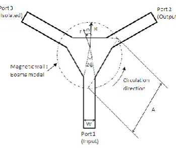
√ (1) r either represents the inscribed radius defined by the triangular resonator, and A is the length of the side of the inner triangular conductor, shown in Fig. 1.
Or the actual radius of the ferrite disk:
(2)
We can calculate the value of the triangle side A from this equation [6]:
⁄ (3)
k is the wave number in the medium and is defined by:
√
and(4)
where is the relative dielectric constant, is the effective permeability of the ferrite calculated from the model of Polder. K and µ are the elements of the tensor Polder ferrite.
From measurements of the resonant frequency for the first mode, authors in [6] found that the edges of the resonator are not really perfect magnetic walls. They defined the effective value of the triangle side Aeff as
follows [7]:
(5)
where h is the thickness of the ferrite layer.
Figure 1. Configuration of the central conductor.
It is possible to determine the stripline conductor’s width W depending on the stripline width angle ψ and the radius of the ferrite disks lines R as follows [1]:
, √ ⁄
√ ⁄𝜀
(6)
The magnetic material used in [1] is the ferrite which it is placed in the center for device. This magnetic material gives the circulator its non-reciprocity. The ferrite is polarized along the axis of the cylinder and saturated. The ferrite is polarized along the axis of the cylinder and saturated using an internal static magnetic field given by the following expressions:
√√ (7)
where λ is the free space wavelength, w is the radius of
the central conductor, Ms is the saturation magnetisation
and H0 is the external static field is defined by:
(8)
With
,
respectively represent the gyromagnetic factor, the angular frequency.III. COPLANAR TRIANGULAR CIRCULATOR
The simply structure on study is shown in Fig. 1, which has dimensions of 331 mm3. The central part of our device has a triangular configuration. The metallization (ground plane (GND) of 1 μm thickness is made of copper. A ground plane (GND) in the form of a triangular thin film is placed at the center of the junction on the ferrite (see Fig. 1.b). it provides the signal transition from access lines to central conductive portion triangular lines (horizontal) [8].
Figure 2. Structure of a CPW triangular circulator. (a) top view, (b) cross-section of the CPW structure.
The integration of magnetic material is essential for producing the non-reciprocal properties of the ciculator. The thickness of the ferrite layer is h=1 mm. It is defined by the following features: a relative permittivity εr=15.3,
a saturation magnetization 4Ms=1780 Gauss,a dielectric
loss tangent tanE=10 -4
(measured value in about 9.4 GHz), and a ferromagnetic resonance (FMR) linewidth H = 100 Oe and . An internal magnetic field polarization Hi=350.57KA/m was applied in a direction perpendicular to the ferrite layer (see (7)).The conductor line and GND planes was made of copper with a relative permeability µ= 0.999991 and a conductivity σ = 58.106 S / m.
Table I above shows a comparison of the performance of the circulator having conductors with thicknesses of 1 and 4 µm of copper or gold. These results obtained did not show a remarkable difference in performance of coplanar circulator. It was found that the conductive material either gold or copper with very little influence on circulator performance when the thickness of ferrite is important.
TABLE I. PERFORMANCE OF THE CIRCULATOR ACCORDING TO THE
CONDUCTIVE MATERIAL (COPPER / GOLD) AND ITS THICKNESS
Transmission (dB)
Isolation (dB)
Reflexion (dB)
Copper
1µm -0.22 -50.17 -29.27
4µm -0.21 -26.32 -28.80
Gold
1µm -0.20 -32.21 -26.97
IV. PARAMETRIC STUDIES OF THE BEHAVIOR OF A COPLANAR TRIANGULAR CIRCULATOR
The commercial software ANSOFT-HFSS was employed. We studied the effects of several parameters on the performance of the circulator. From the parameter studies, the dimensions of our circulator are obtained as follows: A = 3 mm (the side of the inner central triangle), W = 0, 14 mm (the width of signal line), G1 = 0,08 mm (a
signal Line-to-GND spacing), G2 = 0,90 mm (spacing
between GND plane and the signal line). The resulting characteristic impedance is equal to 48.
In addition, the electromagnetic configuration shows the electric field distribution of the coplanar triangular circulator (the field displacement phenomenon) (see Fig. 3). The electromagnetic configuration of Fig. 3 shows the circulation phenomenon of the device. The electromagnetic field has a coplanar configuration on access lines level.
Figure 3. Circulation phenomenon: Signal transmitted from port 1 to port 2, port 3 is isolated.
The results of the simulation parameters of the circulator are illustrated in Fig. 2.
The non-reciprocal transmission characteristics represented by | | , is observed at 13.55 GHz. The signal propagates from port 1 to port 2 with insertion losses | | , in the direction of the port 3, the signal is blocked with an isolation rate | | of the order of 32.53dB and the return loss at the port 1 is
| | .
Figure 4. Evolution of S-parameters of a triangular coplanar circulator.
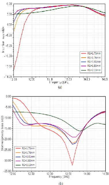
A. Effect of Radius of Triangular GND (RG) on the S-parameters
The effect of the RG parameter (radius of triangular GND) on transmission characteristic, such as insertion loss S21 and non-reciprocity S12 is investigated. This
parameter was calculated from (5) that shows the geometric relationship between the side and the radius of the circumcircle of a triangle (see Fig. 1).
The results presented in the figure below shows that the gap RG varies from 1.73 mm to 2.13 mm. The Insertion losses have the same level lower at 0.5 dB. The variation of this parameter directly affects the reciprocity loss. The circulator achieves the best non-reciprocity loss value when RG=1.73 mm.
Figure 5. Effect of the RG on the transmission characteristics, (a) Insertion loss, (b) Nonreciprocity loss.
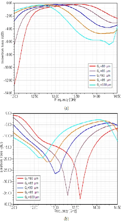
B. Effect of the G1 and G2
The influence of the G1 (a signal Line-to-GND spacing)
and the S (spacing between GND plane and the signal line) are studied to estimate their influence on the S-parameters and assess their impact on device performance. We are executed at several simulations to study the behavior of the circulator by Ansoft HFSS.
The parameters G1 varies from 80 to 100 µm which
impedance of access remains close to 50 Ω. From the Fig. 6, we can be clearly seen that the S-parameters vary on a regular way with the G1 parameter; when the G1 increases;
the isolation loss with a negative sign also increases. The frequency was infulenced by the variation of G1, the
circulation frequency is 12.6 GHz for G1=100 µm and it becomes 13.5 GHz for G1=80µmm. The best
performance is obtained at the G1 = 80 µm with the
insertion loss of 0.21 dB and isolation of 38.25dB. This value was selected of our circulator.
Figure 6. Dependence of S-parameters on the G1 (a signal
line-to-GND spacing). (a) Insertion loss, (b) Isolation loss
Another set of simulation is done to quantify the effect of G2 (spacing between GND plane and the signal line)
on the S-parameters (show Fig. 7).
The G2 parameter varies from 300 and 900 µm. The
S-parameters (S12 and S11) are sensitive to variation of the
G2 parameter. The non-reciprocity gets the best
performance at G2 = 900 µm for a | | (see
Fig. 7.a)and the best return loss for a | | 6
(see Fig. 7.b). The degradation of G2 was reached to the
disappearance of the non-reciprocal effect of component.
Figure 7. Dependence of S-parameters on the G2 (spacing between
GND plane and the signal line). (a) Nonreciprocity loss, (b) return loss.
V. CONCLUSION
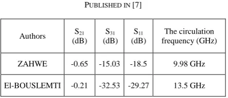
TABLE II. COMPARISON BETWEEN OUR RESULTS AND THOSE
PUBLISHED IN [7]
Authors (dB) S21 (dB) S31 (dB) S11 frequency (GHz) The circulation
ZAHWE -0.65 -15.03 -18.5 9.98 GHz
El-BOUSLEMTI -0.21 -32.53 -29.27 13.5 GHz
Reading these results, it appears that the performance of our circulator was highly elevated.
REFERENCES
[1] H. Bosma, “On the principle of stripline circulation,” in Proc. the Institution of Electrical Engineers January, 1962, pp. 137–146. [2] B. Peng, W. Zhang, Y. Sun, J. Lin, and W. Zhang, “Design of
microstrip Y-junction circulator based on ferrite thin films,” in
Proc. Microwave Conference (CJMW), China-Japan Joint,2011. [3] C. P. Wen, “Coplanar waveguide: A surface strip transmission
line suitable for a nonreciprocal gyromagnetic device applications,” in Proc. G-MTT International Microwave Symposium, Dallas, USA, 1969, pp. 110–115.
[4] N. Ogasawara and M. Kaji, “Coplanar-guide and slot-guide junction circulator,” Electric Lett., vol. 7, no. 9, pp. 220–221, 1971.
[5] J. Helszain, D. S. James, and W. Terence Nisbet, “Circulators using planar triangular resonators,” IEEE Transacations on Microwave Theory and Techniques, vol. MTT-27, no. 2, February 1979.
[6] J. Helszain, “Fabrication of very weakly and weakly magnetized microstrip circulators,” IEEE Transacations on Microwave Theory and Techniques, vol. 46, no. 5, May 1998.
[7] J. Helszain, D. S. James, and W. Terence Nisbet, “Circulators using planar triangular resonators,” IEEE Transacations on Microwave Theory and Techniques, vol. MTT-27, no. 2, pp. 188-193, February 1979.
[8] E. Benevent, T. Rouiller, B. Sauviac, V. Larrey, D. Vincent, and A. Madelaine, “Stripline Y-junction circulator using barium hexagonal ferrite thin films,” in Proc. IEEE International Symposium on Industrial Electronics, Ajaccio, France, 2004, pp. 15-18.
Rahmouna El-Bouslemti was born in Algeria in June 1980.Shereceived his engineering degree in electronics (communications) from Djillali Liabes University in Sidi Bel-Abbes, Algeria in 2004.
S h e g o t a M a g i s t e r d e g r e e i n o p t i c a l communication and microwave from Djillali Liabes University, Algeria in 2007. Currently she is a teacher at university. She is preparing her Doctoral thesis. His research focuses on the development and miniaturization of microwave components, microwave and electromagnetic propagation.