Vol.6 (2016) No. 5
ISSN: 2088-5334
Hardware-in-Loop-Simulator for InnoSAT Attitude Control System
S. M. Sharun
#, M. Y. Mashor
*, F. Hashim
#, F. A. Bakri
##
Faculty of Innovative Design and Technology, Universiti Sultan Zainal Abidin, Gong Badak Campus, Terengganu, 21300, Malaysia E-mail: [email protected]
* School of Mechatronic Engineering, Universiti Malaysia Perlis, Ulu Pauh Campus, Ulu Pauh, Perlis, 02600, Malaysia E-mail: [email protected], [email protected]
* Faculty of Electrical Engineering, Universiti Teknologi MARA, Jalan Maranek, Kota Samarahan, Sarawak, 94300, Malaysia E-mail: [email protected]
Abstract— After launching, the initial condition of satellite is unknown and tends to be in a tumbling state. At this moment, the satellite needs to reduce the tumbling rate so that the satellite can enter a stable and unruffled state. The satellite also must maintain a certain attitude while orbiting in order to allow precise pointing of the antenna toward the earth. In this study, a hardware-in-loop-simulator was devised for the purpose of improving the design and verifying attitude control concepts for Innovative Satellite (InnoSAT) system. A new software architecture and algorithm was developed based on the controller, InnoSAT plant, actuator and sensor. Firstly, the controller, actuator and sensor was modelled in the MATLAB program together with InnoSAT plant. The actuator and sensor were assumed to be ideal. However, some properties of the actuator and sensor were simulated in the software simulator. If the software simulation performed satisfactorily, the control algorithm will be embedded into Rabbit Micro Controller (RCM4100) using Dynamic C language. This is the part where the hardware simulation is developed which is creating hardware-in-loop-simulation technique for verification of InnoSAT Attitude Control System (ACS) performance. The satellite simulator was tested using simulated data in order to observe the performances of the controller in real time simulation. The results show that the InnoSAT ACS simulator can produce as good result as a MATLAB simulation for the InnoSAT plants. From the results, it is adequate to verify that the developed protocol working satisfyingly and seems to be possible to be implemented on the actual flight.
Keywords— innovative satellite, attitude control system, rabbit micro controller, hardware-in-loop-simulation.
I. INTRODUCTION
Nowadays simulations are widely used in the science and technology research, because they provide the ability to complete virtual experiments approximately same as the real ones. It also requires low cost in building simulation systems whose environment can be reconstructed many times. The satellite attitude control simulator (ACS) is a test bench used to evaluate the performance and robustness of the attitude control design. Typically, different simulators are developed throughout the satellite development to support validation and verification activities. There are many advancements that have been made in this research field and many constraints have been dealt with. Even so, there is still room for improvement in the development of the satellite attitude control systems. Therefore, many universities and research centres have developed similar facilities in the study of satellite control. For example, the development of 3-axis motion simulator [1], [2], autonomous docking [3]-[7],
real-time hardware simulator [8]-[11] and spacecraft attitude dynamics simulator [12], [13].
hardware and software and making them work together in pace [15], [16].
II. METHODOLOGY
A. Hardware-in-Loop-Simulation Technique
Hardware-in-loop-simulation (HILS) is a real-time test technology which is used to test one or a set of remaining system components in a comprehensive, cost effective and repeatable manner. HILS is often used in the development and testing of embedded systems, when those systems cannot be tested easily thoroughly and repeatedly in their operational environments. Instead of being connected to the real equipment, it is actually connected to the real time simulation. HILS test concept can be applied to a wide variety of systems, from relatively simple devices such as a room temperature controller to complex systems like an aircraft flight control system. HILS has historically been used in the development and testing of complex and costly systems such as military tactical missiles, aircraft flight control systems, satellite control systems and nuclear reactor controllers [15].
In this research, a Rabbit Micro Controller (RCM4100) was used to implement an attitude control algorithm for InnoSAT system as a hardware simulator. A computer on the other hand, simulated the attitude dynamics of the satellite as a software simulator. The software simulator integrates the dynamics equations and sends the output responses of the satellite to the RCM4100 using serial communication. The output responses were used in the control algorithm to generate necessary control signals. Closed loop simulations can be made to work in real time to simulate the dynamic behaviour of the satellite system with the ACS to control its attitude. It is important that the ANC controller can work properly with the RCM4100 microcontroller board because it will be used for attitude control system of the InnoSAT plant.
Fig. 1 shows a general block diagram of HILS technique for InnoSAT plant that consists of sensor and actuator. A software simulator represents the satellite dynamics model, incorporating all the operating conditions of the satellite in orbit. Fig. 2 shows the connection of satellite simulator for InnoSAT ACS system.
Fig. 1 General block diagram of HILS technique for InnoSAT plant
B. Requirements
The RCM4100 series is the first of the next-generation core modules that takes advantage of the new Rabbit® 4000 features such as hardware DMA, clock speeds of up to 60 MHz, I/O lines shared with up to six serial ports and four levels of alternate pin functions. It has a generous memory size (512K flash memory, 256K data SRAM) that allows large programs with tens of thousands of lines of code and substantial data to be stored. In this HILS technique, there is a need of a standard Personal Computer (PC) to be used as a satellite model that represents the InnoSAT dynamic behaviour. This PC will act as a software simulator in order to perform the function of InnoSAT attitude control simulator. Communication between the computer and RCM4100 takes place in the beginning of every sample period (1 s) of the system. Thus, both the computer and the RCM4100 must be able to complete necessary computations in less than this time. Since the given sample time is quite large, both the RCM4100 and computer fulfil this requirement. They rely on serial communication for transmission of bytes, representing state variables and actuator signals.
Fig. 2 Satellite simulator connection for InnoSAT ACS system
C. RCM4100 and Computer Interface
header using character ‘R’ for roll data, ‘P’ for pitch data and ‘Y’ for yaw data and character ‘#’ is used for the footer. This procedure is used in order to make sure the RCM4100 and computer receive the correct data to be processed.
Fig. 3 Match-pattern procedure for HILS technique
III.RESULTS AND DISCUSSION
In this section, the output response of HILS and MATLAB simulation for three axes InnoSAT plant are presented. The InnoSAT plants with small Euler angle can be described by a difference equation of discrete form:
where K_p (t) is a varying gain, u_s's(t) are the controller output and u_d's(t) are the constant disturbance torque. Meanwhile, x(t),y(t)and z(t) are the outputs from InnoSAT plant for Roll, Pitch and Yaw axes.
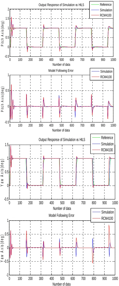
The InnoSAT plants has been tested in condition of unity gain by using step input as shown in Fig. 4. In order to evaluate the performance of the controller and to test the capability of the controller to adapt sudden changes due to the satellite rotation, the InnoSAT plant was excited by a square wave input reference with the amplitude of one and a frequency corresponding to 1000 number of data as shown in Fig. 5.
Fig. 4 shows the zoom out output response of MATLAB simulation and HILS for step input, while Fig. 5 shows the output response and model following error for square wave input. Based on the two figures, it can be clearly seen that the output response of HILS for all axes has almost the same response as MATLAB simulation. It is quite difficult to see the difference in the output response between MATLAB simulation and HILS. Therefore, the performance analyses of the output responses have been done by plotting the residual error and calculating the Mean Square Error (MSE) value. Residual errors are plotted in order to see whether the MSE calculations have misleading values. Based on the value of the MSE as shown in Table I and Table II and residual error plotting in Fig. 5, it is clearly proved that there is a close match between the two simulations. The
differential value of MSE for the both simulations is small thus proving satisfactory performance of the ACS operating in real time environment for InnoSAT plant.
0 10 20 30 40 50 60 70 80 90 100 -0.5
0 0.5 1 1.5
Output Response of Simulation vs HILS
Number of data
R o ll A x is (d e g ) Reference Simulation RCM4100
0 10 20 30 40 50 60 70 80 90 100 -1
0 1 2
Number of data
P it c h A x is (d e g )
0 10 20 30 40 50 60 70 80 90 100 -0.5
0 0.5 1 1.5
Number of data
Y a w A x is (d e g )
Fig. 4 Output response of simulation and HILS with step input
TABLEI
MSEOFSIMULATIONANDHILSWITHSTEPINPUT
Controllers Mean Square Error (MSE)
Roll Axis Pitch Axis Yaw Axis
Simulation
(MATLAB) 0.0099 0.0068 0.1099
HILS
(RCM4100) 0.0095 0.0066 0.0955
0 100 200 300 400 500 600 700 800 900 1000
-0.5 0 0.5 1 1.5
Output Response of Simulation vs HILS
Number of data
R o ll A x is (d e g )
0 100 200 300 400 500 600 700 800 900 1000
-1 -0.5 0 0.5
Model Following Error
Number of data
0 100 200 300 400 500 600 700 800 900 1000 -0.5 0 0.5 1 1.5 2
Output Response of Simulation vs HILS
Number of data
P it c h A x is (d e g )
0 100 200 300 400 500 600 700 800 900 1000
-0.5 0 0.5 1
Model Following Error
Number of data
P it c h A x is (d e g ) Reference Simulation RCM4100 Simulation RCM4100
0 100 200 300 400 500 600 700 800 900 1000
-0.5 0 0.5 1 1.5
Output Response of Simulation vs HILS
Number of data
Y a w A x is (d e g )
0 100 200 300 400 500 600 700 800 900 1000
-1 -0.5 0 0.5 1
Model Following Error
Number of data
Y a w A x is (d e g ) Reference Simulation RCM4100 Simulation RCM4100
Fig. 5 Output response and model following error of simulation and HILS with square wave input
TABLE III
MSE OF SIMULATION AND HILS WITH SQUARE WAVE INPUT
Controllers Mean Square Error (MSE)
Roll Axis Pitch Axis Yaw Axis
Simulation
(MATLAB) 0.0500 0.0189 0.1153
HILS
(RCM4100) 0.0480 0.0196 0.1057
IV.CONCLUSIONS
The ACS control algorithm in RCM4100 and the dynamics model of InnoSAT plant in PC have been tested
using real-time hardware-in-loop-simulation (HILS)
technique. The performance of each part of the hardware simulator were tested and modified repeatedly until the results were similar to the MATLAB simulation results. Finally, it serves (after adaptation) as a hardware-in-the-loop simulator and test platform for full system verification and on-orbit operations support tool. The results show that the InnoSAT ACS HIL simulator can produce as good result as MATLAB simulation of InnoSAT plants. The calculated MSE values also show that there are a close match between HILS and MATLAB simulation, where the MSEs different value are small. From both results, it is enough to verify that the developed protocol working satisfyingly and seems to be possible to be implemented on the actual flight. Now, the controller can be ‘plug and play’ in the real InnoSAT plant.
ACKNOWLEDGMENT
The authors would like to thank Astronautic Technology (M) Sdn. Bhd., Malaysia who provided information and advice for this work. We also gratefully acknowledge and thank the Universiti Sultan Zainal Abidin (UniSZA) for providing the financial support for this research project under grant RAGS.
REFERENCES
[1] X. Yue, M. Vilathgamuwa, K. Tseng and N. Nagarajan, “Modeling and robust adaptive control of a 3-axis motion simulator,” in Proc. 36th IEEE IAS'01, 2001, p. 553-560.
[2] D. M. Vilathgamuwa, X. Yue and K. Tseng, “Development and control of a 3-axis motion simulator for satellite ADCS hardware-in-the-loop simulation,” in Proc. 30th IEEE IECON'04, 2004, p. 524-529.
[3] S. Nolet, E. Kong and D. W. Miller, “Autonomous docking algorithm development and experimentation using the SPHERES testbed,” in Proc. SPIE Defense and Security, 2004, p. 1-15. [4] S. Nolet, E. Kong and D. W. Miller, “Design of an algorithm for
autonomous docking with a freely tumbling target,” in Proc. SPIE Defense and Security, 2005, p. 123-134.
[5] M. Romano, D. A. Friedman and T. J. Shay, “Laboratory experimentation of autonomous spacecraft approach and docking to a collaborative target,” Journal of Spacecraft and Rockets, vol. 44, pp. 164-173, Jan. 2007.
[6] T. Boge, T. Wimmer, O. Ma and M. Zebenay, “EPOS-A Robotics-based hardware-in-the-loop simulator for simulating satellite RvD operations,” in Proc. 10th iSAIRAS'10, 2010, p. 1-8.
[7] T. Boge and O. Ma, “Using advanced industrial robotics for spacecraft rendezvous and docking simulation,” in Proc. IEEE ICRA'11, 2011, p. 1-4.
[8] A. Ptak and K. Foundy, “Real-time spacecraft simulation and hardware-in-the-loop testing,” in Proc. 4th IEEE RTAS'98, 1998, p. 230-236.
[9] S. Zhaowei, X. Guodong, L. Xiaohui and C. Xibin, “The integrated system for design, analysis, system simulation and evaluation of the small satellite,” Advances in Engineering Software, vol. 31, pp. 437-443, Jul. 2000.
[10] R. Finnset, S. K. Rao and J. Antonsen, “Real time hardware-in-loop simulation of ESMO satellite attitude control system,” Modeling, Identification and Control, vol. 27, pp. 125, 2006.
[11] Q. Wang, T. Zhang and J. Song, “Study on the control system of a hardware-in-loop micro-satellite simulator,” in Proc. IEEE ROBIO'09, 2009, p. 2427-2432.
[13] J. W. Chia, K. S. Low and Y. T. Xing, "A novel simulator for measuring the performance of nanosatellite's attitude control system," in Proc. IEEE Aerospace Conference, 2016, p. 1-7. [14] W. Sun, X. Cai and Q. Meng, “Testing flight software on the ground:
Introducing the hardware-in-the-loop simulation method to the alpha magnetic spectrometer on the international space station,” Nuclear Instruments and Methods in Physics Research Section A: Accelerators, Spectrometers, Detectors and Associated Equipment, vol. 815, pp. 83-90, Apr. 2016.
[15] F. Bayat, “Conceptual design of a low-cost real-time hardware-in-the-loop simulator for satellite attitude control system,” Turkish Journal of Electrical Engineering and Computer Science, vol. 23, pp. 789-803, 2015.