Available Online at www.ijpret.com 719
INTERNATIONAL JOURNAL OF PURE AND
APPLIED RESEARCH IN ENGINEERING AND
TECHNOLOGY
A PATH FOR HORIZING YOUR INNOVATIVE WORK
SIMULATION OF UPFC FOR SINGLE PHASE TRANSMISSION LINE SYSTEM
MS. PRIYA. P. GAIKWAD, MR. PRASHANT A. MESHRAM, MS.TRUPTI.L.BONDE, MRS. MANISHA H. SABLEY
Dr. Babasaheb Ambedkar College of Engg. and Research, Nagpur, India
Accepted Date: 05/03/2015; Published Date: 01/05/2015
\
Abstract: This paper deals with power flow control in a transmission line with and without using UPFC (unified power flow controller. The performance of unified power flow controller (UPFC) is investigated in controlling flow of power over the transmission line. This paper deals with power system using UPFC to improve real and reactive power flow control through a transmission line by placing UPFC at the sending end using MATLAB simulation. When no UPFC is installed, real and reactive power through the transmission line cannot be controlled. The circuit simulation shows the without and with UPFC model .The result of simulation with and without using UPFC are compared in terms of active and reactive power flows in the line. The simulation has been done for without and with UPFC for single phase.
Keywords: UPFC, Statcom, SSSC, Matlab Simulink
Corresponding Author: MS. PRIYA. P. GAIKWAD
Access Online On:
www.ijpret.com
How to Cite This Article:
Priya P. Gaikwad, IJPRET, 2015; Volume 3 (9): 719-728
Available Online at www.ijpret.com 720
INTRODUCTION
Today’s power system is highly complex and requires careful design of new devices taking into consideration the already existing equipments. Now a day, numbers of private generating units are getting commissioned due to power generation policy and open access to transfer power. But, due to variety of environmental and regulatory concern, the expansion of electric power transmission facilities is restricted. Power Transmission and Generation utility would be benefited if they could increase line power capability while being able to delay the construction of new transmission lines. So as to meet, additional power transfer capability, beyond the present limit, will be needed to meet the requirement and to provide adequate margin. Power transfer capability is constrained by facility overloads and reactive power deficiencies. For optimum utilization of available transmission facilities, FACTS (UPFC) can be used to mitigate the problems. It is well known that the power flow through transmission line is a function of line impedance, magnitude and phase angle of bus voltage. If these parameters can be controlled, the power flow through the transmission line can be controlled in a predetermined manner.
Fast progress of power electronics has made Flexible AC Transmission Systems (FACTS) as a promising concept. Researches on FACTS technologies are being performed very actively. Along with advanced control techniques on FACTS devices, power flow among transmission networks is more and more controllable. Among a variety of FACTS controllers, the Unified Power Controller (UPFC) is a new device in FACTS family, which has been introduced by Gyugiy (1991). It can be used in power systems for several purposes, such as shunt compensation, series compensation, phase shifting, power flow control and voltage control. With the adoption of UPFCs in power systems, the traditional power flow analysis will face new challenges in modeling and solution techniques.
Available Online at www.ijpret.com 721
One direction of large AC system development is the transmission of large amounts of power over long distances by high voltage transmission lines from remote power sources to load centers. Because of growing public impact on environmental policy, the building of new transmission facilities, in general, lags behind the increased needs of power transmission. As a consequence, some transmission lines are more loaded than was planned when they were built. With the increased loading of long transmission lines, the problem of transient stability after a major fault can become a transmission power limiting factor. In some cases, this factor may be considerably lower compared to other limiting factors. Power electronic equipment, including appropriate control, offers effective solutions to this problem. Such equipment, including advanced control centers and communication links, is the basis of the so called Flexible AC Transmission System (FACTS)[2].The UPFC was proposed for real time control and dynamic compensation of AC transmission system, providing the necessary functional flexibility, required to solve many of the problems faced by the utility industry[5].
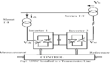
OPERATING PRINCIPLE OF UPFC
Available Online at www.ijpret.com 722
Fig. No. 1
III.BASIC OPERATING MODES OF UPFC
A] Shunt inverter: The shunt inverter is operated in such a way as to draw a controlled current from the line.
1. VAR Control Mode:In var control mode the reference input is an inductive or capacitive var request. The shunt inverter control translates the var reference into a corresponding shunt current request and adjusts the gating of the inverter to establish the desired current.
2. Automatic Voltage Control Mode:
The shunt inverter reactive current is automatically regulated to maintain the transmission line voltage at the point of connection to a reference value. For this mode of control, voltage feedback signals are obtained from the sending end bus feeding the shunt coupling transformer. The series inverter controls the magnitude and angle of the voltage injected in series with the line to influence the power flow on the line. The actual value of the injected voltage can be obtained in several ways.
B]Series inverter: The series inverter controls the magnitude and angle of the voltage injected in series with the line. This voltage injection is always intended to influence the flow of power on the line, but the actual value of the injected voltage can be determined in several different ways. These include:
1. Direct Voltage Injection Mode:
The reference inputs are directly the magnitude and phase angle of the series voltage.
2. Phase Angle Shifter Emulation Mode:
Available Online at www.ijpret.com 723
3. Line Impedance Emulation Mode:
The reference input is an impedance value to insert in series with the line impedance.
4. Automatic Power Flow Control Mode:
The reference inputs are values of P and Q to maintain on the transmission line despite system changes[1].
IV. SYSTEM WITHOUT UPFC
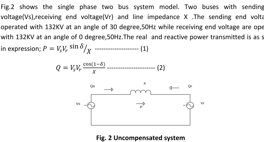
Fig.2 shows the single phase two bus system model. Two buses with sending end voltage(Vs),receiving end voltage(Vr) and line impedance X .The sending end voltage is operated with 132KV at an angle of 30 degree,50Hz while receiving end voltage are operated with 132KV at an angle of 0 degree,50Hz.The real and reactive power transmitted is as shown
in expression; 𝑃 = 𝑉𝑠𝑉𝑟sin 𝛿⁄𝑋 --- (1)
𝑄 = 𝑉𝑠𝑉𝑟cos(1−𝛿)
𝑋 --- (2)
AC AC
Vs Vr
X
Qs Qr
P
Fig. 2 Uncompensated system
The simulation model without UPFC is as shown in Fig3.The real and reactive power transmitted of sending end is as shown in Fig4.The real and reactive power of receiving end is shown in Fig 5.
Available Online at www.ijpret.com 724
Fig.4 Sending end real and reactive power
Fig.5 Receiving end real and reactive power
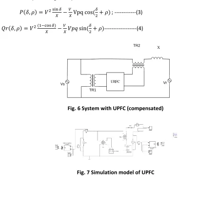
V. SYSTEM WITH UPFC
Fig.6 shows single phase two bus system with UPFC. The sending end voltage is operated with 132KV at an angle 𝛿= 30 degree,50Hz while receiving end voltage is operated with 132KV at an angle of 0 degree,50Hz. The transformer TR1 connected in shunt with the transmission line and transformer TR2 connected in series with the transmission line with 3:1 ratio. The two inverter are connected with a separate battery (instead of coupled capacitor). The shunt inverter, known as staticsynchronous compensator (STATCOM), injects an almost sinusoidal current, of variable magnitude, at the point of connection. The second inverter, known as Static Synchronous Series Compensator (SSSC) injects an almost sinusoidal voltage, of variable magnitude, in series with the transmission line. When the STATCOM and the SSSC operate as stand-alone devices, they exchange almost exclusively reactive power at their terminals. While operating both the inverters together as a UPFC, the exchanged power at the terminals of each
0 0.1 0.2 0.3 0.4 0.5 0.6 0.7 0.8 0.9 1
0 2 4 6x 10
7 Time(sec) R e a l P o w e r
0 0.1 0.2 0.3 0.4 0.5 0.6 0.7 0.8 0.9 1
0 5 10x 10
6 Time(sec) R e a c ti v e P o w e r
0 0.1 0.2 0.3 0.4 0.5 0.6 0.7 0.8 0.9 1
0 2 4 6x 10
7 Time(sec) R e a l P o w e r
0 0.1 0.2 0.3 0.4 0.5 0.6 0.7 0.8 0.9 1
-3 -2 -1
0x 10
Available Online at www.ijpret.com 725
inverter can be reactive as well as real. The exchanged real power at the terminals of one inverter with the line flows to the terminals of the other inverter through the common DC link.Fig.7 shows the simulation model of UPFC. The shunt inverter is operated in such a way as to draw a controlled current from the line. The series inverter provides main function of UPFC by injecting a voltage 𝑉𝑝𝑞 and phase angle 𝜌 via series transformer. Here the injected 𝑉𝑝𝑞and
𝜌=10 degree.The sending end real and reactive power is as shown in Fig.8. The receiving end real and reactive power is as shown in Fig.9.Simulation results show the effectiveness of UPFC to control the real and reactive powers. It is found that there is an improvement in the real and reactive powers through the transmission line when UPFC is introduced. The expression for real and reactive power is given by
𝑃(𝛿, 𝜌) = 𝑉2 sin 𝛿
𝑋 −
𝑉
𝑋Vpq cos( 𝛿
2+ 𝜌) ; ---(3)
𝑄𝑟(𝛿, 𝜌) = 𝑉2 (1−cos 𝛿)
𝑋 −
𝑉
𝑋𝑉𝑝𝑞 sin( 𝛿
2+ 𝜌)---(4)
Vs UPFC Vr
X TR2
TR1
Fig. 6 System with UPFC (compensated)
Available Online at www.ijpret.com 726
Fig.8 Sending end real and reactive power
Fig.9 Receving end Real and reactive power
Single phase Ps(MW) Qs(MVAr) Pr(MW) Qr(MVAr)
Without upfc 59MW 9.66 MVAr 56MW -21.18
MVAr
With upfc 64MW 23.47 MVAr 62.13MW -5.16
MVAr TABLE I
0 0.1 0.2 0.3 0.4 0.5 0.6 0.7 0.8 0.9 1
-5 0 5 10x 10
7 Time(sec) R e a l P o w e r
0 0.1 0.2 0.3 0.4 0.5 0.6 0.7 0.8 0.9 1
-1 0 1 2 3x 10
7 Time(sec) R e a c ti v e P o w e r
0 0.1 0.2 0.3 0.4 0.5 0.6 0.7 0.8 0.9 1
0 2 4 6 8x 10
7 Time(sec) R e a l P o w e r
0 0.1 0.2 0.3 0.4 0.5 0.6 0.7 0.8 0.9 1
-6 -4 -2 0 2x 10
Available Online at www.ijpret.com 727
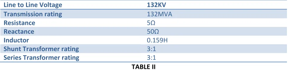
Simulation parameter of single phase system
Line to Line Voltage 132KV
Transmission rating 132MVA
Resistance 5Ω
Reactance 50Ω
Inductor 0.159H
Shunt Transformer rating 3:1
Series Transformer rating 3:1
TABLE II
Table I shows comparison of power flow in without and with UPFC system. Table II shows the simulation parameter used in simulation circuit.
VI .CONCLUSIONS
The basics of FACTS device UPFC are discussed.In this paper the (UPFC) simulation study, matlab simulink is used to simulate the model of UPFC connected to a single phase transmission system. By comparing the results of uncompensated and compensated system it shows the improvement in real and reactive power when UPFC is installed in the circuit. The UPFC system has the advantages like reduce maintenance and ability to control real and reactive powers.
ACKNOWLEDGMENT
The author would like to thank department of Electrical Engineering of Ramdeobaba College of Engineering And Management.
REFERENCES
1. C. D. Schauder, E.M.Hamai, "Operation of unified power flow controller (UPFC) under practical constraints", IEEE Trans. Power Del., vol. 13, no. 2, pp.630 -639 1998
2. R. Mihalic, "Improvement of transient stability using unified power flow controller", IEEE Trans. Power Del., vol. 11, no. 1, pp.485 -492 1996
Available Online at www.ijpret.com 728
4. Parvej khan, Himmat singh “Power Flow Control In A Transmission Line Through UPFC” International Journal of Engineering Research and Applications (IJERA) ISSN: 2248-9622 www.ijera.com Vol. 2, Issue 3, May-Jun 2012.
5. Sunil Kumar A V, Roopa V, Javid Akthar, Dr. Shivasharanappa G C,“Transmission Loss Allocation and Loss Minimization By Incorporating UPFC in LFA” International Journal of Modern Engineering Research (IJMER) Vol.1, Issue.1, pp-236-245.
6. Amit Shiwalkar and N.D.Ghawghawe, “Power flow control through transmission line with UPFC to mitigate contingency”, ISSN (Print): 2278-8948, Volume-1, Issue-2, 2012.
7. K. K. Sen, Eric J. Stacey, "UPFC-unified power flow controller: Theory, modeling and applications", IEEE Trans. Power Del., vol. 13, no. 4, pp.1453 -1460 1998.
8. N. G. Hingorani & Naren “Understanding FACTS”IEEE Press, 2000.
9. Dr. Arvind Kumar Singh, “modelling of single phase upfc without dc capacitor ISSN: 0975-5462 Vol. 3 No. 5 May 2011.