Scalable Computing: Practice and Experience
Volume 18, Number 4, pp. 313–330. http://www.scpe.org
ISSN 1895-1767 c
⃝2017 SCPE
TESTING AND VALIDATION OF MODBUS/TCP PROTOCOL FOR SECURE SCADA COMMUNICATION IN CPS USING FORMAL METHODS
IRFAN A. SIDDAVATAM∗, SACHIN PAREKH, TANAY SHAH, AND FARUK KAZI
Abstract. Cyber-Physical Systems (CPS’s) evident representation is Supervisory Control, and Data Acquisition(SCADA). As SCADA is being refurbished with advanced computing and communication technologies, the risk involved in adopting/updating to new technology needs to be validated and verified thoroughly. One of the greatest challenges is security testing of protocols. All CPS systems being live and attached to physical process can not be scheduled for penetration testing and verification. This paper presents design and implementation of industrial compliant SCADA test bed, the formal analysis of semantics and security of Modbus/TCP protocol using Coloured Petri Nets(CPN) tool. A novel method is proposed to differentiate attack vector by identifying influential nodes using formal concept analysis. Modbus/TCP conceptualized attack from analysis is tested and verified on the test bed.
Key words: Coloured petri net, Cyber-physical system, Formal analysis, Modbus/TCP, Communication protocol, SCADA. AMS subject classifications. 68M12, 14D15, 14D15
1. Introduction. Cyber-Physical Systems(CPS) are highly integrated engineering systems, with a para-mount requirement of cohesion and coupling between its computing, communication and control technologies. They have to deal with the physical system with the stringent basis of robustness, efficiency, stability and reli-ability [1, 2]. CPS have representation in a broad range of areas, like a small scale example of medical devices [3] to large scale CPS of a power grid. CPS perspective of the power grid has received a lot of attention in the research community, as the cyber system embedded in the communication network, substation automation, and control center takes the responsibility to provide safe, secure and efficient transmission, distribution and reliable generation [4]. The smart grid is the next generation of a power grid that will have all IT communi-cation architecture from substation automation along with SCADA to home area network based on Ethernet communication protocol[5].
In our current time, pressing challenges to handle CPS developed on legacy control systems are its vul-nerability and patch management. SCADA being an integral part of CPS system, it’s vulvul-nerability risk while connected to the public network like the Internet have been known [6]-[16]. SCADA system if compromised will have the severe impact on the power system. It is possible to formulate an attack that can launch vicious switching actions causing disruption in load. Such scenario may be more grievous if the attacker can penetrate the control center of the SCADA system [17]. Till date keeping these machines functional was the prime focus but now making it secure is the biggest challenge. According to SANS Institute survey, 70% of SCADA sys-tem operators weigh the risks to be high to severe, and 33% speculate that they may have had incidents [18]. Numerous reports reveal SCADA systems are under increasing attack and are vulnerable. The widely known incidences are Night Dragon Remote Access Trojans (RATs) infected Exxon, Shell, BP, and others for data stealing/spying, Stuxnet infected Iran’s Natanz nuclear facility and disrupted nuclear centrifuges, Ukrainian power companies experienced attacks on distribution substation affecting 225,000 customers [19]-[24]. Further, the security breach is exploitation of flaws existing in a system or due to inappropriate update carried out. The basic thumb rule for up-gradation is to ‘risk implementing an upgrade should be less than not implementing’. Main contribution of this paper are:
Contribution 1: In CPS, system development or up-gradation is the critical task. As Modbus/Remote Ter-minal Unit(Modbus/RTU) runs on serial communication, it is considered to be secured but if it is upgraded to Modbus/Transmission Control Protocol(Modbus/TCP) will turn the system vulnerable to cyber-attack. To understand the impact, we contribute by providing formal specification model of Modbus/TCP using CPN and perform its security analysis.
Contribution 2: Our contribution is focused towards verification by the approach of testing assumptions and not by testing everything. Standard assumptions like unreliable communication channel that are
∗Electrical Department, Veermata Jijabai Technological Institute, H R Mahajani Marg, Matunga, Mumbai, Maharashtra, India 400031 ([email protected]).
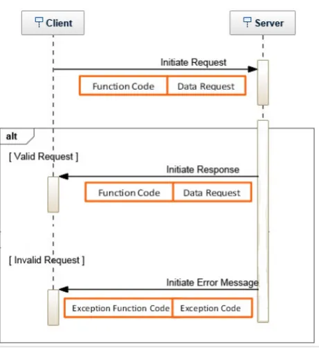
Fig. 2.1.Client-Server interaction
required for security assurance of protocol are tested. Our novel method performs state space analysis using CPN which is developed to verify and validate the concept of attack using formal concept analysis.
Contribution 3: With many of the SCADA systems being significantly dated, security was little concern before today’s internet age, for this reason, most control systems are open to attack from the outside. We contribute towards mitigation of this risk by the development of SCADA test bed that can be used for security evaluation, testing, and simulations.
Contribution 4: Deceptions attack vector conceptualized from modeling is tested experimentally on research platform; a proposed solution for mitigation of attack on SCADA is demonstrated.
2. Security Analysis of Modbus/TCP Protocol.
2.1. Modbus/TCP Protocol. In 1979, Modicon developed Modbus protocol for communication over single twisted pair cable with many devices. Modbus was originally designed for RS232, and it is also adapted for RS485. Modbus protocol has true multi-drop network along with faster speed over longer distances. It is now royalty-free protocol. Modbus works in master-slave mode, wherein master can communicate with one or many slaves. Master or Client can initiate a transaction (called query) to which slave or server responds by providing requested data. A slave is sensing or measuring device like I/O transducer, valve, network drive, or other measuring instruments which processes information and sends its output to the master using Modbus.
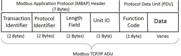
The general Modbus frame has two data units. First, Application Data Unit(ADU) that deals with com-munication layer and also has additional fields to map protocol on specific bus or network. Second, Protocol Data Unit(PDU) is initiated by the client for the transaction. The query contains a server address, a function code specifying the action to be carried out, data and error checking field. As shown in Figure 2.1, if the server receives PDU appropriate to a request with no error, it responds back confirming action performed, data and error checking field. In case if an error is detected in operation, the server responds by sending exception function code and exception code. Modbus/TCP is simply the Modbus/RTU protocol with a Transmission Control Protocol(TCP) interface that runs on ethernet.
Fig. 2.2.Modbus/TCP frame format
Transaction/invocation Identifies (2 Bytes): On same TCP connection, if the client wants to send multiple messages without waiting for responses, transaction identifier field is used for pairing such request. Protocol Identifier (2 Bytes): This field is set to ‘0’ for Modbus services, for the future extension all other are
kept reserved.
Length (2 Bytes): Length field contains byte count of all the remaining fields including the data field, function code, and unit identifier byte.
Unit Identifier (1 Byte): If a remote server is located on non-TCP/IP network, unit identifier field identifies it. In the case of Modbus TCP/IP server application, the unit Identifier is set to ‘00 or FF’.
Function Code (1 Byte): The function code is an indication of the type of action server has to perform. The function code field of a Modbus/TCP data unit has the length of one byte. The correct hexadecimal function codes are in the range of 1 - 127, while remaining are kept reserved and used as exception responses ( 128 - 255 Hex). Function code cannot have value ‘0’ [25, 26].
2.2. Formal Modelling of Protocol.
2.2.1. Description of Protocol. As explained in the previous section, Modbus/TCP communication involves two entities, i.e., client and server. The client is the initiator of communication and displays result obtained from the server. Modbus/TCP protocol fields as Transaction identifier, Protocol identifier, Length, Unit-identifier facilitates the establishment of a connection between client and server. These fields remain agnostic to a behavior of process hence are ignored in modeling semantic.
Modbus/TCP protocol consists of three types PDU; Request PDU is initiated by a client, and it includes parameter function code and request data. The Response PDU is generated by a server having function code and data, and Exception PDU contains exception code in case of error. Accordingly, Modbus/TCP client pro-cess can be formally described as:
Client Process: A Client process equipped with function codefc and datada and using server device ‘b’ is:
Client(a, fc, da) =
− env?b:Device→send.a.b⟨fc, dc⟩
−
fc∈F
dc∈D
ec ∈E
recives.b.a{fc, dc} →ST OP
recives.b.a{fc, dc, ec} →ST OP
The transition rules for external choice ‘’ reflect the fact that the first external event resolves the choice in favor of the process performing the event.
Server Process: The server role has a program that validates the ‘fc’ and ‘dc’ value received, successful exe-cution of a function and then responds accordingly. we get the following descriptions:
Server(b, fc, da) =
fc∈F
dc∈D
ec∈E
recives.a.b{fc, dc} →
|notV alid.fc →send.b.a{fc, dc, ec} →ST OP |notV alid.fc.dataAddress→send.b.a{fc, dc, ec} →ST OP |notV alid.dc →send.b.a{fc, dc, ec} →ST OP |notExecuted.fc→send.b.a{fc, dc} →ST OP |send.b.a{fc, dc, ec} →ST OP
Obviously, in this case, it is not the server process’s instigates the protocol, but rather it is started when it receives a message from an initiator. The server executes function code validates each parameter and its possible execution on a device if any error occurs appropriate exception is raised and send to the client. In case of proper request and execution of a command, the response contains values of ‘fc’ and ‘dc’ executed on the devices.
Attacker Process: The security concerns of the protocol are modeled by adding an attacker or intruder process into the network. Further, through out the literature term, attacker and intruder are interchangeable. The attacker can tamper with the messages that pass around. Intruder process has a knowledge K
that contains information such as members involved in the operational network, protocol details, etc. It can listen to message flow all the time. The attacker can formulate messages inferringK that it has gathered over a period and the messages received till that moment.
Attacker(X) =learn?c:commands→Attacker(deduce(X∪ {c})) − say?m:X∩messages→Attacker(X)
Here, the parameter X ranges over function code ‘fc’ and data ‘dc’ all PDU that attacker can generate. ‘commands’ is the subset of fact that represent all PDU that might be generated or accepted over the communication medium by process. The function deduce(X) calculates all PDU developed from X.
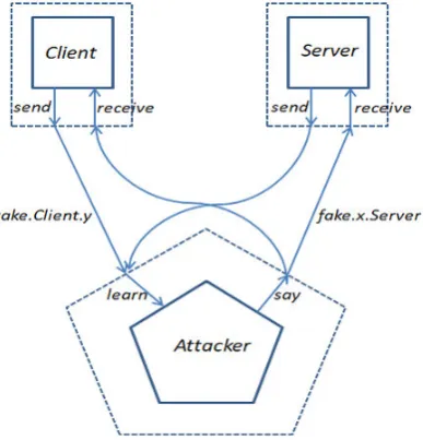
Network Model: The network consist of three entities Client, Server and Attacker.There are different models of interconnection used to put together these entities [28]. We have modelled the intruder as being the communication medium. This network is connected together via renaming that match up the re-ceive:a:b: m rere-ceive:a:b:m and send:a:b:m events performed by agent and server processes with the
say:m and learn:m events of the intruder. The send and learn channels are connected by renaming them both to a take channel, and the receive and say channels are connected by renaming them to a
fake channel. Network combined together is described below:
Client[[f ake, take/receive, send]] |||Server[[f ake, take/receive, send]]
− ∥Attacker[[take.x.y, f ake.x.y/learn, say|x, y∈ {Client} ∪ {Server}]]
Figure 2.3 shows this network, the dotted lines represent attacker channel inclusion by renaming, to keep thing simple only a subset of the channel names are included in the diagram.
Fig. 2.3.Network with attacker included
CPN [30], as a derivative combines these capabilities of Petri nets with a high-level programming language, Standard Meta Language(SML) [31, 32] to provide the primitives for defining data types, data manipulations and creating compact graphical models.
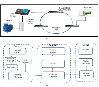
2.3.1. CPN Block Diagram for Modbus/TCP Scenario. Modbus/TCP is complete protocol suite that caters to all range of industrial device as RTU, Intelligent Electronic Device(IED), Variable Frequency Drives(VFD) and many other. Depending upon the nature of the application, client issues function code as the request that set or read required data model. As a test case, we model scenario that writes single register. A most widely used industrial application for this situation is, VFD set from the operator workstation to run an induction motor at the required speed. Figure 2.4(a) show typical set up for mentioned scenario and Figure 2.4(b) shows block diagram for CPN model. The requests are formed with packets at client then transmitted through the network. As the request passes through the network it can be tampered by the attacker or can just be passed on depending upon the criticality of the command. As the server receives the command, it is validated then passed on for processing. In the case of error, the exception is raised and the response is formulated with the error code. If the request is properly processed, response consists of function code and the current value of the device after execution of the command. The function codes and other parameters of Modbus/TCP are used for modelling with data, functions, and headers to mimic actual behaviour of the protocol.
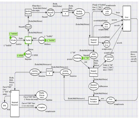
2.3.2. CPN Tool Initial Model . An initial model developed is to validate and analyse general behaviour of Modbus/TCP protocol under no threat condition. The model describes normal behaviour with all error condition being simulated. Figure 2.5 is complete model developed in CPN Tools version 4.0.1.
Fig. 2.4. (a) Implementation scenario (b) CPN Block diagram
register address assigned. Functionerrorcode figures out if the exception is raised.
B. Operations: Figure 2.5 depicts initial model for Modbus/TCP protocol for the scenario wherein client executes the command that writes single register of the severing device. In this figure, the client station composes a request and transmits the request through the network to the server. The initial composition of a request is through following Datasource or Place: ‘Funcode’ , ‘RAddress’ and ‘RegValue’ . These places have markings that form the initial state of CPN model. The occurrences of the markings create a token on Place ‘Request’ . ‘Request’ is assigned with a color set ‘Request’. Colour set ‘Request’. is a product of the data type ‘fcode’, ‘RAdd’ and ‘RegValue’ . Similarly, when the incoming arc of the transition Sending Request is satisfied, tokens ‘fcode, RAdd, RegValue’ is created representing request packet formation. The major transitions that need to satisfied are:
Sending Request: The transition has Boolean flag ‘fstat’ to be satisfied to place token further. The flag represents a satisfied establishment of a connection by the TCP protocol.
Received Request: It is one of the important transaction; it validates token for correct function code, register address, and register value. The evaluation is carried out using the function declared as shown in Figure 2.6, if Request with error is encountered, error token is passed.
Request Processing: This transition models the behavior where in error token is raised if the processing of valid token fails.
Error Response: Transition captures the type of error occurred and passes on exception code raised.
Response Formation: In Modbus/TCP, the response is generated in both cases for normal execution and even if the exception is raised. Transition fires according to token arrived to form appropriate response token.
Fig. 2.5.CPN initial model
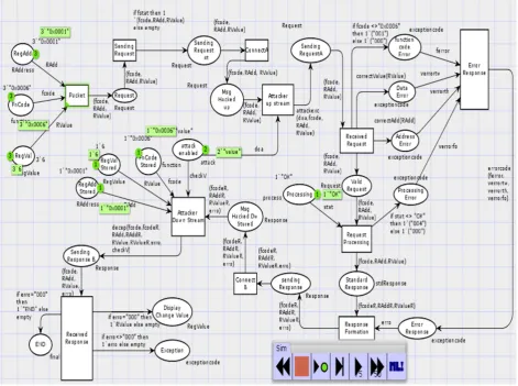
explained in Sect. 2.2.1. Figure 2.7 elaborates in detail the attack model.
A. Declaration: Attack Model includes Place ‘Attack Enable’ , this Place decides the mode of commu-nication channel. Mode of commucommu-nication channel can be changed by setting ‘value’ token of Place ‘Attack Enable’ . Channel can be configured into following ways. 1. ‘General Mode’ by keeping the token ‘empty’, in this mode the model behaves as ‘Initial Model’. Communication channel works as reliable and secure medium, having no attack generated. 2. If string ‘insecure’ is set as the token, channel turns to be insecure and false data injection attack is executed. The attack changes variable ‘RValue’ to predefined value intend to cause damage in physical system. 3. In this mode Denial of Service(DoS) attack is executed, by setting token ‘add’ or ‘code’. Here set token changes the value of ‘RAdd’ or ‘fcode’ causing a legitimate PDU to converted into erroneous PDU intern avoiding the server to respond in the required manner.
B. Operations: Figure 2.7 describes complete details of Attack Model. Following are the transitions that play a significant role in the operation of model:
Fig. 2.6.Declared function in initial model
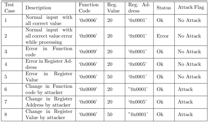
Table 2.1
Test case for Verification
Test Case Description Function Code Reg. Value Reg.
Ad-dress Status Attack Flag
1 Normal input with
all correct value ‘0x0006’ 20 ‘0x0001’ Ok No Attack
2
Normal input with all correct value error while processing
‘0x0006’ 20 ‘0x0001’ Error No Attack
3 Error in Function
code ‘0x0009’ 20 ‘0x0001’ Ok No Attack
4 Error in Register
Ad-dress ‘0x0006’ 20 ‘0x0005’ Ok No Attack
5 Error in Register
Value ‘0x0006’ 50 ‘0x0001’ Ok No Attack
6 Change in Function
code by attacker ‘0x0009’ 20 ”0x0001’ Ok Attack
7 Change in Register
Address by attacker ‘0x0006’ 20 ‘0x0005’ Ok Attack
8 Change in Register
Value by attacker ‘0x0006’ 50 ”0x0001’ Ok Attack
request PDU is defaced.
Attack Down Stream: In the second phase, a response from the server regarding a status of the request needs to be altered. Forementioned is needed to hide attack execution from the client. Transition ‘Attack Down stream’ replaces tampered request with the original one.
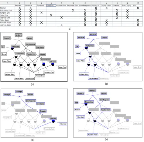
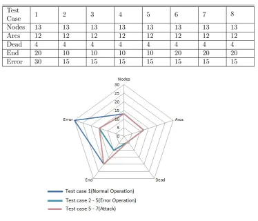
2.3.4. Model Validation and Verification. The aim of this section is to validate and verify the correct-ness of the Modbus/TCP protocol and the attack model. We carry out a different set of the protocol run with the various set of token that simulates the normal behavior and behavior under attack. Multi-set tokens could have been used, but to keep understanding clean and simple single set is used to formulate one PDU transaction. Table 2.1 shows different combination of inputs and expected activation of the features. At this point, data generated by state space analysis need to be analyzed. We choose Formal Concept Analysis (FCA) widely used by information scientists as it performs data analysis, information management, and knowledge representation [33] [35]. State space report generated for the test case indicates the flow of token at each place. As per the concept of FCA, we consider test case example ‘function attack’ as the ‘formal object’ and Places that carry token during simulation as the ‘formal attribute’. A combined set of the object in relation with the attribute is called as ‘formal context’ shown in Figure 2.8.a. One of the primary benefits of FCA is we can visualize the context in line diagram called as ‘concept lattice’. The context for our test case shown in Figure 2.8.a can be represented by concept lattice shown in Figure 2.8.b. Concept lattice is the formation of set concepts of a formal context and the sub-concept and super-concepts relation between the concepts. As shown in figure node represents the concept, in our case for example normal operation represented by node ‘normal’ representing concept; similarly, we have concepts ‘value attack’, ‘error value’ , ‘function attack’ so on and so forth. We can further drill down to understand the associated concept called as subconcept and the attribute.
Fig. 2.8.(a) Formal context (b) A concept lattice for the formal context in figure a (c) A subconcept-superconcept relation for ‘Normal ’ node (d) A subconcept-superconcept relation for ‘Error value ’ node (e) A subconcept-superconcept relation for ‘Function attack ’ node
Table 2.2
State space for Results
Test
Case 1 2 3 4 5 6 7 8
Nodes 13 13 13 13 13 13 13 13
Arcs 12 12 12 12 12 12 12 12
Dead 4 4 4 4 4 4 4 4
End 20 10 10 10 10 20 20 20
Error 30 15 15 15 15 15 15 15
Fig. 2.9.Graph showing attack pattern
3. CPS Test bench. As described by Rajkumar et al. [1] CPSs is physical and engineered systems, whose operations are monitored, coordinated, controlled, and integrated by a computing and communicating core. There is definite requirement in research community for having Cyber-Physical Testbed, that aims towards following objective:
1. Design and implementation a SCADA bench for security evaluation, testing, and simulations are nec-essary to guarantee the safety of our critical infrastructure.
2. Comprehend the impact of cyber-attack such as false data injection, unauthorized command execution, denial of service(DoS) attack, etc. and discover variant for CPS.
3. Testbed that integrates industry standard hardware, software, and Wide Area Measurement System (WAMS) components and protocols.
4. Platform that enables vulnerability assessment of WAMS and related devices.
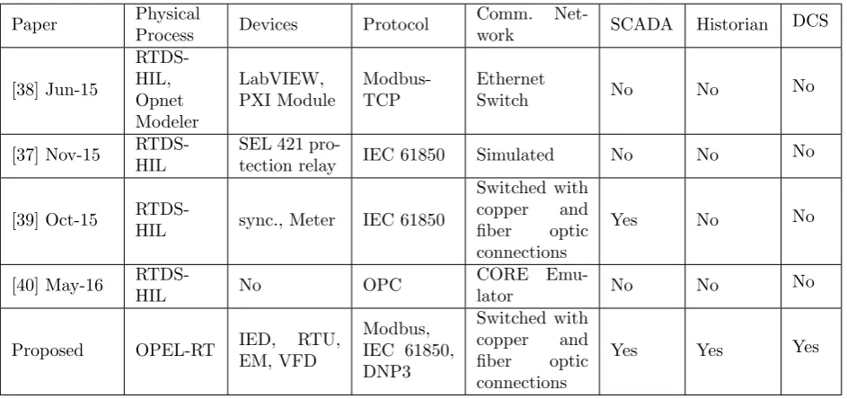
3.1. Survey of Cyber-Physical Test beds. The interoperability of devices and implementation of functions are the key focus during the construction of smart substations, utilities and manufacturers over cyber security issues and testing of same. Nevertheless, researchers around the world are making an effort on developing cyber-physical Testbed that can develop realistic solutions that can act as ‘hot fixes’ to the cyber security vulnerable industrial environment. In last one-two years, there are a good number of CSP Testbeds developed, few related are discussed further.
reconfig-Table 3.1
Comparison of existing CPS Test bed
Paper Physical
Process Devices Protocol
Comm.
Net-work SCADA Historian DCS
[38] Jun-15 RTDS-HIL, Opnet Modeler LabVIEW, PXI Module Modbus-TCP Ethernet
Switch No No No
[37] Nov-15 RTDS-HIL
SEL 421
pro-tection relay IEC 61850 Simulated No No No
[39] Oct-15
RTDS-HIL sync., Meter IEC 61850
Switched with
copper and
fiber optic connections
Yes No No
[40] May-16
RTDS-HIL No OPC
CORE
Emu-lator No No No
Proposed OPEL-RT IED, RTU,
EM, VFD Modbus, IEC 61850, DNP3 Switched with copper and fiber optic connections
Yes Yes Yes
urable system. Different types of traffic, such as DNP3 and C37.118.1 PMU data that could be passed through the cyber network emulated in ns-3. In work by Bo Chen et al. [38] RTDS is used to carry out power system simulation, while SCADA and IEDs are simulated using LabVIEW and PXI modules. Paper by Y. Yang et al. [39] discussed the development of cyber-physical test bed that examine the IEC 61850 based smart substations for the impact of cyber-attack and potential cyber security vulnerabilities. V. Venkataramanan et al. [40] de-veloped a real-time, cyber-physical co-simulation using RTDS and Common Open Research Emulator(CORE) to simulate power system and emulate communication network respectively. In work by Uttam Adhikari et al. [41], RTDS hardware-in-loop(HIL) is used to simulate physical process for developed WAMS cyber-physical test bed. Table 3.1 compares presented test bench with existing ones.
3.2. System Description. Testbed should include hardware components, control and configuration soft-ware packages, communication networks and protocols, and custom softsoft-ware for applying stimulus and capturing data. The developed Testbed uses communication protocols, software, and hardware that conforms to industry standard. Industrial Control System(ICS) is most referred the case of Cyber-physical system; CPS testbed developed tries to cover all aspect of ICS with electrical system as the physical process. Distributed control system(DCS), SCADA and other control systems those usually found in industrial sectors and critical infrastruc-tures like Programmable logic controllers(PLC) fall under the broad category of the ICS. The primary difference between SCADA and DCS or PLC controlled sub-systems is, former are geographically dispersed while later are confined to factory or plant-centric area. Local area network(LAN) technologies used by DCS and PLC are more high speed and reliable in comparison to the long-distance communication systems employed by SCADA [42]. Figure 3.1 shown is schematic of cyber-physical testbed developed in-house. Each of the components of the testbed is described in following sections.
3.2.1. Physical System. A core aspect of any cyber-physical system is its physical process. The developed testbed uses real-time HIL OPEL-RT simulator OP5600-eMegaSim. OP5600 is used to simulate up to 30 bus power system. There is a constraint on the size of the system but modeled system very precisely imitate the behavior of real power system. The simulator supports C37.118, IEC 61850 protocol stack for communication with laboratory devices and monitoring system.
Fig. 3.1.System architecture of CPS test bed
of Emerson make. Installed system has a simplex controller, 8 wide I/O interface carrier, Smart wireless gateway 1420 (Copper Ethernet connection, locally mounted antenna), Analog Input/Output, 16 channel, 4 - 20 mA, HART, Discrete Input, 32 channel, 24 V DC, Discrete Output, 8 channel, 24 V DC and DeltaV PredictPro 20 MPC Outputs software. The SCADA Testbed developed has all facets of industrial grade devices. The system supports DNP3, Modbus, IEC 60870-103, 101, and IEC 61850 protocol for communication. GPS clock of SYNTIME make with 10/100 MBPS NTP/SNTP output is used for the time synchronization of the relays and the status points at different locations. A high-speed data is achieved by industry standard networking having an optical fiber backbone operating at 100 Mb per second. The control center was designed to meet the research and training requirement. The iVisionmax is the SCADA software used in the laboratory. The iVisionmax supports major equipment and protocol. Few critical devices are listed below:
Phasor Measurement Unit: PMU measures on the global time reference the magnitude and phase angle of an analog and /or drived phasor, as per the synchrophasor standards (IEEE 1344, IEEE C37.118). Vizimax PMU010000 is installed, it has been tailor made to be compatible with OPL-RT from OEM itself. OSI-PI: The PI System is historian and also has its ability to collect, analyze, visualize and share large amounts
of high-fidelity, time-series data from multiple sources to people and systems across all operations. Network: As per industrial standard communication channel is of Fiber optic cable(FOC). To have fault tolerant
network, ring topology of IEC 61850-3 compatible Hirschmann Layer-2 switches are formed. Segregation of control network and Corporate is achieved with the help of Layer-3 CISCO Switch.
PLC (Siemens S7 1200): Programmable logic controller is used as a local controller. Ladder programming is used with Simatic S7 TIA portal to program a PLC.
Modbus/TCP Gateway: A Modbus/TCP gateway is used as a protocol converter, which encapsulates a Modbus -RTU frame into Modbus/TCP packets to communicate with server and workstation.
Fig. 3.2.Test bench
4. Experimentation and Results.
4.1. Implementation of Formally conceptualised Deception attack on Modbus/TCP. Vulner-ability mentioned in Sect. 2.3 for Modbus/TCP is exploited to form attack vector. This attack execution methodology and its outcomes are explained in following section.
4.1.1. Discovery. Discovery is the initial phase where all information regarding network is gathered. The focus is to know network architecture, communication protocol, etc. Discovery phase is carried out for both phases of attack Upstream and Downstream or deception. Modus operandi for discovery phase is as follows:
ST EP −1 : Nature of attack considered is of type ‘Insider Attack’ wherein the attacker has access to any of the computers on the control network. The attacker has the access physically or gained remote access due to a compermised machine.Attacker maps all devices connected to the network in terms of IP address of the network, port accessed and other network parameters.
ST EP −2 : In this step, we carry out the Man in the Middle(MITM) attack on each of the connected devices for a fixed time ‘t’ . MITM enables us to sniff the communication between all devices on the network. Increasing the time ‘t ’ helps to get more data to analyze while decreasing ‘t’ decreases the probability of detection.
ST EP −3 : In the final step, we analyze the sniffed data to identify the network architecture. Fig.4.1(a) shows result of sniffing data on experimental setup shown in Fig.4.1(b). It is quite evident from frequency analysis of communication, and one can detect protocol and interacting devices. For the experimental setup, IP address for SCADA server is 192.168.0.21 and Modbus gateway as 192.168.0.20 communicating over Modbus/TCP. Forementioned communication pattern could be easily detected as histogram shows concentrated Modbus/TCP packets with these IP’s.
4.1.2. Deception Attack. Deception attack is a combination of MITM and Denial of Service(DoS) attack. It modifies operations of the field device in such a manner that changes in operations are not reflected at SCADA HMI. The attack may lead to a delayed or no control action being taken by supervisory control, causing failure in the system. The execution steps to formulate attack are as follows:
Step 1: Initial step is to footprint the target network. The result of discovery phase lead us following pointer : • As there was a convergence of communication at the particular device, indicated network consists of
the gateway.
• IP address of network machines were enumerated.
• Frequency of communication suggested the presence of SCADA server and gateway.
Fig. 4.1.(a) Experimental set-up for Modbus attack; (b) Packet analysis network
Fig. 4.2.(a) Execution draft of deception attack inferred from network footprint (b) Deception attack executed
and gateway through the host computer. Now the host computer fires unauthorized change of frequency command to VFD.
Step 3: Next action depicts response that will reach SCADA server due to the unauthorized change in VFD frequency. Response packets from gateway are crafted to standard frequency. The challenge is, to keep a check on the integrity and validity of the received data. The server assures validity response by comparing the transaction identifier of the reply and query. This check was breached by forming a coun-terfeit response that crafts in real time with transaction identifier reproduced from the corresponding query.
Fig. 4.3.(a) Modified lab set up; (b) Packet analysis for modified lab set up
4.2. Mitigation of Modbus Attack. The major vulnerabilities of Modbus/TCP protocol identified are as follows :
• If Modbus/TCP data is modified it does not affect the TCP checksum of the packet, hence making it easy to compromise the integrity of the data.
• Modbus/TCP protocol has no encryption, due to which packets can be easily modified by analyzing previous packets captured.
• A Modbus/TCP slave interprets the Modbus/TCP data and does authenticate master, making it vul-nerable.
The above vulnerabilities are related to Modbus/TCP protocol implementation. However, this work does not try to mitigate protocol vulnerabilities.
We propose a systemic view, where in detection of concentrated Modbus/TCP protocol can be deceived. Fig. 4.1(b) shows packet analysis for network help to identify Modbus/TCP communication and devices involved. Fig. 4.3(a) shows modified set up, where in ’Green’ circle marked to operator machine indicate it has been added with Modbus/TCP simulator with slave functionality and ’Red’ indicates Modbus master.
Now, if we gather footprints of network as shown in Fig. 4.3(b), identifying SCADA server and gateway becomes difficult, since we have neutralised Modbus/TCP traffic over the network. Further if discovery phase is not conclusive it becomes difficult to carry out targeted attack.
In future, the machines simulating modbus/TCP can monitored for ARP spoofing that may lead to detection of attacker.
REFERENCES
[1] R.Rajkumar, I.Lee, L.Sha, and J.Stankovic,Cyber-physical systems:the next computing revolution,Proceedings of the 47th Design Automation Conference. ACM, 2010, pp. 731736.
[2] K. Kim and P.R. Kumar,Cyber-Physical Systems: A Perspective at the Centennial,Proceedings of IEEE, 2012, pp. 1287-1308.
[3] I. Lee and O. Sokolsky,Medical cyber physical systems,Proceedings of 47thACM/IEEE Des. Autom. Conf., Jul. 2010, pp. 743748.
[4] Sridhar, S., Hahn, A., Govindarasu, M.,CyberPhysical System Security for the Electric Power Grid,Proceedings of the IEEE , vol. 100, no. 1, Jan.2012, pp. 210-224.
[5] Genge, B., Siaterlis, C.,Developing cyber-physical experimental capabilities for the security analysis of the future Smart Grid,Innovative Smart Grid Technologies (ISGT Europe), 2011 2nd IEEE PES International Conference and Exhibition on , pp. 1-7, 5-7 Dec. 2011.
[6] S. Zonouz, K. M. Rogers, R. Berthier, R. B. Bobba, W. H. Sanders and T. J. Overbye,SCPSE: Security-Oriented Cyber-Physical State Estimation for Power Grid Critical Infrastructures, IEEE Transactions on Smart Grid, vol. 3, no. 4, pp. 1790-1799, Dec. 2012
[7] Y. Mo et al.,CyberPhysical Security of a Smart Grid Infrastructure, Proceedings of the IEEE, vol. 100, no. 1, pp. 195-209, Jan. 2012.
[8] Gawanmeh, Amjad, Adel Bouhoula, Sofiene Tahar,Rank functions based inference system for group key management protocols verification, International Journal of Network Security 8, no. 2 (2009): 187-198.
[9] Mehr, Nima Sharifi, Christopher Dunn, Alexis Floyd, David James Kane-Parry, Volker Helmut Mosthaf, and Christopher Gordon Williams,Security verification by message interception and modification, U.S. Patent Application 15/422,253, filed February 1, 2017.
[10] Hollick, Matthias, Cristina Nita-Rotaru, Panagiotis Papadimitratos, Adrian Perrig, and Stefan Schmid,Toward a Taxonomy and Attacker Model for Secure Routing Protocols., ACM SIGCOMM Computer Communication Review 47, no. 1 (2017): 43-48.
[11] S. Liu, B. Chen, T. Zourntos, D. Kundur and K. Butler-Purry ,A Coordinated Multi-Switch Attack for Cascading Failures in Smart Grid, IEEE Transactions on Smart Grid, vol. 5, no. 3, pp. 1183-1195, May 2014
[12] G. Ericsson,Toward a framework for managing information security for an electric power utilityCIGR experiences, IEEE Trans. Power Del., vol. 22, no. 3, pp. 14611469, Jul. 2007.
[13] Chee-Wooi Ten, Chen-Ching Liu, Manimaran, G.,Vulnerability Assessment of Cybersecurity for SCADA Systems, IEEE Transactions on Power Systems, vol. 23, no. 4, pp. 1836,1846, Nov. 2008.
[14] Sridhar, S., Govindarasu, M.,Model-Based Attack Detection and Mitigation for Automatic Generation Control, IEEE Transactions on Smart Grid, vol.5, no.2, pp.580-591, March 2014.
[15] Ashok, A.; Govindarasu, M.,Cyber attacks on power system state estimation through topology errors, Power and Energy Society General Meeting, IEEE , pp.1-8, 22-26 July 2012
[16] J. Hong, C. C. Liu and M. Govindarasu, Integrated Anomaly Detection for Cyber Security of the Substations, IEEE Transactions on Smart Grid, vol.5, no.4, pp.1643-1653, July 2014
[17] Chee-Wooi Ten, Chen-Ching Liu, Manimaran, G.,Vulnerability Assessment of Cybersecurity for SCADA Systems, IEEE Transactions on Power Systems, vol. 23, no. 4, pp. 1836,1846, Nov. 2008.
[18] Matthew E. Luallen,SANS SCADA and Process Control Security Survey, A SANS Whitepaper, February, 2013 Available at : https://www.sans.org/reading-room/analysts.../sans-survey-scada-2013.
[19] H. Luiijf and R. Lassche,SCADA (on)veiligheid: Een rol voor de overhead, TNO/KEMA report,[Unclassified](June 2006), [20] M. Naedele and D. Dzung,Industrial information system security IT security in industrial plants An introduction, ABB
Review, issue 2, pp.6670, 2005.
[21] T. Smith,Hacker jailed for revenge sewage attacks, The Register, October 31, 2001.
[22] J. Visser, M. Berkom, J. Spiekhout, Y. Suurenbroek, J. Wessels, B. Smolders and C. Pietersen, Storing Gas-mengstation,Faults in Gas Mixing Stations, Technical Report CB-2-02.060, 2002.
[23] Christiansson, Henrik, and Eric Luiijf, Creating a European SCADA Security Testbed, International Conference on Critical Infrastructure Protection. Springer US, 2007.
[24] E-ISAC,Analysis of the Cyber Attack on the Ukrainian Power Grid, https://ics.sans.org/media/E-ISAC SANS Ukraine DUC 5.pdf, Website last accessed June 24, 2016.
[25] The Modbus Organization,Modbus Messaging on TCP/IP Implementation Guide V1.0a, Modbus Organization: Hopkin-ton, MA, USA, 2004. 24
[26] The Modbus Organization,Modbus Messaging on TCP/IP Implementation Guide V1.1a, Modbus Organization: Hopkin-ton, MA, USA, 2004. 24
[27] Derrick and John.,Concurrent and Realtime Systems: The CSP Approach. By Steve Schneider, Published by John Wiley and Sons Ltd., Chichester, UK, 2000. ISBN: 0471623733, 510 pages.
[28] Ryan, Peter, and Steve A. Schneider,The modelling and analysis of security protocols: the csp approach, Addison-Wesley Professional, 2001
[29] K. Jensen, L. Kristensen, and L. Wells,Coloured Petri Nets and CPN Tools for modelling and validation of concurrent systems, International Journal on Software Tools for Technology Transfer (STTT), vol. 9, no.3, pp. 213?254, 2007. [30] Kurt Jensen,Coloured Petri nets: A high level language for system design and analysis, Springer, 1991.
[31] M.R. Hansen and H. Rischel,Functional Programming in StandardML. Lecture Notes, 1997.
Press, 1(2):23,1997.
[33] Wille, Rudolf,Formal concept analysis as mathematical theory of concepts and concept hierarchies. ml, Formal concept analysis 3626 (2005): 1-33.
[34] Ganter, Bernhard, and Rudolf Wille, Formal concept analysis: mathematical foundations. ml, Springer Science & Business Media, 2012.
[35] Priss, Uta,Formal concept analysis in information science. ml, Arist 40.1 (2006): 521-543.
[36] Serhiy A. Yevtushenko,System of data analysis Concept Explorer,(In Russian). Proceedings of the 7th national conference on Artificial Intelligence KII-2000, p. 127-134, Russia, 2000.
[37] C. B. Vellaithurai; S. S. Biswas; A. K. Srivastava,Development and Application of a Real-Time Test Bed for Cyber-Physical System, IEEE Systems Journal ,no.99, pp.1-12 36
[38] B. Chen, N. Pattanaik, A. Goulart, K. L. Butler-purry and D. Kundur,Implementing attacks for modbus/TCP proto-col in a real-time cyber physical system test bed, IEEE International Workshop Technical Committee on Communications Quality and Reliability (CQR), Charleston, SC, 2015, pp. 1-6. 36
[39] Y. Yang et al,Cybersecurity test-bed for IEC 61850 based smart substations, IEEE Power & Energy Society General Meeting, Denver, CO, 2015, pp. 1-5.
[40] V. Venkataramanan, A. Srivastava and A. Hahn,Real-time co-simulation testbed for microgrid cyber-physical analysis, Workshop on Modeling and Simulation of Cyber-Physical Energy Systems (MSCPES), Vienna, Austria, 2016, pp. 1-6. [41] U. Adhikari; T. MORRIS; S. Pan ,WAMS Cyber-Physical Test Bed for Power System, Cybersecurity Study, and Data
Mining, IEEE Transactions on Smart Grid
[42] Stouler, Keith, Joe Falco, and Karen Scarfone ,Guide to industrial control systems (ICS) security, NIST special publication 800.82 (2011): 16-16.
Edited by: Amjad Gawanmeh
Received: May 5, 2017