Amelia Carolina Sparavigna (Correspondence)
[email protected]
+This article is published under the terms of the Creative Commons Attribution License 4.0 Author(s) retain the copyright of this article. Publication rights with Alkhaer Publications. Published at: http://www.ijsciences.com/pub/issue/2017-03/
DOI: 10.18483/ijSci.1227; Online ISSN: 2305-3925; Print ISSN: 2410-4477
The GIMP Retinex Filter Applied to the Fabric
Fault Detection
Amelia Carolina Sparavigna
1
, Roberto Marazzato
2
1
Department of Applied Science and Technology, Politecnico di Torino, Torino, Italy
2
Visiting Staff at Department of Mathematical Sciences, Politecnico di Torino, Torino, Italy
Abstract: In this paper we are proposing the use of a Retinex filter, the GIMP Retinex, for improving the methods for fabric fault detection based on image processing. Since the Retinex filtering is simulating the human vision, it can act in the processing of the images as the trained staff of textile industry is acting in the visual inspection of fabrics on off-line stations. Here some examples are proposed. These examples show that an image preprocessing based on a Retinex filter can help any further analysis aimed to detect the presence of defects.
Keywords: Image Processing, Retinex Filtering, GIMP Retinex, Texture Analysis, Textiles, Fabric Fault Detection
Introduction
The visual inspection of woven fabrics is fundamental for textile producers to guarantee the quality of their products as being free from defects. Traditionally, trained staff is performing a visual inspection on off-line stations for finding any fault present in the fabric. Sometimes the human inspection is supported by automatic inspection methods for detecting defects. Some of these inspection tools can also work during the production processes, that is, directly on the looms.
As discussed in [1], the automation of the visual inspection process [2] “is a multifaceted problem” which is requiring “complex interaction among various system components”. Therefore, a relevant investment is necessary for the development of a final inspection system which could be commercialized. About twenty years ago, such an investment was considered as economically attractive [3], so that some industrial inspection systems had been developed (I-TEX from Elbit Vision Systems, Barco Vision's Cyclops, Zellweger Uster's Fabriscan) [4]. In spite of the presence of commercial systems, the research for further improvements of the textile fault detection continues as evidenced by the recent publications on this subject, such as [5-10].
Actually, the studies for the development of automatic systems based on artificial vision for the textile fault detection started several years ago. The researches immediately evidenced the difficulties of such a task, difficulties that are intrinsic to the fact that fabric faults are often very small and hardly detectable, having a
visibility strongly dependent on illumination (front or back lighting) and reduced by the vibrations of the mounting devices [11-15].
For the analysis of fabric textures, several statistical approaches had been used and developed [16-17], such as some methods based on the Fourier analysis of the grey levels of images [18], on the Gabor filtering [19,20] and wavelets with adaptive bases [21]. In addition, an approach based on an image processing, developed for the study of liquid crystals [22], had been proposed by one of the authors of this article in [23-25].
To authors’ best knowledge, there is a possibility not yet experimented, and this possibility is here proposed- It is the use of a Retinex filtering of the images of fabrics, to enhance the visibility of defects. Of the Retinex filtering, we have discussed in some recent papers, applying it to microscopy, radiography and detection of vehicles in foggy images [26-30].
Retinex filters
http://www.ijSciences.com
Volume 6
– March
2017 (03
)
107
shadows as too dark or the bright areas as overexposed [31].
Modelled on the peculiar features of the human vision, which are quite different from those of the recording devices [32,33], several algorithms of image processing had been developed to simulate the human ability of adapting to adverse conditions. These algorithms are known as Retinex algorithms. The first of them was conceived by Edwin H. Land, an American scientist and inventor, best known as co-founder of Polaroid Corporation [34-35]. As explained in Ref.31, through the years, Land evolved several models, until his last one proposed in 1986. The term “Retinex” was coined by Land himself, combining the words “retina” and “cortex”, to indicate the results of his researches. These researches tell that the human colour perception is involving all levels of vision processes, from the retina to the cerebral cortex.
Several Retinex approaches exist [33,39]: the single-scale Retinex (SSR), the multisingle-scale Retinex (MSR), and, for colour images, the MultiScale Retinex with Colour Restoration (MSRCR). Among MSRCR we find the GIMP Retinex, a freely available tool developed by Fabien Pelisson [40] (GIMP is the GNU image processing software). The resulting image of this filter can be adjusted selecting different levels, scales and dynamics. There are three “levels”. The “uniform” level tends to treat both low and high intensity areas fairly; the “low” level “flares up” the lower intensity areas on the image; and the “high” level tends to “bury” the lower intensity areas in favor of a better rendering of the clearer areas of the image.
The “scale” determines the depth of the Retinex scale. Minimum value is 16, a value providing gross, unrefined filtering. Maximum value is 250. Optimal and default value is 240. A “scale division” determines the number of iterations in the multiscale Retinex filter. The minimum required and recommended value is three. The “dynamic” slider allows adjusting colour saturation contamination around the new average colour (default value is 1,2).
Faults in fabrics
Let us start the discussion of some examples, with a processing of some images of faults in fabrics by means of the GIMP Retinex. As we will see, this filter can improve the score of successful detections, by increasing the visibility of the defects.
Faults in the structure of woven fabrics are deviations from the recurrence of a fundamental unit, and usually appear as subtle lines, dark or bright, in the image frame. The more frequently encountered defects are broken or missing picks. Dust, extraneous staples or oil
spots can also be observed. Let us start from the defect in the Figure 1.
Figure 1: A mispick in a textile woven fabric. Image size is 40 mm.
The image is showing a mispick, a rather common defect, produced when a yarn is lacking or broken on the loom. It is a defect expanding on the surface fabric and involving several neighbor yarns. Mispicks are easy to find by eye inspection, such as dust and little oil spots. These defects are eye-inspected with back lighting. The same illumination system was used to record image in the Figure 1.
We use the GIMP Retinex filter with the following parameters: Scale = 150, Scale division = 4 and Dynamic slider = 0. The result for the image in the Figure 1 is given in the Figure 2 for the three levels: uniform (U), low (L) and high (H).
Figure 2: The image in the Figure 1 is processed by means of GIMP Retinex, for Uniform (U), Low (L) and High (H) levels.
http://www.ijSciences.com
Volume 6
– March
2017 (03
)
108
enhancing different features of the fabric. In particular, the low level (L) filtering seems suppressing the fault, whereas the high level (H) filtering enhances its visibility.
In fact, we have two images that we can compare, and they are the L and H filtered images. L could represent the fabric as it would be “without defect”, and H the “defect”. Using these images, we can try a further analysis by comparing them. The procedure can be that proposed in the following.
Let us consider the image L in the Figure 2 and invert its colour tones with GIMP, having the panel L-I in the Figure 3a. We can add this image to image H. The result is an almost homogenous grey image, having the position of the defect evidenced by the bright region (Figure 3b).
To enhance the result, we can reduce the number of the grey tones to three or five. We have the results in the Figure 4.
Figure 3a: Let us use image L in the Figure 2; we can invert the colour tones with GIMP, having the panel L-I. Adding L-I to H of Figure 2, we have the result shown in the following Figure 3b.
Figure 3b: In the image of the right panel, the grey areas are those where the two images are coincident.
Figure 4: The result obtained in the Figure 3b can be shown by a reduced number of grey tones. The grey tones are three in the panel A and five in the panel B. In the panel C, we can see the effect of the use of a suitable threshold.
It is easy to imagine a segmentation of the image obtained by the proposed approach. In the Figure 4c for instance, we have used a thresholding which is able to evidence the position of the defect for an automatic inspection. In the following, using the same approach we have here proposed, some other examples of fabric fault detection are given.
Other defects
Let us consider the same fabric of the Figure 1, but here we see some dust on it, which is altering the light transmitted by the fabric. Again, we can do the same as in the Figure 2. The result is given in the Figure 5. Adding the High level filtered image to the inverse of the Low level filtered image we obtain the image in the left panel of Figure 6. In the right panel we can see the result given with a reduced number of grey tones.
http://www.ijSciences.com
Volume 6
– March
2017 (03
)
109
Figure 6: Adding the High level filtered image to theinverse of the Low level filtered image from the Figure 5 we obtain the image in the left panel. In the right panel we can see the result given with a reduced number of grey tones.
Figure 7: Effect of a thresholding on the image in Figure 6.
Of course, we can use a thresholding to have the image in the Figure 7, on which it is easy to make a segmentation for detecting the defects.
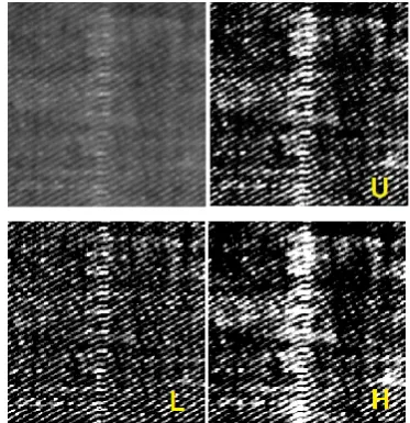
In the Figure 8, we can see on the left, the image of a missing pick, another quite common defect in fabrics. In the same image, we can see the result of the Retinex filtering. Again, using the same addition of images as previously proposed in the Figures 3 and 6, we can obtain the results given in the Figure 9.
Figure 8: The grey-tone image is showing a missing pick (image size is of 20mm). The other images (U, L and H) are those obtained using GIMP Retinex, for Uniform, Low and High levels. Note that the low level filtering is reducing the effect of the double pick, whereas the high level filtering is enhancing it.
Figure 9: Adding the High level filtered image to the inverse of the Low level filtered image from Figure 8 we obtain the image in the ( A ) panel. In the ( B ) panel, we can see the result given with a reduced number of grey tones. In panel ( C ) we can see the result after a suitable thresholding of the grey tones.
In these examples, we have considered an image of a certain fabric and from it, using the Retinex filter, we have obtained two images. One (L), which is obtained after selecting the low level filtering, is that where the lower intensity areas are evidenced. The other image, obtained using the high level (H), has the clearer areas which are favored. Let us note that, in the given examples, we have used a back lighting illumination system for inspecting the fabric. In them, we have seen a fault as a region which is transmitting more light. Therefore, L is close to the “good” fabric, H is close to the “bad” fabric. Therefore, from a single image of the fabric, we had two filtered images that we can compare to determine the presence of a defect.
http://www.ijSciences.com
Volume 6
– March
2017 (03
)
110
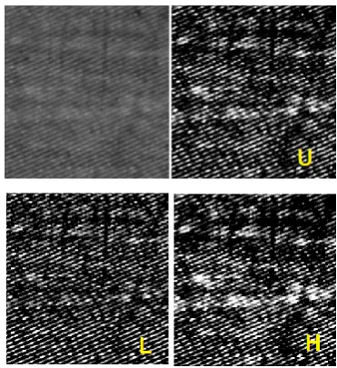
result after enhancing the contrast. In this example, the defect is stopping the light, but also in this case, the proposed approach based on L and H filtered images seems giving some interesting results.
Figure 10a: A weaving mismatch in a fabric. This defect has an extension on 8-10 yarns and, sometimes, it is difficult to identify. The size of the figure is 20 mm.
Figure 10b: Here the results of filtering the image 10a. On the left, we can see the image we obtain after mixing a Low and High filtered images as made in the previously proposed examples. In the right panel we can see the result after enhancing the contrast. Again, a segmentation of this image is easy to perform to identify the defect.
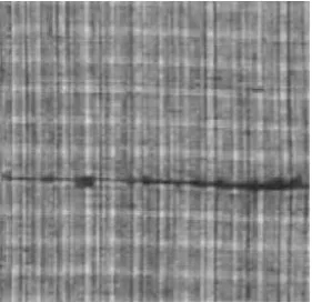
Another possible defect is that shown in the Figure 11a, where we see a fabric observed in front lighting. In the Figure 11b, we have the images we obtain after mixing L and H images. In the right panel, the result after thresholding. In fact, being the defect composed by bright yarns, for the Retinex filter it is the same as a region seen in back lighting which is transmitting more light.
Figure 11a: Defect in a complex fabrics with yarns of different colors (image size is 20 mm).
Figure 11b: Here the results of filtering the image 11a. On the left, we can see the image we obtain after mixing a Low and High filtered images as made for the example given in the Figure 3. In the right panel we see the result after enhancing the contrast.
Conclusion
As a conclusion, after the examples we have proposed in the previous images, we can tell that, from an image of a certain fabric, using the Retinex filter we can obtain at least two useful images. One can be that obtained after selecting the low level filtering (L), where we find the lower intensity areas of the image enhanced. The other image can be that obtained using the high level filter (H), where the clearer areas of the images are favored. If we suppose to work with a back lighting illumination system and that a fault is a part of the fabric which is transmitting more light, the proposed approach seems quite good. This happens because L is close to the “good” fabric and H is close to the “bad” fabric. In this manner, we have from an image of the fabric, two filtered images that we can compare to determine the presence of a defect.
http://www.ijSciences.com
Volume 6
– March
2017 (03
)
111
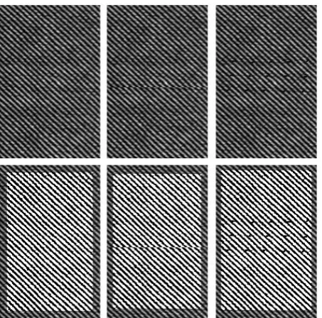
Figure 12: In the upper panels, the simulation of agood fabric (left) and the same with defects (middle, right). A simple Retinex filtering is evidencing their visibility.
Let us end the article with a further example of a simple use of GIMP Retinex. In the previous examples we have proposed this filter for preprocessing the images to be used in an automatic vision system. However, GIMP Retinex can be used to help the direct human vision, for instance in detecting tiny flaws of the fabric.
A simulation is given in the Figure 12. In the upper panel we have the fabric as it could be seen in a direct inspection: the defects are hardly visible. However a simple filtering with GIMP Retinex gives us the presence of defects. Then, a device which is giving a filtered image could be used to improve the visual inspection on the off-line stations.
References
1. Kumar, A. (2008). Computer-Vision-Based Fabric Defect Detection: A Survey, IEEE Transactions on Industrial Electronics, 55(1), 348-363. DOI: 10.1109/TIE.1930.896476 2. Rosandich, R. G. (1997). Intelligent Visual Inspection. London,
U.K., Chapman & Hall. ISBN: 9781461312017
3. Nickolay, B. N., & Schmalfuß, H. (1993). Automatic fabric inspection—Utopia or reality? Melliand-Text.ber., 73, 33–37. 4. Dockery, A. (2001). Automated fabric inspection: assessing the
current state of the art. Available at the site Techexchange.com 5. Jing, J., Zhang, H. , Wang, J., Li, P., & Jia, J. (2013). Fabric
defect detection using Gabor filters and defect classification based on LBP and Tamura method. Journal of the Textile Institute, 104(1), 18-27. DOI: 10.1080/00405000.2012.692940 6. Schneider, D., Holtermann, T., & Merhof, D. (2014). A
traverse inspection system for high precision visual on-loom fabric defect detection. Machine vision and applications, 25(6), 1585-1599.DOI: 10.1007/s00138-014-0600-y
7. Bhangale, R. S., & Zope, C. D. (2014). An Introduction to Textile Defect Identification and Classification Using Wavelet Transform and Neural Networks. International Journal of Advanced Electronics and Communication Systems.
Proceedings of the Int. Conference on Modeling and Simulation in Engineering & Technology (ICMSET-2014), 15th - 16th February 2014.
8. Li, P., Zhao, Z., Zhang, L., Zhang, H., & Jing, J. (2015). The Real-Time Vision System for Fabric Defect Detection with Combined Approach. In International Conference on Image and Graphics (pp. 460-473). Lecture Notes in Computer Science. Springer International Publishing. DOI: 10.1007/978-3-319-21969-1_41
9. Huang, C. P. (2014). A Study on the Algorithm of Fault Information Automatic Detection for High-Precision Intelligent Instruments. Advanced Materials Research, 846, 167-171. DOI: 10.4028/www.scientific.net/amr.846-847.167
10. Jinlian Hu (2011). Computer Technology for Textiles and Apparel, Elsevier. ISBN: 9781845697297
11. Sari-Sarraf, H., & Goddard, J. S. (1999). Vision systems for on-loom fabric inspection, IEEE Trans. Industry applications, 35, 1252-1259. DOI: 10.1109/28.806035
12. Campbell, J. G., & Murtagh, F. (1998). Automatic vision inspection of woven textiles using a two-stage defect detector, Opt. Eng. 37, 2536-2542. DOI: 10.1117/1.601692
13. Yau, H. F., Chen, P. W., Wang, N. C., & Lay, Y. L. (1998). Optimization of the illumination beam size of an optical textile defect inspection system, Meas. Sci. Technol. 9, 960-966. DOI: /10.1088/0957-0233/9/6/013
14. Ribolzi, S., Merckle, J., Gresser, J., & Exbrayat, P. E. (1993). Real time fault detection on textiles using opto-electronic
processing, Textile Res. J. 63, 61-71. DOI:
10.1177/004051759306300201
15. Kasdan, H. L. (1979). Industrial application of diffraction pattern sampling, Opt. Eng. 18, 496-503. DOI: 10.1117/12.7972419
16. Haralick, R. M., Shanmugam, K., & Dinstein, I. (1973). Textural features for image classification, IEEE Trans. Syst.,
Man, Cybern., SMC-3, 610-21. DOI:
10.1109/tsmc.1973.4309314
17. Abouelela, A., Abbas, I., El Deeb, I., & Nassar, S. (2000). A statistical approach for textile fault detection, IEEE International Conference on Systems, Man, and Cybernetics, 8-11 Oct. 2000, 4, 2857-2862. DOI: 10.8-1109/icsmc.2000.884431 18. Chan, C. H., & Pang, G. (2002). Fabric defect detection by
Fourier analysis, IEEE Transactions on Industry Applications, 36, 1267-1276. DOI: 10.1109/28.871274
19. Arivazhagan, S., Ganesan, L., & Bama, S. (2006). Fault segmentation in fabric images using Gabor wavelet transform. Machine Vision and Applications, 16(6), 356-363.
20. Kumar, A., & Pang, G. K. H. (2002). Defect detection in textured materials using Gabor filters, Industry Applications, IEEE Transactions on Industry Applications, 38, 425-440. DOI: 10.1109/28.993164
21. Jasper, J. W., Garnier, S. J. & Potlapalli, H. (1996). Texture characterization and defect detection using adaptive wavelets, Opt. Eng., 35, 3140-3149. DOI: 10.1117/1.601054
22. Montrucchio, B., Sparavigna, A., & Strigazzi, A. (1998). A new image processing method for enhancing the detection sensitivity of smooth transitions in liquid crystals, Liq. Cryst., 24, 841-852. DOI: /10.1080/026782998206669
23. Sparavigna, A. C., & Montrucchio, B. (2006). Performing Textile Fault Detection by Means of Texture Analysis. WSEAS Transactions on Signal Processing, 2, 541-548.
24. Sparavigna, A., & Montrucchio, B. (2006, April). Texture analysis for textile fault detection. In Proceedings of the 5th WSEAS international conference on Applied computer science (pp. 861-866). World Scientific and Engineering Academy and Society (WSEAS).
25. Sparavigna A., Dorma, G. & Montrucchio, B. (2006). Diffractive optics for fabric fault detection, pp. 82-88, Vol. 5, SCI2006 - X World Multi-Conference on Systemics, Cybernetics and Informatics, Orlando, Florida, July 16-19. 26. Sparavigna, A. C. (2015). GIMP Retinex for enhancing images
http://www.ijSciences.com
Volume 6
– March
2017 (03
)
112
27. Sparavigna, A. C., & Marazzato, R. (2015). Effects of GIMP Retinex Filtering Evaluated by the Image Entropy. arXiv preprint arXiv:1512.05653.
28. Marazzato, R., & Sparavigna, A. C. (2015). Retinex filtering of foggy images: generation of a bulk set with selection and ranking. arXiv preprint arXiv:1509.08715.
29. Sparavigna, A. C., & Marazzato, R. (2016). Evaluation of GIMP Retinex Filtering of Images by Means of the Shen++Max Shannon Entropy Finder. <hal-01308434> 30. Sparavigna, A. C. (2015). An image processing approach based
on Gnu Image Manipulation Program GIMP to the panoramic radiography. International Journal of Sciences, 4(5), 57-67. DOI: 10.18483/ijsci.721
31. Barnard, K., & Funt, B. (1999). Investigations into multi-scale Retinex, in Colour Imaging: Vision and Technology, L. MacDonald, Ed. and M. Ronnier Luo. Ed., John Wiley and Sons, pp. 9-17. ISBN: 9780471985310
32. Zhixi Bian, & Yan Zhang (2002). Retinex image enhancement techniques: Algorithm, application and advantages, EE264 final project report for Image Processing and Reconstruction. 33. Jobson, D.J., Rahman, Z., & Woodell, G.A. (1997). A
Multi-Scale Retinex for bridging the gap between colour images and
the human observation of scenes, IEEE Transactions on Image Processing 6(7):965-976. DOI: 10.1109/83.597272
34. Land, E.H. (1986). An alternative technique for the computation of the designator in the Retinex theory of color vision, Proc. Nat. Acad, Sci. 83:3078-3080. PMCID: PMC323455
35. Land, E.H. (1983). Recent advances in Retinex theory and some implications for cortical computations, Proc. Nat. Acad. Sci. 80:5163-5169. PMCID: PMC384211
36. Land, E. H. (1986). Recent advances in Retinex theory, Vis. Res. 26:7-21. DOI: 10.1016/0042-6989(86)90067-2
37. Land, E. H. (1959). Experiments in color vision, Scientific American, May Issue, 285-298.
38. Land, E. H. (1959). Color vision and the natural image, Proc. of the National Academy of Sciences 45(1):115–129. PMCID: PMC222521
39. Jobson, J., Rahman, Z., & Woodell, G.A. (1997). Properties and performance of a center/surround Retinex, Image Processing IEEE Transactions on 6(3):451-462. DOI: 10.1109/83.557356
40. Fabien Pelisson, GIMP Retinex,