http://www.sciencepublishinggroup.com/j/mcs doi: 10.11648/j.mcs.20190401.11
ISSN: 2575-6036 (Print); ISSN: 2575-6028 (Online)
LS Interference Alignment Algorithm Based on Symbol
Detection Assistance
Guoqing Jia
1, Junjun Du
1, Xuebin Zheng
21
College of Physics and Electronic Information, Qinghai Nationalities University, Xining, China
2Mechanical and Electrical Engineering, Hebei Normal University of Science & Technology, Qinghuangdao, China
Email address:
To cite this article:
Guoqing Jia, Junjun Du, Xuebin Zheng. LS Interference Alignment Algorithm Based on Symbol Detection Assistance. Mathematics and Computer Science. Vol. 4, No. 1, 2019, pp. 1-5. doi: 10.11648/j.mcs.20190401.11
Received: December 23, 2018; Accepted: January 14, 2019; Published: April 18, 2019
Abstract:
With the rapid growth of network users, how to increase the system capacity has become an urgent problem forthe current communication system in the case of limited spectrum resources. The introduction of multi-user systems has increased system capacity, but it has also led to inter-user interference, which has further affected system capacity. To solve the multi-user interference problem, interference alignment is introduced. Interference Alignment (IA) is an interference cancellation technique that effectively eliminates the effects of interfering signals by compressing the interfering signal into a space independent of the desired signal and then forcing the interfering signal to zero at the receiving end. However, in practical applications, interference-aligned transceivers require a joint design, which is often difficult to achieve. The traditional approach is to mathematically expect it, but it also leads to some degree of irrationality in the transceiver design. In this paper, based on the traditional least square interference alignment (LS-IA) algorithm, a symbol-detection-assisted least square interference alignment (SDA-LS-IA) algorithm is proposed for its shortcomings in transceiver algorithm design. Firstly, based on the precoding matrix and the zero-forcing matrix of the transceiver designed by the traditional LS-IA, the symbol detection is performed, and then the transceiver is designed again according to the detection symbol, and then the symbol detection is performed. The computer simulation proves that the proposed algorithm has better anti-interference performance than the traditional LS-IA.
Keywords:
Interference Alignment (IA), Interference Cancellation, Least Squares (LS), Symbol Detection Assistance1. Introduction
With the development of the global mobile market, the popularity of smart terminals and the development of the Internet of Things business, mobile data traffic has grown rapidly [1-3]. In response to this situation, interference alignment was first proposed by S. Jafar [4]. The main idea of IA is to precode the signal before it is sent, and then perform zero-forcing filtering after receiving the signal to separate the signal into two separate spaces, thus eliminating interference. It shows that the theoretical maximum degree of freedom of theK user interference channel can reach K / 2.
Suh C and Tse D firstly apply interference alignment to the cellular network and improve system freedom (DoF) by aligning the interfering signal with the subspace of the received signal [5]. An one-time linear precoding method is
proposed on a single time slot frequency to achieve optimal degrees of freedom [6]. But it requires a joint design of the transmitter and receiver, which is often difficult to implement in practice. At the same time, in non-ideal channel, complete freedom cannot be achieved. Aiming at this problem, based on different optimization criteria (eg, minimum interference to interference leakage (MIL), maximum signal to interference plus noise ratio (Max-SINR), least squares (LS) minimum mean square (MMSE)), a number of iterative transceivers have been proposed [7-8].
and symbolic detection joint iterative calculation algorithm. The proposed SDA-LS-IA algorithm has better performance than the traditional LS-IA by computer simulation.
2. Interference System Model for LS
Detection
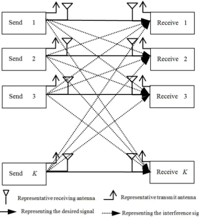
As shown in Figure 1, it is assumed that there are 2Knodes of symmetric users in a multiple-input multiple-output (MIMO) multi-user interference system [9-12], whereKis the transmitter and the other K nodes are receivers. In a wireless interference channel, each transmitter attempts to communicate only with the desired single receiver. Each transmitter carriesNtransmitting antennas, each receiver with
Mreceiving antennas, and the transmitter communicates with the desired receiver by transmitting d independent data streams.
Then the data received by theireceiver can be expressed as:
1 K
i i i i i i j j j i j= ≠j i
= , +
∑
, +,
y H V s H V s n (1)
1 CM i
×
∈
y represents the signal received by thei node, 1
CM×
represents the complex matrix of dimension M×1 , CM N i j
×
∈ ,
H
represents the channel matrix of the receiver transmitted from the transmitter of thejnode to the inode, and 1
CM i
×
∈
n represents the channel noise of the inode . Here, the model is constructed as an independent and identically distributed Gaussian matrix of zero mean and unit variance, that is, vec(Hi j,)∼N (C0 I, ) , N (C 0 I, )
represents a complex matrix with a mean of 0 and a variance of I, and Idenotes an unit matrix. CN d
j ×
∈
V is the transmission precoding matrix on the j transmitter, and 1
Cd
j ×
∈
s is the j transmitter transmission signal, which satisfies the condition E
( )
H =j j P s s I, P
represents power.
Figure 1. Multi-user system interference model.
Considering the zero-forcing of the received signal by the interference-forcing matrix in the receiver, the signal after zero-forcing can be expressed as
H H H H
1 =
K
i i i i i i i i i i j j j i i j= ≠j i
= , +
∑
, +,
ɶ
s U y U H V s U H V s U n (2)
i
U is specified as the interference-forcing matrix (combiner), so the ideal interference alignment condition can be inferred to be
(
H)
i i i i i
rank U H V, =d ∀i (3)
H
i i j, j= ∀ ≠j i
U H V 0 (4)
Where equation (3) guarantees that the desired signal can be demodulated, and equation (4) guarantees that the Interference signal can be completely eliminated.
According to the LS standard, a suitableUi can be solved
according to the following formula
2 H 1 2 H H H 1 1 i i K i i j j j i
j
K K
i i j j j i i i j j j i
j j = = = − − − ∑ ∑ ∑ , , , min min Tr ≜ U U
U H V s s
U H V s s U H V s s
(5)
Firstly, the matrix function U LS
f can be defined as follows
2 H 1 2 H H H 1 1
H H H H
1 1
H H H H H H
1 1
=
K U
LS i i j jj i j
K K
i i j jj i i i ll l i
j l
K K
i i j j j l l i l i j l
K K
i i j j j i i l l i l i i i
j l f = = = = = = = = − = − − − − + ∑ ∑ ∑ ∑∑ ∑ ∑ , , , , , , , Tr Tr
U H V s s
U H V s s U H V s s
U H V s s V H U
U H V s s s s V H U s s
(6)
Then, we can know k k
k k
∂TrAU =∂TrU A=
A
U U , so we can get the follow formula [8]
H H H H H H H
1 1 1
U K K K
LS
i i j j j l l i l i l l i l
i j l
i f = = = ∂ = − ∑∑ , , ∑ ,
U H V s s V H s s V H
U (7)
The best Ui is obtained, when 0 U LS i
f
∂ =
U is satisfied, that is,
H H H H H H H
1 1 1
1
H H H H H H H
1 1 1
H 1
H H H H H H
1 1 1
K K K
i i j jj l l i l i l l i l
j l l
K K K
i i l l i l i j j j l l i l
l j l
K K K
i i l l i l i j jj l l i l
l j l
i l = = = − = = = − = = = = = = = ∑∑ ∑ ∑ ∑∑ ∑ ∑∑ , , , , , , , , , ,
U H V s s V H s s V H
U s s V H H V s s V H
U s s V H H V s s V H
H
1
H H H H
1 1 1
K K K
l l j j i j i l l l i
j l l
−
= = =
∑∑ V s s V H, ∑H V s s,
(8)
Next, Vi is designed in the reverse link. Since the channels
are opposite, that is, the opposite channel satisfies H i l, = i l,
H H ,
by exchangingUi andVias the precoding matrix and the
zero-forcing matrix, the optimal precoding matrix Vi can be
1 H
H H H
1 1 1
K K K
i l i j i l
i l l j j l l i
j l l
− = = = = ∑∑ , , ∑ ,
V H U s s U H H U s s (9)
3. Algorithm Description
3.1. LS-IA Algorithm
The traditional LS considers that the design of the transceiver in the iterative calculation should not be related to the data stream [4, 8, 10]. In order to eliminate the influence of the data stream, the mathematically expected processing is performed on the data streamsjin the calculation of Ui and
i
V . In general, the symbol stream satisfies the following formula
( )
H( )
HEs sj j =PI, Es si j =0,i j≠ (10)
So we can get the best Ui and Viof formula (11-12)
1 H H 1
K
i i j j j i j i i i j − = =
∑
, , ,U H V V H H V (11)
1 H H 1
K
i j i j i i
i j j i
j − = =
∑
, , ,V H U U H H U (12)
In order to satisfy the ideal interference alignment condition of formula (3-4) in the traditional method,Vi is
firstly initialized to a random unitary matrix, and then equation (11) and formula (12) are iterated through the loop until the set iteration number is completed or some conditions are met. Finally,the data stream is detected passes through Ui and Vi, where Ui and Viis obtained by the above
steps. The definition algorithm is summarized as follows, where orth represents orthogonalization and Ui ⇐orth
{ }
Uirepresents orthogonalization of Ui ,the same applies
hereinafter.
Table 1. LS-IA algorithm.
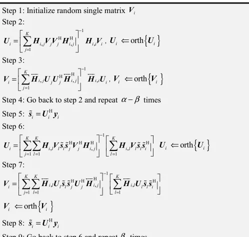
Step 1: Initialize random single matrix Vi Step 2:
1 H H 1
U H V V H, , H V,
K
i i j j j i j i i i j − = =
∑
, orth
{ }
i ⇐ i
U U Step 3: 1 H H 1 K
i j i j i i
i j j i
j − = =
∑
, , ,V H U U H H U , orth
{ }
i ⇐ i
V V
Step 4: Go back to step 2 and repeat α times
3.2. SDA-LS-IA Algorithm
In fact, the result of the formula (11-12) of the conventional method is the statistical result of the formula (8-9), which is expected to be superimposed on the data stream
j
s of the formula (8-9)[13]. So the two are not strictly equal,
especially if the data traffic is not large enough. This paper proposes an improved algorithm by making sj=sɶj as follows:
First, the precoding matrices Ui and Vi are iteratively
calculated using the traditional LS algorithm; then, the symbol detection is performed; finally, the iterative operation is performed again according to sj=sɶj , and Ui and Vi are
calculated.
So the best Ui and Vican be obtained as follows
1
H H H H
1 1 1
K K K
i i l l l j j i j i l l l i
j l l
− = = = =
∑∑
, , ∑
,ɶ ɶ ɶ ɶ
U H V s s V H H V s s (13)
1 H
H H H
1 1 1
K K K
i l i j i l
i l l j j l l i
j l l
− = = = =
∑∑
, ,∑
,ɶ ɶ ɶ ɶ
V H U s s U H H U s s (14)
Definingα andβ as iteration values. The algorithm is summarized as follows:
Table 2. SDA-LS-IA algorithm.
Step 1: Initialize random single matrix Vi Step 2:
1 H H 1
K
i i j j j i j i i i j − = =
∑
, , ,U H V V H H V, orth
{ }
i ⇐ i
U U Step 3: 1 H H 1 K
i j i j i i
i j j i
j − = =
∑
, , ,V H U U H H U, orth
{ }
i ⇐ i
V V
Step 4: Go back to step 2 and repeat α β− times
Step 5: sɶi=U yiH i Step 6:
1
H H H H
1 1 1
U H V s s V H, ɶ ɶ , H V s s, ɶ ɶ
K K K
i i l l l j j i j i l l l i
j l l
−
= = =
=
∑∑
∑
Ui ⇐orth{ }
UiStep 7:
1 H
H H H
1 1 1
K K K
i l i j i l
i l l j j l l i
j l l
− = = = =
∑∑
, ,∑
,ɶ ɶ ɶ ɶ
V H U s s U H H U s s
{ }
orth
i ⇐ i
V V
Step 8: H
i= i i
ɶ
s U y
Step 9: Go back to step 6 and repeatβ times
4. Simulation Results and Analysis
The performance of the proposed SDA-LS algorithm is simulated by computer, and the corresponding simulation parameters are set according to Table 3. The total number of iterations is set to 70, that is, α= 70.
Table 3. Simulation parameter settings.
The total number of iterations α 70
User number K 3
Transmitting antenna N 4
Receiving antenna M 4
Data stream d 2
Channel traversal times 100000
Modulation Mode QPSK
(13-14) (that is, SDA-LS-IA algorithm) is small or even no gain; when β is too large, due to the iterations number of equation (11-12) (that is, LS-IA algorithm ) is small, and the matrices Ui and Vido not converge, resulting in the
signal detected by equation (2) being substantially mismatched with the actual transmitted signal, that is to say ,the mean square error (MSE) and the bit error rate (BER) are large.
So the best β should be obtained by some special means and should change as the wireless parameters change.
Figures 2 and 3 are obtained with the SNR setting of 30 dB. Figure 2 shows the simulation results of the bit error rate (BER) under different β. Figure 3 shows the simulation results of the mean square error (MSE) at different β. It can be seen from Figure 2 that the BER reaches the lowest at β = 8; from Figure 3, it can be concluded that the MSE is also the lowest at
β = 8. Therefore, combining the two graphs shows that the performance of the algorithm is optimal when β = 8.
Figure 2. BER simulation results under different β.
Figure 3. MSE simulation results under different β.
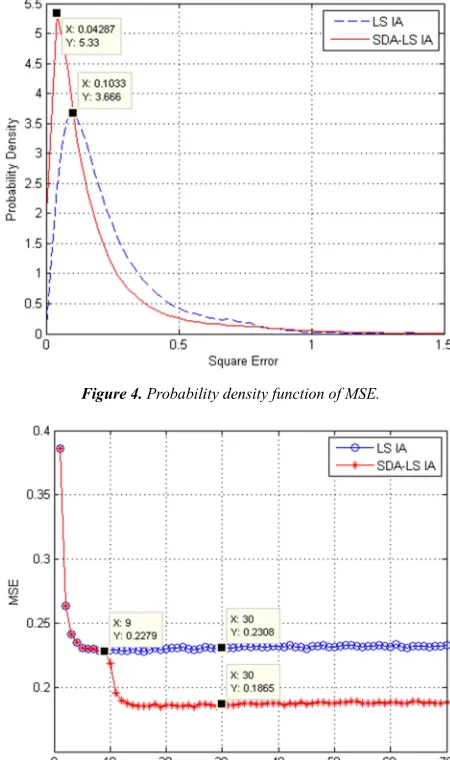
In accordance with Table 3, the relevant parameters are set, and Figure 4 and 5 are obtained through simulation. The horizontal axis of Figure 4 represents the variance of the algorithm, and the vertical axis of Figure 4 represents the probability density function (PDF) of MSE. It can be
seen from of Figure 4 that the simulation curve of the proposed algorithm is obviously left, that is, the probability of SDA-LS-IA is larger in the region with lower variance. Therefore, it can be concluded that SDA-LS-IA has significantly better MSE probability density performance than traditional LS-IA in the case where the precoder initialization matrix is the same.
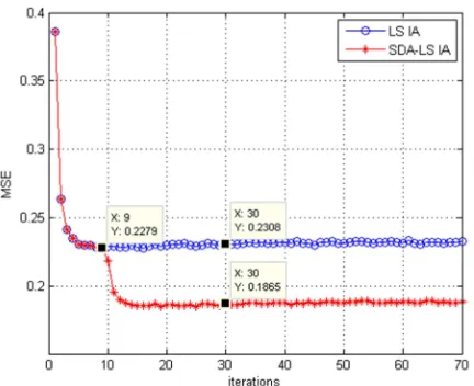
In addition, analysis of Figure 5 can lead to the conclusion that SDA-LS-IA exhibits consistent performance with LS-IA when the number of iterations is small; with the increasing of the number of iterations, SDA-LS-IA exhibits better MSE performance than traditional LS-IA.
Figure 4. Probability density function of MSE.
Figure 5. MSE comparison chart of SDA-LA-IA and LS-IA.
Figure 6. BER comparison of SDA-LS-IA and LS-IA.
5. Conclusion
Aiming at the shortcomings of traditional LS-IA algorithm in the transceiver design, this paper proposes a SDA-LS-IA iterative algorithm based on symbol detection assistance. From Figure 4, 5, and 6, we can see that as the number of iterations increases, the performance of both algorithms tends to be stable. SDA-LS-IA has better BER, MSE and PDF than LS-IA performance. So, the following conclusions can be drawn. Since the algorithm based on symbol detection is introduced on the basis of the traditional algorithm, the proposed detection algorithm shows better MSE and BER performance than the traditional algorithm.
Compared with LS-IA, SDA-LS-IA increases the number of iterations, which improves the performance of IA. In theory, performance improvement is large and the complexity is not improved much. Therefore, the proposed algorithm has research significance. The disadvantage of this paper is that there is no complexity analysis of the two algorithms.
Acknowledgements
This research is supported by the Key Laboratory of Wireless Sensor Network & Communication, Shanghai Institute of Microsystem and Information Technology, Chinese Academy of Sciences (grant 2016002).
References
[1] Anming Dong, Haixia Zhang, Dongfeng Yuan, Xiaotian Zhou. 2016. Interference Alignment Transceiver Design by Minimizing the Maximum Mean Square Error for MIMO Interfering Broadcast Channel. IEEE Transaction on Vehicular Technology. 65, 8 (August. 2016), 3024-6036.
[2] Galymzhan Nauryzbayev, Emad Alsusa. 2016. Enhanced Multiplexing Gain Using Interference Alignment Cancellation in Multi-cell MIMO Networks. IEEE Transaction on Information Technology. 62, 1 (January.2016), 357-369. [3] Zhiyu Cheng, Natasha Devroye, Tang Liu. 2016. The Degrees
of Freedom of Full-Duplex Bidirectional Interference Networks With and Without a MIMO Relay. IEEE Transaction on wireless Communications. 15, 4 (April.2016), 2912-2924. [4] Krishna Gomadam, Viveck R. Cadambe, Syed A. Jafar. 2011.
A Distributed Numerical Approach to Interference Alignment and Applications to Wireless Interference Networks. IEEE Transaction on Information Theory. 57, 6 (June. 2011), 3309-3322.
[5] Suh, C. and Tse, D. 2008. Interference Alignment for Cellular Networks [C]. 46th Annual Allerton Conference on Communications, Control and Computing (Illinois, USA, Sep. 2008).
[6] Vasilis N, Mohammad A, and Giuseppe C. Cellular Interference Alignment. IEEE Trans. Inf. Theory. 2015, 61(3), 1194-1217.
[7] K. Gomadam, V. R. Cadambe, and S. A. Jafar. A distributed numerical approach to interference alignment and applications to wireless interference networks. IEEE Trans. Inf. Theory. 57, 6 (Jun. 2011), 3309-3322.
[8] Razavi S M, and Ratnarajah T. Adaptive LS and MMSE based beamformer design for multiuser MIMO interference channels. IEEE Trans. Veh. Technol. 65, 1(2016), 132-144. [9] Hakjea Sung, Seok-Hwan, kyoung-Jae Lee. 2010. Linear
Precoder Designs for K-user Interference Channels. IEEE Transactions on Wireless Communications. 9, 1(January, 2010), 291-300.
[10] Paula Aquilina, Tharmalingam Ratnarajah. 2015. Performance Analysis of IA Techniques in the MIMO IBC With Imperfect CSI.IEEE Transaction on Communications. 63, 4 (April.2015), 1259-1268.
[11] Leonard H. Grokop, David N. C. Tse, Roy D. Yates. 2011.Interference Alignment for Line-of-sight Channels. IEEE Transactions on Information Theory. 57, 9 (September, 2011), 5820-5832.
[12] Cheuk Ting Li, Ayfer Ozgur.2016. Channel Diversity Needed for Vector Space Interference Alignment. IEEE Transactions on Information Theory. 62, 4 (April, 2016), 1942-1956. [13] Jia, G. Q., Pan, Y., Du, J. J., and Ji, X. H. 2018. Symbol