0 INTRODUCTION
Substantial improvements in energy efficiency in many industrial fields can be achieved by employing more effective heat transfer surfaces. The most effective heat transfer enhancement can be achieved by using fins as elements for heat transfer surface
area extension [1] and [2]. Kraus et al. [3] have
offered a detailed discussion of the mathematical models related to the optimization of finned systems with various profiles, such as rectangular, triangular,
etc. Mokheimer [4] has analysed the efficiency of
the fins for the constant and variable heat transfer coefficient for various profiles depending on the local temperature. The results have shown that the assumption of constant heat transfer coefficient through fins, results in a considerable underestimation of the fin efficiency.
Pardeep et al. [5] have estimated the heat flux
of a cylindrical heat exchanger with a system of rectangular and triangular fins and the comparison of temperature surfaces was carried out depending on the length of the fins. Moitsheki et al. [6] have developed a model that describes the profile of the temperature of one longitudinal fin with various profiles, as well
as the effects of thermal gradient conductivity, thermal conduction, and the coefficient of heat transfer.
Toner and Kilic [7] have numerically analysed the
temperature and the efficiency of rectangular and triangular fins, and the optimal dimensions have been calculated as a function of the Biot number.
Lindstedt and Kaj [8] have analysed analytically
and numerically the thermal performance for some shapes of fins, such as rectangular, triangular and trapezoidal, and the comparisons between fins have been presented. A particularly interesting model related to the optimization of finned surfaces through so-called thermal transmitting matrix was presented by Arthur [9]. In the work of Farzaneh et al. [10], a multi-objective optimization model is presented. By using the genetic algorithm, the optimization of geometrical parameters of the fins was done for
six various profiles. Taler and Duda [11] and Taler
[12] have presented two-dimensional temperature
distribution with analytical solutions for various
profiles. Rek et al. [13] have used CFD simulation to
analyse a heating oven, since the CFD is a common numerical technique, which is applied in many
simulations in different research studies. Bonefačić et
al. [14] have applied CFD software for modelling of
Thermal Optimization and Comparison of Geometric Parameters
of Rectangular and Triangular Fins with Constant Surfacing
Bunjaku, F. – Filkoski, R.V. – Sahiti, N.
Florent Bunjaku1 – Risto V. Filkoski2 – Naser Sahiti3,*
1 University of Prishtina “Hasan Prishtina”, Faculty of Education, Kosova 2 University “Sts Cyril and Methodius”, Faculty of Mechanical Engineering, Macedonia 3 University of Prishtina “Hasan Prishtina”, Faculty of Mechanical Engineering, Kosova
This paper presents an optimization model of fins of rectangular and triangular profiles, based on a constant value of the transverse cutting surface, as well as the optimization of the ratio of efficiency of both fin profiles. The optimization model is based on the analytical and numerical simulation of the heat flux through fins in order to derive relevant thermo-physical parameters of the investigated fin profiles. The optimization of both fin profiles is carried out for different fin materials based on constant heat transfer coefficient and for different fin materials based on variable heat flux. The efficiency of fins as relevant fin goodness parameter is also analysed and the optimal values of the ratio of fin efficiency of both profiles is graphically presented and the optimal value estimated. Numerical simulation of fin models is carried out by using ANSYS/Fluent software.
Keywords: fins, heat flux, optimisation, geometrical parameters, rectangular and triangular profile, fin efficiency
Highlights
• This paper presents an analytical and numerical analysis of heat transfer through finned heat exchanging surfaces. • The model of optimisation of the finned systems is based on the determination of optimal dimensions of fin profile related to
maximal values of heat flux through fins.
• Optimal fin thickness corresponding to the maximal heat flux as function of fin conductivity and heat transfer coefficient are presented.
• Examples of temperature fields of rectangular and triangular fins are presented.
an empty room without internal heat sources, with the aim of predicting heat balance and thermal comfort parameters. The study of Raisi [15] investigates natural convection cooling of a heat source that produces uniform heat flux, placed on the bottom of a cavity, filled with non-Newtonian power-law fluid. Filkoski et al. [16] have presented several case studies of analysis of different thermal systems with the application of the CFD technique, emphasizing its potential for research and for engineering educational purposes, which is demonstrated with practical examples and interpretation of test results in connection with certain specific issues.
The current paper provides an optimization of cross cutting geometry of rectangular and triangular fin forms in order to find the optimal geometry related to maximal heat flux. The optimization is based on analytical and numerical analysis based on CFD code ANSYS/Fluent and corresponding results are presented in tables and figures. The optimization is carried out for different fin materials and different heat transfer coefficient for both fin types. Further, the authors provided an optimization of the ratio of fin efficiency of both fin profiles as a function of fin
characteristic parameter N. To the best knowledge
of the authors, analysis of various aspects of fins in the literature has been carried out in an essentially analytical way.
1 COMPUTATIONAL MESH AND SIMULATION PROCEDURE
For the current computational model, a fine structured grid was created with elements numbering between 4005 and 6732 for the rectangular fins, and between 3298 and 4094 for triangular fins. As a solution method, the SIMPLE algorithm for velocity-pressure coupling was employed. The pressure field was discretized with a second order scheme whereas for the velocity and temperature field the second order upwind discretization scheme was applied. The convergence criteria for residuals of continuity and
momentum equations was set to 10-6 and 10-8 for the
energy equation.
2 OPTIMIZATION MODEL FOR RECTANGULAR FINS
The primary issue concerning the effectiveness of the heat exchangers is the methodology of intensifying the heat transfer, which would lead to optimal heat exchanger design.
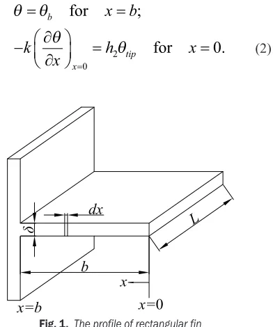
The differential equation that describes the phenomenon of heat transfer through fins (Fig. 1) is given in the following form:
d
dx m
2
2 2
0
θ θ
− = , (1)
where θ = T – Tfluid is the temperature difference
between the temperature of fins’ surface (T) and the
temperature of the surrounding air (Tfluid),
m= 2 /h kδ the characteristic finned parameter, h
the heat transfer coefficient and k the thermal
conductivity of the fin material.
The boundary conditions of the problem are:
θ θ
θ
θ
=
=
−
∂
∂
=
=
=
b
x tip
x b
k
x
h
x
for
for
;
.
02
0
(2)Fig. 1. The profile of rectangular fin
With θb is given the temperature difference at the base of the fin; h2 and θtip respectively are the heat transfer coefficient and the temperature difference at the top of the fin.
By considering the boundary conditions in Eq. (2) and taking h2 = 0 for simplifying the problem, i.e. the thermal flux at the top of the fin is neglected, the solution of the differential equation, Eq. (1), based on
[3], is obtained in this form:
θ( ) θ cosh
cosh ,
x mx
mb b
= (3)
Q k S d
dx x k mL b mb
0
0
= − ⋅
= =
θ δ θ
tanh( ). (4)
By replacing b and m in Eq. (4), the following is obtained:
Q0 A B
1 2 3 2 = ⋅δ / ⋅
(
⋅δ−/)
tanh , (5)
A L h k B S h k b
=θ 2 ⋅ ; = 2 . (6)
According to the adopted optimisation model,
for (dQ0/dδ) = 0, based on [17], the following
transcendental equation is obtained:
tanh
( )
u −3u+3u⋅tanh2( )
u =0, (7)where u=Bδ–3/2.
The solution of Eq. (7) is uopt = 1.419, and for the
optimal thickness and height of a rectangular fin the following applies:
δopt S h opt
k b
S k h
,
/
,
/
; .
=
⋅
= ⋅
2 1 3 1 3
(8)
In the following, the optimisation of the considered finned system is implemented, by adopting the surface of transversal cutting of the fin (S = δb) as a constant value, and by simulating corresponding values of the heat flux through fins of for various materials (steel, aluminium and copper) and various ratios of δ and b. The results for heat flux are presented in terms of fin thickness δ (Fig. 2).
Fig. 2. Heat flux through rectangular fins as function of the fin conductivity (k) and fin thickness (δ)
From the diagram in Fig. 2, it can be noted that the generated heat flux increases at the beginning, up to a maximal value and later it decreases, by increasing the thickness of the fin (δ). Furthermore, the diagram shows that for all three types of fin materials (steel, aluminium, copper) the optimal thickness of the fin profile can be identified. Regarding the graph in Fig. 2, it should be noted that maximal values for heat flux in Figs. 2 and 7 are related to a trade-off between the convective heat transfer area and fin efficiency. It should also be noted that for constant fin length
(L) convective heat transfer area for particular fin
geometry depends only on fin thickness (fin height b)
whereas fin efficiency depends on fin thickness but also on fin material. While increasing of fin efficiency with increasing of fin thickness (reducing fin height) for copper is faster for low values and, in that way, reaches faster an apparently constant value, increasing of fin efficiency over fin thickness for steel is slower. This means that in the case of copper fins, benefits related to increasing fin efficiency with increasing fin thickness diminishes faster due to reducing of convective heat transfer area, and this means that the maximal value of heat transfer flux is faster achieved for fins of cupper material compared with fins of materials with lower conductivity (aluminium, steel)
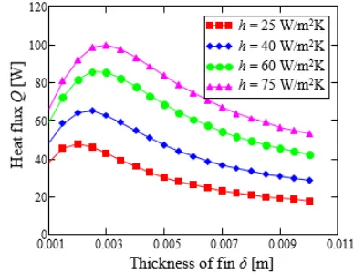
A further analysis performed in the present work is on identifying the optimal thickness of the fin as a function of the heat transfer coefficient (Fig. 3). In this case, the subject of analysis is only the aluminium finned heat transfer surface, given that the analysis would be the same for other types of materials.
Fig. 3. Heat flux through rectangular fins as function of thickness
(δ) for the Aluminium material
From Fig. 3, it can be noted that for the same
value of the fin thickness (δ) for fins characterized
with a higher convection heat transfer coefficient (h), higher values for the heat flux are obtained.
The efficiency of the finned surface is defined as the ratio between the actual heat flux and heat flux that could be ideally obtained. For the rectangular fin, the efficiency is determined according to the following expression:
η δθ
θ
=Q = =
Q
km mb
hb
N N re
id
b
b
tanh( ) tanh( )
, (9)
where N mb= = 2 /h k bδ⋅ is the characteristic
Values obtained by numerical simulations and analytical values for various materials are presented in Table 1 and Fig. 4.
Table 1. Analytical and numerical values for rectangular fins Rect. Steel
k = 16.27 W/(mK)
h = 25 W/(m2K)
Aluminium
k = 202.4 W/(mK)
h = 25 W/(m2K)
Copper
k = 387.6 W/(mK)
h = 25 W/(m2K)
Q [W] Q [W] Q [W] No Fins’ dim.
[mm] Anal. Num Anal. Num Anal. Num 1 1 x 250 10.82 10.80 38.15 38.22 52.47 52.59 2 1.75 x 143 14.32 14.34 47.29 47.53 58.96 59.34 3 2 x 125 15.31 15.35 47.80 48.11 57.27 57.70 4 2.5 x 100 17.09 17.16 46.13 46.56 51.91 52.44 5 5 x 50 20.87 21.17 30.14 30.82 30.77 31.48 6 7.5 x 33.4 18.84 19.35 21.92 22.68 22.08 22.85 7 10 x 25 16.51 17.09 17.87 18.60 17.93 18.67
Fig. 4. Comparison of analytical and numerical results for heat flux for various materials of rectangular fins
From Fig. 4 it is obvious that a better results agreement is achieved for fins with smaller thicknesses, whereas with increasing of fin thickness the results agreement is lower. This is because for the analytical solution the problem is considered to be one dimensional whereas a three-dimensional model is applied for the numerical solution.
Fig. 5. Numerical prediction of temperature profile of rectangular fin of the Al material by taking the constant surface S = 0.00025 m2
Fig. 5 presents a temperature profile of an Al rectangular fin, carried out by means of ANSYS/ Fluent software. Similar temperature profiles were obtained in the other cases that are presented in Table 1. The simulation for other materials (steel and copper) is done in the same way, and the results are presented in Table 1.
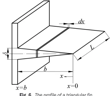
3 OPTIMIZATION MODEL FOR TRIANGULAR FINS
We the triangular fins, we deal with changeable fin profile (Fig. 6). In the current analysis, the fin temperature gradient change in the orthogonal direction of the transversal cut is neglected, meaning that a one-dimensional temperature field within the fin profile is analysed.
Fig. 6. The profile of a triangular fin
The differential equation describing the heat transfer through triangular fins, is given in the following form:
x d dx
d dx m b
2
2
2
0
θ + θ − θ=
, (10)
where the characteristic finned parameter (m) is
defined according to [3], while b is the fin height. The boundary conditions that apply are:
θ θ θ
= =
− ∂
∂
= =
= b
x
x b
k
x x
for
for ,
.
0
0 0 (11)
Eq. (10), is a modified Bessel differential equation which solution is:
θ =C I m bx C K m bx1 0(2 )+ 2 0(2 ), (12)
where I m bx0(2 ) is a modified function of the first
while K m bx0(2 ) is a modified function of the
second type, of the sequence 0 and with modulation
2m bx.
Integration constants C1 and C2 are determined as per boundary conditions:
for is
for is
x d
dx
x b b
= =
= =
0 θ 0
θ θ
,
. (13)
The first boundary condition means that the thermal flux at the top of the trapezoidal fin can be ignored, while the second boundary condition shows that the temperature difference at the base of the fin is equal to θb.
By replacement of values of constants C1 and C2
in Eq. (12) following form of the expression for the temperature field of the triangular fin is obtained:
θ( ) θ ( )
( ) .
x I m bx I mb
b
= 0
0
2
2 (14)
The heat flux through triangular fin may be expressed by:
Q k S d dx
hL I mb m I mb
x b
b
= ⋅
= ⋅ ⋅ =
θ 2 θ 2
2
1
0
( )
( ) . (15)
The optimal thickness of trangular fin is estimated based on methodology similar to that used for rectangular fins. The surface of transverse cutting of the fin is S = δb/2 and by replacing the fin height
b = 2S/δ in Eq. (15), the following expression is
obtained:
Q A I B
I B
= ⋅ ⋅ ⋅
⋅ − −
δ δ
δ
1 2 1
3 2
0
3 2 /
/
/
( )
( ), (16)
where:
A L= ⋅θb 2hk; B=4S h k2 / . (17) According to the adopted optimisation model, for (dQ0 / dδ) = 0 based on [17], following transcendental equation is obtained:
4I u I u1( )⋅ 0( )−3uI u02( )+3uI u12( )=0. (18)
By solving this equation, the optimal value of the variable u is found to be uopt=2.619.
Hence, following optimal dimensions of the triangular fin are obtained:
δopt S h opt
k b
S k h ,
/ ,
/
. ; . .
∆ = ⋅ ∆
= ⋅
1 671 1 197
2 1 3 1 3
(19)
In the following, similarly to the previously presented optimization model of the rectangular fins,
the triangular fin model is implemented by adopting the fin profile surface S = δb/2, as a constant surface, by simulating respective values of the heat flux for various materials (steel, aluminium, copper).
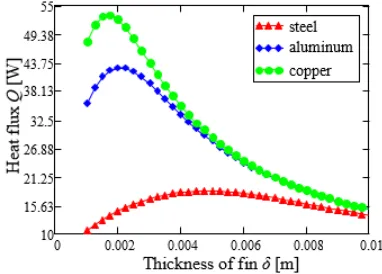
As in the case of the respective rectangular models, it can be noted that, by increasing the fin thickness (δ), the heat flux through fins is increased up to a maximal value and then it is decreased, Fig. 7. Further, the graphical presentation of the behaviour of heat flux for all three types of materials shows that in all the cases, the optimal fin thickness can be clearly identified.
Again, in similarity to analyses of rectangular fin profile, the optimal triangular fin thickness is presented as a function of the heat transfer coefficient (Fig. 8). In the corresponding case, the results only for Al fins are presented, since the analyses of finned surfaces made from other materials can be performed in the same way.
Fig. 7. Heat flux through triangular fins as function of the fin conductivity (k) and fin thickness (δ)
Fig. 8. Heat flux through triangular fins as function of thickness (δ)
Table 2. Analytical and numerical values for triangular fin
Tria.
Steel
k = 16.27 W/(mK)
h = 25 W/(m2K)
Aluminium
k = 202.4 W/(mK)
h = 25 W/(m2K)
Copper
k = 387.6 W/(mK)
h = 25 W/(m2K)
Q [W] Q [W] Q [W] NoFins’ dim. [mm] Anal. Num. Anal. Num. Anal. Num.
1 2x125 14.47 14.49 42.77 42.96 52.23 52.46 2 2.5x100 15.84 15.87 42.00 42.24 48.45 48.74 3 5x50 18.46 18.67 28.29 28.66 29.07 29.46 4 7.5x33.4 16.50 16.90 19.64 20.16 19.81 20.34 5 10x25 13.72 14.29 14.89 15.54 14.94 15.59
Fig. 9. Comparison of analytical and numerical results for heat flux for various materials of triangular fins
The same explanation regarding matching of values obtained analytically and numerically, provided in relation to Fig. 4, is valid also for Fig. 9.
The temperature profile resulting from the heat flux transferred through the Aluminium fins, by changing the geometrical parameters of the fin profile, but by keeping the transversal surface of the fin constant, is presented in Fig. 10. The same methodology is completely applicable for analysis of fins of other materials presented in Table 2 and Fig. 9.
Fig. 10 presents the temperature field obtained from numerical simulation by application of the programme ANSYS/Fluent for the Aluminium fin models, as for the conditions given in Table 2. The results obtained with the CFD simulations of the finned surfaces of other materials are similar and in the frame of the expectations.
The efficiency of the finned heat exchanging surface with triangular fin profile is given with the following relation:
η = 1 ⋅ 2
2
1
0
N I N I N
( )
( ). (20)
Fig. 10. Numerical presentation of temperature field in triangular fin for Aluminium material by taking
the constant surface S = 0.000125 m2
4 OPTIMIZATION OF THE RATIO OF EFFICIENCY OF TRIANGULAR AND RECTANGULAR FIN PROFILES
From Eq. (9) and (20), the expression for the ratio of efficiency of triangular and rectangular fin profiles is derived as:
η
η∆ = ⋅
1 2
2
1
0
tanh( )
( )
( ).
N
I N
I N (21)
Minimal value of the mentioned ratio is determined according to the following relation:
d
dN
N I N I N I N
N
N I N
η η∆
=tanh( ) ( )( ( )−
( )
) tanh ( ) (
0 0
1
2 0 2
2 2 2 2
2 ))
( ) ( tanh ( )) ( ) tanh( ) ( )
tanh ( ) (
−
− +
I N N I N N I N
N I
1
2
0 1
2 0 2
2 1 2 2 2
2
2N) =0. (22)
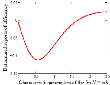
The extreme point of this ratio depending on the
characteristic finned parameter N is determined via
the graphical solution of the transcendental Eq. (22).
Fig. 11 shows that for the value N = 1.701, the first
derivate of this ratio is equal to zero.
Fig. 11. Graphical solution of the transcendental Eq. (22)
η η∆
= =
min
. . .
0 89 for N 1 701 (23)
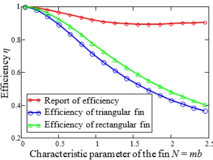
The graphical presentation of efficiencies of rectangular and triangular fin profiles, as well as the ratio of both efficiencies, is provided in Fig. 2.
Fig. 12. Comparison of the fin efficiency of analysed fins
From Fig. 12, it can be noted that the efficiency of rectangular fins is higher than the efficiency of the triangular fins, but from the view point of the heat flux transfer and the compactness of the design the triangular fin profiles are more favourable.
5 CONCLUSIONS
This paper provides the results of optimization of the heat transfer rate of rectangular and triangular fin profiles, in terms of estimation of the optimal fin thickness and fin height. The optimization of geometrical parameters of the finned heat exchanging surfaces for various fin models is carried out by taking constant values of the surface of transversal cutting of the fins, respectively of the volume of fins of various materials. For both fins of rectangular and triangular profiles analysed, and for different fin materials, optimal thickness and height are identified, respectively.
Optimal fin thickness for various fin models and materials (steel, aluminium and copper) is presented in tables and figures. It may be concluded that for optimal thickness of the fins, the heat flux through rectangular fins is higher for 11 % to 13 % compared to that through triangular fins, depending on the fin material, while the volume of rectangular fins is two times larger than the volume of the triangular fins. This means that the major part of heat flux is transferred from the fin part close to fins base since
the influence of the fin convection area fare from the fin base is less effective.
The current optimisation model based on
adaption of S = const., respectively the comparison
of Eq. (8) and Eq. (19) indicates that the ratio of optimal thickness of the analysed fin profiles is (δopt,Δ/δopt,□) = 1.671, while the ratio of optimal
fin heights is (bopt,Δ/bopt,□) = 1.197. The optimal
geometrical parameters of the fins determined here might serve as a practical tool for engineers involved in designing of fined heat transfer surfaces.
In the current paper, it is also shown that the ratio of the efficiency of triangular and rectangular fins reaches a minimal value for a certain value of the characteristic parameter of the finned N.
Finally, it may be concluded that both optimisation models are very important because they can be used to estimate the optimal geometry of fin profiles, which would result in the highest heat flux through fins for a given fin volume, given fin material expenditure.
6 NOMENCLATURES
h heat transfer coefficient, [W/(m2K)]
b fin height, [m]
I modified Bessel function of the first kind
k thermal conductivity, [W/(mK)]
L fin length, [m]
m fin performance parameter, [m−1]
N characteristic parameters of the fin
S cross-sectional or profile area, [m2]
T temperature, [K]
Greek symbols
δ fin thickness, [m]
θ temperature difference [K]
φ fin effectiveness
η fin efficiency
Subscripts
b base of fin
fluid surrounding air
re real
id ideal
Δ triangle form □ rectangular form
7 REFERENCES
[2] Sahiti, N., Bunjaku, F., Krasniqi, D. (2013). Assessment of single phase convection heat transfer enhancement. Journal of Trends and the Development of Machinery and Associated Technology, vol. 17, no. 1, p. 133-136.
[3] Kraus, A., Aziz, A., Welty, J. (2002). Extended Surface Heat Transfer. John Wiley & Sons, New York.
[4] Mokheimer, E.M. (2003). Heat transfer from extended surfaces subject to variable heat transfer coefficient. Heat and Mass Transfer, vol. 39, no. 2, p. 131-138, DOI:10.1007/ s00231-002-0338-3.
[5] Pardeep, S., Harvinder, l., Baljit Singh, U. (2014). Design and Analysis for Heat Transfer through Fin with Extensions. International Journal of Innovative Research in Science, Engineering and Technology, vol. 3, no. 5, p. 12054-12061. [6] Moitsheki, R.J., Rashidi, M.M., Basiriparsa, A. (2015). Analytical
solution and numerical simulation for one-dimensional steady nonlinear heat conduction in a longitudinal radial fin with various profiles. Heat Transfer—Asian Research, vol. 44, no. 1, p. 20-38, DOI:10.1002/htj.21104.
[7] Toner, M., Kilic, A. Onat, K. (1983). Comparison of rectangular and triangular fins when condensation occurs. Wärme - und Stoffübertragung, vol. 17, no. 2, p. 65-72, DOI:10.1007/ BF01007220.
[8] Lindstedt, M., Lampio, K., Karvinen, R. (2015). Optimal shapes of straight fins and finned heat sinks. Journal of Heat Transfer, vol. 137, no. 6, p. 061006, DOI:10.1115/1.4029854. [9] Snider, A.D.S. (1982). Mathematical techniques in extended
surface analysis. Mathematical Modelling, vol. 3, no. 3, p. 191-206, DOI:10.1016/0270-0255(82)90024-0.
[10] Farzaneh Hajabdollahi, F., Rafsanjani, H.H.. Hajabdollahi, Z., Hamidi, Y. (2012). Multi-objective optimization of pin fin to
determine the optimal fin geometry using genetic algorithm. Applied Mathematical Modelling, vol. 36, no. 1, p. 244-254, DOI:10.1016/j.apm.2011.05.048.
[11] Taler, J., Duda, P. (2006). Solving Direct and Inverse Heat Conduction Problems. Springer, Berlin, DOI:10.1007/978-3-540-33471-2.
[12] Taler, D. (2014). Fins of straight and circular geometry, Encyclopedia of Thermal Stresses, (Hetnarski, R.B., ed), Springer, Dordrecht, p. 1670-1683, DOI:10.1007/978-94-007-2739-7_383.
[13] Rek, Z., Rudolf, M., Zun, I. (2012). Application of CFD simulation in the development of a new generation heating oven. Strojniški vestnik - Journal of Mechanical Engineering, vol. 58, no. 2, 134-144, DOI:10.5545/sv-jme.2011.163. [14] Bonefacić, I., Wolf, I., Franković, B. (2015). Numerical
modelling of thermal comfort conditions in an indoor space with solar radiation sources. Strojniški vestnik - Journal of Mechanical Engineering, vol. 61, no. 11, 641-650, DOI:10.5545/sv-jme.2015.2493.
[15] Raisi, A. (2016). Natural convection of non-Newtonian fluids in a square cavity with a localized heat source. Strojniški vestnik - Journal of Mechanical Engineering, vol. 62, no. 10, p. 553-564, DOI:10.5545/sv-jme.2015.3218.
[16] Filkoski, R.V., Chekerovska, M., Bunjaku, F. (2016). Research and education in thermal and power engineering with support of CFD technology. International Conference REMOO “Science and Engineering for Reliable Energy”.
[17] Milincic, D. (1989). Heat Transfer. Naučna