Development of single row automatic transplanting device for potted
vegetable seedlings
Xin Jin
1,2, Daoyi Li
3, Hao Ma
1, Jiangtao Ji
1,2*, Kaixuan Zhao
1, Jing Pang
1(1. College of Agricultural Equipment Engineering, Henan University of Science and Technology, Luoyang 471003, China;
2. Collaborative Innovation Center of Machinery Equipment Advanced Manufacturing of Henan Province, Luoyang 471003, China; 3. Chinese Academy of Agricultural Mechanization Sciences, Beijing 100083, China)
Abstract: In China, low degree of automation seriously affects the working efficiency and quality in vegetable transplanting. As one of the most important vegetables in China even in the world, tomato was taken as the research object in this study. An automatic single-row transplanting device was designed, based on the statistical analysis of the physical and mechanical properties of tomato seedlings of a typical variety. Based on the technology of mechatronics, the device integrated the functions of transporting seedling tray, automatic seedling extraction and mechanical planting. The kinematics orthogonality solution combined with the dynamic sequence solution method was used to optimize and analyze the kinematic parameters of the automatic seeding mechanism, and the “sickle” trajectory was obtained. According to the position and movement requirement for taking and dropping seedling, the mechanical conditions and the working parameters of key execution parts were obtained by using analytic drawing method to analyze the mechanical condition of seedling collecting mechanism. The transplanting experiment was conducted at room temperature of 25°C, and the age and moisture content of the seedlings were 40 d and 55%, respectively. The results showed that the highest success rate was 92.59%, and the lowest rate of leakage was 23.13%, when the transplanting frequency was 60 plants/min. The lowest success rate was 77.78%, and the highest rate of leakage was 38.75%, when transplanting frequency was 120 plants/min. When the transplanting frequency is between 60-90 plants/min, the device can meet the requirement of high speed transplanting for potted vegetable seedling.
Keywords: potted vegetable seedling, seedling mechanism, automatic transplanting, tomato seedling, transplanting experiment
DOI: 10.25165/j.ijabe.20181103.3969
Citation: Jin X, Li D Y, Ma H, Ji J T, Zhao K X, Pang J. Development of single row automatic transplanting device for potted vegetable seedlings. Int J Agric & Biol Eng, 2018; 11(3): 67–75.
1 Introduction
China has grown about 21 million hm2 of vegetables with a total production of 800 million tons, accounting for about 60% of the world's total vegetable production, and becomes the largest vegetable producer in the world[1]. Sixty percent (60%) of vegetables in China is cultivated by seedling transplant, such as tomatoes, capsicum, broccoli. At present, semi-automatic transplanting machines have also begun to be popularized and applied in China[2-5]. The typical models are 2ZY-2A hoisting cup transplanter and 2ZB-2 duck beak transplanting machine with planetary gear train produced by Modern Agricultural Equipment Co., Ltd. They are able to transplant vegetable seedlings with large plant spacing. The 2ZY-2 film transplanter produced by Qingzhou Hualong Machinery Technology Co., Ltd. and the 2ZQ-4 chain clip transplanter made by Fulaiwei Agricultural
Received date: 2017-11-12 Accepted date: 2018-03-01
Biographies: Xin Jin, PhD, Associate Professor, research interests: vegetable production mechanization, Email: [email protected]; Daoyi Li, PhD, Senior Engineer, research interests: mechanical properties of crops, Email: [email protected]; Hao Ma, PhD, Lecturer, research interests: agricultural automatic control system, Email: [email protected]; Kaixuan Zhao, PhD, Lecturer, research interests: agricultural information and intelligent machine, Email: [email protected]; Jing Pang, Master, Lecturer, research interests: farm machine and mechanical reliability, Email: [email protected].
*Corresponding author: Jiangtao Ji, PhD, Professor, research interests: production machinery for dryland farming. College of Agricultural Equipment Engineering, Henan University of Science and Technology, Luoyang 471003, China. Tel: +86-379-64877837, Email: [email protected].
Equipment Co., Ltd. are suitable for transplanting vegetable seedlings with small plant spacing. But the semi-automatic transplanter only realized the mechanical planting of seedling, the process of seedling picking and seedling feeding still needs to be completed manually, which is restricted by the fatigue limit of human being, and the transplanting speed is low (about 30- 40 plants/min).
pushing mechanism, a dividing mechanism and planting parts, etc. When it is working, the pushing mechanism pushes out the seedlings in the tray and fell them into the dividing mechanism. Then, the seedlings were fed into the guide tube and fell into the seedling groove to complete the transplanting of the potted vegetable seedlings. Automatic Seedling extraction Mechanism of Elliptic Planetary Gear Train, developed by Zhejiang University of Technology[9-15], is able to take the seedlings from tray and place them in the hole. Han et al.[16] developed an automatic transplanting machine for dry land. It is composed of a tray device, a seedling collecting device, a seedling feeding mechanism with square cups, and a seedling throwing mechanism. The seedling collecting device consists of a row of seedling collecting fingers. The seedling is taken by grabbing its stem and the seedling throwing mechanism uses a cup-type planter. The machine was improved on the basis of the semi-automatic transplanting machine, but because the seedling was taken by clamping, it was required that the diameter and toughness of the seedling stem are high. Chen et al.[17] and Wang et al.[18] built models to simulate the transfer and delivering system of seedling transplanting. The conveyor belt combined with the guide wheel was used to line up the potted seedlings, and pots splitting device with double pin and seedling dropping device with trigger tray were driven by cam disc. But the study did not address the problem to move the seedlings from the tray and place them on the conveyor belt.
Based on the previous research[19-27], an automatic device for vegetable transplanting was designed in this study. This device used robotic hand to pick up the seedling from holes in the tray and integrated the functions of horizontal and longitudinal seedling supply, precise seedling extraction and low loss planting. Automatic vegetable transplanting device with precision seedling and low loss planting function. The key parameters were optimized by motion and force analysis, and the operation performance was verified and analyzed.
2 Physical parameters of tomato seedling
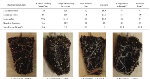
The variety of tomato seedlings applied in the test was Jinguan 19. A 128-hole tray was used to cultivate the seedlings, with a grid depth of 42 mm. The size of the upper hole was 30 mm × 30 mm, the bottom hole was 15 mm × 15 mm, and the volume of each grid was 21 mL. Seedling substrates were mainly composed of peat and perlite at a volume ratio of 2:1. The seedlings were cultivated at 16°C-25°C. The seedlings were 40 d old and moisture content was 55% to 60%. The moisture content was controlled within the range of 50% and 60%. DZG-6020 vacuum oven and AR1530 electronic balance were used to measure the moisture content of potted seedlings. Moisture content of potted seedling was measured by the dry and wet mass method, where the moisture was the ratio of the mass of dried seedling and the wet mass of it. The moisture contents of the seedlings in one tray were considered the same. Twenty seedlings in the same plane were randomly selected to measure the moisture of them, and the average value of them was used as the moisture content of the seedlings in this plane. In order to provide theoretical references for the design of key components of automatic transplanting device, 50 tomato seedling samples were randomly selected to measure the related physical parameters, and the results are shown in Table 1.
The pressure resistance of the seedlings is the ultimate pressure that the potted seedlings can withstand before it breaks and collapses. In the experiment it was found that the tomato seedlings with 55% moisture content had the highest compressive resistance and the maximum pressure resistance was 5.1 N, as shown in Figure 1. The adhesive force of the seedling is the friction between the lateral wall of the potted seedlings and the lateral wall of the hole. Therefore, in order to avoid damaging the potted seedling in the process of clamping the seedling, it is necessary to ensure that the potted seedling has higher compression resistance and the adhesion force is relatively small.
Table 1 Statistical results of tomato pot seedlings physical properties
Statistical parameters Width of seedling leaves/mm Height of seedling leaves/mm Stem diameter /mm Weight/g Compressive resistance/N Adhesive force/N
Maximum value 112 138 2.3 18.3 5.1 3.1
Minimum value 80 108 1.8 17.6 3.7 1.9
Mean value 99.2 121.8 2.1 17.9 4.2 2.7
Standard deviation 9.6 11.9 0.2 0.2 0.5 0.3
Variable coefficient/% 9.6 9.8 9.5 1.1 11.9 11.1
3 General scheme design of automatic transplanting
device
3.1 General structure
As shown in Figure 2, the designed automatic transplanting device for tomato seedlings is mainly composed of seedling collecting mechanism, seedling supplying mechanism, a duckbilled planting mechanism with eccentric-disk parallelogram, a seedling picking chain transmission, a planting chain transmission, a control system, a variable frequency motor and a body frame. The seedling supply mechanism is composed of horizontal and vertical tray-moving mechanisms. The horizontal tray-moving mechanism moves plug trays horizontally through the stepping motor driving a lead screw slideway. The vertical tray-moving mechanism moves the plug trays through a stepping motor driving a parallel double chain. There are four duckbilled planters in uniform arrangement on the planting mechanism. The seedling picking mechanism is composed of gears, a connecting rod and clamping claws. The control system is composed of a stepping motor, a position sensor and a programming controller.
3.2 Working principles
The working principles for automatic transplanting are shown
in Figure 3.
The device rotates the planting mechanism and seedling picking mechanism at a certain rotating speed through a variable frequency motor, and it is controlled by a planting chain transmission and a seedling picking chain transmission. The transmission ratio of the seedling picking chain was set to 1:4. During working, when the clamping claw reaches a lowest point, the planting device also reaches a highest point at the same time. After the clamping claw picks up the seedlings, the stepping motor drives the horizontal tray moving device to move the tray to the next grid hole. In the meantime, the clamping hand holds a seedling and moves to the lowest point when the planting mechanism ascends to the highest point, then the clamping claw drops the seedlings at the planting hole. Afterwards, the planting mechanism moves downwards to the lowest point to drop the seedlings and the clamping claw goes back to pick up the next seedling. This process is repeated and when the seedling picking mechanism picks up the last seedling in a row of grid holes, the stepping motor drives the vertical tray moving mechanism to move to the next row and picks up the first seedling in that row, and seedling picking and seedling planting starts again. The repeated action of the whole process can realize the automatic transplanting of vegetable seedlings with high efficiency.
1. Seedling picking cabinet 2. Seedling supply body frame 3. Variable frequency motor 4. Whole body frame 5. Seedling supply device 6. Seedling picking device 7. Seedling picking chain transmission 8. Planting device 9. Planting chain transmission 10. Planting control cabinet
Figure 2 Automatic transplanting device for potted tomato seedlings
a. Seedling supply b. Seedling picking c. Planting Figure 3 Working principles of the automatic transplanting device
4 Design of automatic seedling picking mechanism
4.1 Requirements for seedling extraction
The basic idea of taking the seedling from the pot with a
reduce of the work efficiency caused by human fatigue. Therefore, picking trajectory is required to meet the following conditions:
(1) An approximate straight line is needed in the trajectory to ensure that the seedling execution parts are less agitated in the bowl;
(2) The trajectory needs to have a certain height to ensure that the seedling pot does not interfere with other objects in the stage of moving and throwing seedlings;
(3) The angle between the trajectory segment of seedling taking and dropping in descending stage should not be limited to avoid increasing the working time.
Therefore, this paper proposed a “sickle” type seedling track to achieve high efficiency and low loss of seedling taking and dropping.
4.2 Structure and working principle of seedlingmechanism
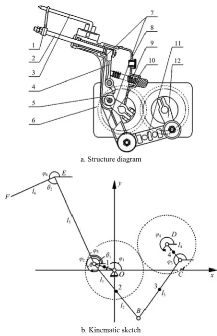
In order to meet the requirement of “sickle” type seedling track, a new type of rotating automatic seedling picking mechanism, which was composed of five-bar and fixed-axis gear group, was designed, as shown in Figure 4. The mechanism mainly consists of a gear transmission box (a pair of straight tooth cylindrical meshing gears with the same size), double crank, connecting rod, picking arm, picking claw (a pair of clamping needle, push rod and sleeve ring), cam, fork, compression spring and other components. One end of the crank is fixed to the end part of the drive shaft of the two gears, the other end of the crank I is hinged with the picking arm, and the crank II is hinged with one end of the connecting rod. The other end of the connecting rod is hinged with the picking arm; The push rod is sliding in coordination with the picking arm, one end of which is fixed with the sleeve ring, and the other end is pressed by a spring with a fork (hinged in the picking arm); The ends of the two clamping needles are hinged with the picking arm, and the tip part passes through the sleeve ring to achieve point-line contact. The opening and closing of the two clamping needles (picking and dropping seedling) is realized by rotating two needles inside and outside, where the push rod drive the sleeve ring to move forward and backward; The motion of the push rod is realized by the movement of the shifting fork driven by the cam and the spring. The compression of the spring can be adjusted by adjusting the knob on the arm cover (controlling the expansion of the spring seat).
In picking up seedlings, the gear box transmits the driving force needed by the mechanism, and two symmetric gears drive crank I and crank II to move in a uniform circular motion clockwise and anticlockwise simultaneously. Crank I directly drives the clamping hand, and crank II drives the connecting rod. In this way, driven by crank I and the connecting rod, the clamping hand moves in reciprocating motion; the clamping claw (with two gripper needles, rings and a push rod) picks up and drops seedlings with the motion of the clamping hand. The process is as follows: At initial stage (in Figure 4), the spring compresses the shift fork and stretches out the push rod, and the two gripper needles open and close. When the clamping hand reaches the correct position to pick up seedlings, the cam drives the shift fork to withdraw the push rod. When the cam reaches the maximum distance, the pushrod withdraws to the lowest bottom. Meanwhile, the gripper needles are inserted into the potted seedling and grips it tight. Then the clamping hand moves to pull out the seedling with the clamping claw. When the cam reaches the lowest point, the clamping hand moves to the correct position to drop the seedlings. The push rod is reset by the springs to push and drop the seedling.
a. Structure diagram
b. Kinematic sketch
1. Sleeve ring 2. Push rod 3. Picking needle 4. Fork 5. Cam 6. Gearbox (with two symmetrical cylindrical gears) 7. Picking arm 8. Cover of Picking arm 9. Compression spring 10. Crank I 11. Connecting rod 12. Crank II.
Figure 4 Structure and motion diagram of automatic seedling picking mechanism
4.3 Design of picking trajectory
4.3.1 Objectives and principles
According to the kinematic diagram of the seedling picking mechanism, kinematics orthogonal method[28] was used to build the model of kinematic trajectory to obtain the motion trajectory of tip point F of the picking needles. In the process of seedling extraction, in addition to the special trajectory, it is necessary to ensure that the vibration of the mechanism is limited during the process of rotation, to avoid the effect of seedling extraction. Therefore, a composite optimization method[29] is adopted to optimize the motion parameters of the seedling taking mechanism. A set of optimal parameters combination is obtained, so that the mechanism meets the requirements of the movement trajectory and posture, and has good dynamic characteristics and minimum vibration. Firstly, the kinematics optimization is carried out to obtain the range of the mechanism parameters that meet the requirements of the work. Then it is taken as the constraint condition to conduct dynamic optimization, aiming at minimizing the force peak and force fluctuation of the mechanism fulcrum O
and D. Finally, a set of optimal parameters are obtained. Among them, the dynamic analysis is accomplished by dynamics sequence solution method[30-32].
Based on the principle of combination of transplanting agronomy and agricultural machinery, the following objectives should be achieved in the optimization of institutional parameters of potted tomato seedlings:
(2) The minimum distance between the segment of the trajectory after seedling picking and the seedling tray was more than 30 mm to avoid the interference between the potted seedling and the seedling tray;
(3) Trajectory of entering the pot and picking the seedling should be perpendicular to the tray surface;
(4) The height of the whole trajectory is more than 200 mm; (5) The forces of fulcrum O and D are limited and the deviation of forces is minimized.
4.3.2 Picking trajectory analysis
According to the above methods and objectives, the “sickle” type trajectory for automatic seedling extraction mechanism is obtained by optimization analysis (as shown in Figure 5), where the track height is 234.5 mm. The length of straight line segment was 30.1 mm, and the entering and picking paths were almost perpendicular to the tray surface (89.7°), which ensured the quality and success rate of seedling extraction. In the process of taking seedlings, the maximum force of the fulcrum O was 1603 N, the minimum was 5 N, and the mean square deviation was 475 N. The maximum force of fulcrum D is 1581 N, the minimum is 17 N, and the mean square deviation is 394 N. Under this condition, the fluctuation of force and the peak value of force are relatively small and have better dynamic characteristics. The “sickle” type trajectory can meet the requirement of picking potted tomato seedling, and has good dynamic performance.
a. “Sickle” type trajectory
b. Force of fulcrum O
c. Force of fulcrum D
Figure 5 Movement trajectory and fulcrum force of seedling taking mechanism
5 Force analysis of seedling picking and key
parameters design
The clamping claw is composed of a pair of gripper needles, two sleeve rings and a push rod. The seedling picking status of the clamping claw and force status of the seedling pot are shown in Figure 6.
a. Seedling picking status b. Force status of potted seedling Figure 6 State of pick-up mechanism and force analysis for
potted tomato seedlings
When the clamping claw picks up the seedlings, the pair of gripper needles insert into the seedling pot. In the meantime, influenced by the withdrawing pushrod and the rings, the gripper needles retreat; when they insert to enough depth for seedling picking (30 mm into the pot), the two gripper needles close and clamp the seedling at the angle of β, and pull out the seedling, driven by the seedling picking mechanism. As is shown in Figure 6, the clamping forces of the two gripper needles on the pot are F1 andF2. When pulling out the seedling, the needles are in contact with the pot, and the static friction forces on the contacting surface are f1 andf2. If ignore the creep deformation and unevenness of the pot, theoretically, F1= F2, f1=f2=μF1, where μ is the static friction factor between the pot and the gripper needles. After the seedlings are picked up, the pulling force can overcome the adhesive force FP between the pot and tray. The clamping force here providing the pulling force needs to be limited, otherwise the seedling pots may be destroyed. On the other hand, the force should be enough to pull out the seedlings. Therefore, the condition for successfully clamping seedlings is as follows:
Equation (1) shows that the adhesive force of seedlings FPis decided by the clamping force F1, static friction factor μ and clamping angle β:
1cos 2cos 1sin 2sin
2 2 2 2 P
β β β β
f +f +F +F =F (1)
where, the clamping force F1 is:
1 1
F =σA
(2) where, σ is the compressive strength of the pot, Pa; A1 is the clamping area on the pot, mm2.
The compressive strength of the pot is: /
σ=F A
(3) where, F is the compressive resistance of the pot, N; A is the clamping area on the pot by the two gripper needles(116.46 mm2).
By solving the three simultaneous equations to obtain:
1
2 ( cos +sin ) /
2 2
P
β β
F = FA μ A
(4)
5.1 Parameters of gripper needles
pressure intensity. The angle and size of the needle should meet the requirements in the motion optimization. The designed structure of the gripper needles is shown in Figure 7a.
The axle is made of 304 stainless steel with diameter of φ6. Its head is a 5mm long pointed cone. There is a surface at 35 mm to the head. This shape of the needle ensures smooth inserting into the pot and the maximum contact area, 145.24 mm2, between the needle and seedling pot, when the needle is inserted to the pots at a depth of 30 mm. The distance between needle point and the center of rotation L1=105 mm.
a. Gripper needles
b. Sleeve Rings
Figure 7 Structure of seedling picking ring and gripper needle in right side
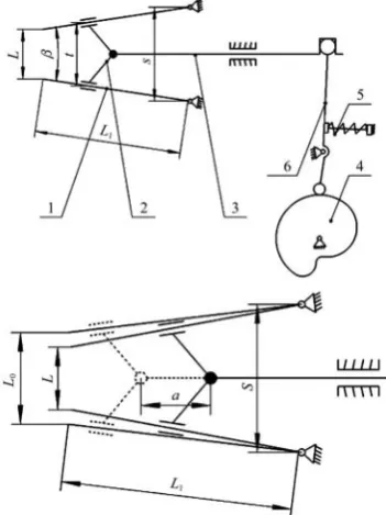
Figure 8 shows kinematic diagram of executive component for picking seedlings. The opening and closing of the needles are realized through push rod sliding the sleeve rings on the two pointers, while the stretching and drawing back of the pushrod is controlled by the cams and springs.
1. Gripper needle 2. Sleeve ring 3. Pushrod 4. Cam 5. Spring 6. Shift fork Figure 8 Kinematic diagram of executive component for picking
seedlings
According to the size of the seedling pot, the opening distance of the two gripper needles when inserted into the seedling pot is set as L0=18 mm, and the distance between the two gripper needles when they are at the upper hinge point of the clamping hand is set as
s=40 mm. When the needles are inserted into the seedling pot at a depth of 30mm and grip the pot, the relation of the angle β between the two needlesand opening distance L of the needles is:
1
sin
2 2
β s L
L −
= (5)
The moisture of tomato seedlings is considered as 55% according to the physical characteristics, the adhesive force FP = 2.67 N, and the compressional displacement of the substrate is 10 mm (L=8 mm). Then the determined values (in which μwas determined as 0.52[33]) are substituted into Equations (4) and (5), and the compressive resistance of the seedling pot was calculated as
F=1.62 N which smaller than the measured maximum compressive resistance of seedling pot which is 4.70 N. At same time, the angle between the two needles is β=17.5° which is smaller than the taper angle of seedling pot which is 19°. These parameters can ensure smooth seedling picking without damage to the seedling pots.
5.2 Parameters of the sleeve rings and pushrod
There is a fixed connection between the sleeve rings and the pushrod. The stretching and drawing back of the pushrod controls the opening and closing of the needles. The design principle of the rings is as follows: the two rings should slide smoothly on the gripper needles, and the distance between the two rings should meet the demand of opening distance and gripping angle of the two gripper needles; the rings should be at a suitable height and meet the position requirement of the gripper needles relative to the pushrod. The distance between the two rings should be t=24 mm in the design, and height should be h=40 mm, as is shown in Figure 8b.
The material of the pushrod is stainless steel, with a diameter Φ 8 mm. The head is fixed with a ring, and the rear end contacts with the shift fork through the shift fork seat. The length of the pushrod should meet the position requirement for the motion of the shift fork and reciprocating motion of the rings. Therefore, the designed length of the pushrod is 135 mm. The initial position of the pushrod should ensure that the rings are away from the seedling trays when the gripper needles insert into the pots. Based on the determined opening distance between the gripper needles, the stretching distance of the pushrod is obtained as a=20 mm by graphical method, as is shown in Figure 8.
5.3 Design and calculation of cams and shift fork
The cam moves synchronously with crank I by key joint. It drives the shift fork by changes of contour line and moves the pushrod to corresponding positions at each stage of seedling picking. Figure 9 shows the movement of the shift fork from the lowest position to the limit position, driven by the cam.
Design requirements of cam and shift fork:
(1) In the seedling picking stage, the clamping hand slowly grips the seedling; in the seedling dropping stage, the clamping claw is able to release the seedling immediately and retreat from the pot.
(2) During the period between seedling dropping and next seedling picking, the two gripper needles should be widely open to prepare for the next seedling picking.
(3) The stretching distance of the pushrod should be 20 mm, namely, the travel distance of the shift fork from position A to position B along the pushrod is 20 mm (Figure 9).
(5) The horizontal and vertical distances between the cam center and shift fork center were 2 mm and 14 mm respectively. The angle between two limit positions (from B to A) of the shift fork is δ=30° (Figure 9).
1. Shift fork 2. Cam
Figure 9 Limit positions of cam and shift fork
The structures of the cam and shift fork are shown in Figure 10. According to the design requirements, the height of the shift fork is
H=50 mm, and the width is B=35 mm. In the movement stage I, the clamping claw inserts into the pot and slowly grips the seedling. In the stage II, it pulls out the pot and moves downwards by keeping the clamping, and swiftly drops the seedling at the end of stage II and the beginning of stage III. The shift fork resets driven by the spring to keep the gripper needles open until the stage I in next turn. The angle at stage I, II and III was 39°, 176°, and 145°, respectively. It is determined that the radius of the cam was 12 mm and effective travel of the cam was 3 mm.
Figure 10 Structure diagram of cam and shift fork
6 Experiments
In order to test the working performance of the designed automatic transplanting device of potted tomato seedlings, an indoor experiment was conducted under room temperature of 25°C and relative humidity of 40% (Figure 11).
Figure 11 Automatic transplanting test of tomato pot seedlings
6.1 Experiment materials
The variety of the tomato seedlings was Jinguan 19. The tomato seedlings were cultivated in 128-grid seedling trays, and the seedling substrate was made up of peat and perlite with a volume
ratio of 2:1. After sowing the seeds, the substrate was covered with vermiculite. Fifteen potted seedlings trays were selected, and the seedling emergence rate was controlled to 85% of each (i.e. 108 seedlings per tray). The moisture content of potted seedlings was about 55%.
6.2 Test indexes
The seedling picking rate and leakage rate are two important indexes to evaluate the working performance of the transplanting device and can be calculated by:
0
= A 100%
W
A × (6)
0
= 1 C 100%
M A
⎛ ⎞
×
⎜ ⎟
⎝ - ⎠ (7) where, W is seedling picking rate; M is leakage rate; A is the number of seedlings picked up; A0 is the total number of seedlings; C is the number of seedlings dropped successfully.
6.3 Test method
Firstly, a tray of seedlings was placed in the vertical seedling supply device. The long pin axle transmitted by two synchronized chains was used to stick the seedling tray. The control system was started to move the device to the left limit position, and it automatically stopped at the rightmost grid of the first row. Finally, the variable frequency motor drove the seedling picking and transplanting mechanism to work continuously at the frequency of 12.5 Hz, 18.8 Hz and 25 Hz, with corresponding transplanting frequencies of 60 seedlings, 90 seedlings and 120 seedlings per minute. After the 15 trays of seedlings were all transplanted, all test data were recorded and were substituted into Equations (6) and (7) for index calculation.
6.4 Results and analysis
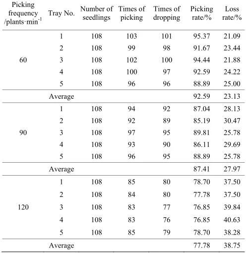
Table 2 shows the test results. The number of seedlings successfully picked up is the number of undamaged seedlings (neither the seedling leaves nor stems were damaged and over 2/3 of substrate was picked up). The number of seedlings successfully dropped refers to the number of seedlings dropped into the planting device with only minor damage (no damage to stems and leaves and the pot was not broken by contact with the planting device).
Table 2 Results of automatic seedlings picking test
Picking frequency
/plants·min-1 Tray No.
Number of seedlings
Times of picking
Times of dropping
Picking rate/%
Loss rate/%
60
1 108 103 101 95.37 21.09
2 108 99 98 91.67 23.44
3 108 102 100 94.44 21.88
4 108 100 97 92.59 24.22
5 108 96 96 88.89 25.00
Average 92.59 23.13
90
1 108 94 92 87.04 28.13
2 108 92 89 85.19 30.47
3 108 97 95 89.81 25.78
4 108 93 90 86.11 29.69
5 108 96 95 88.89 25.78
Average 87.41 27.97
120
1 108 85 80 78.70 37.50
2 108 84 80 77.78 37.50
3 108 83 77 76.85 39.84
4 108 83 76 76.85 40.63
5 108 85 79 78.70 38.28
The test results of picking rate and loss rate of automatic transplanting device under different transplanting frequency are shown in Figure 12.
Figure 12 shows that the highest success rate of seedling extraction is 92.59% and the lowest rate of loss is 23.13% when the transplanting frequency is 60 plants/min; when the transplanting frequency was 120 plants/min, the success rate of seedling extraction was the lowest (77.78%), and the highest rate of loss was 38.75%.
a. Picking
b. Dropping
Figure 12 Results of picking test under different transplanting frequencies
7 Discussion
With the increase of transplanting frequency, the seedling picking rate decreased and leakage rate increased. Especially when transplanting frequency was raised from 90 to 120 seedlings per minute, the drop of seedling picking rate and rise of leakage rate were very prominent. Results showed the main reasons for this are as follows:
(1) The increase of transplanting frequency results in faster seedling picking speed, thus the time for the two gripper needles gripping and picking up the seedlings was reduced. In this way, the clamping stability was reduced and more failures in seedling picking were caused.
(2) With the increase of transplanting frequency, speed of seedling picking mechanism accelerates, the striking momentum between the gripper needles and the pots also increased. In this way, the pots got easily damaged, and more failures occurred.
(3) The increase of transplanting frequency results in faster seedling dropping speed, namely, the seedling feeding speed and acceleration increased after the clamping claw picked up the seedlings (with increase of inertia force). This easily caused that seedlings were thrown out from the claw, or damaged by collapsing with planting device resulting from the high acceleration.
(4) The three reasons listed above jointly resulted in an increase in leakage rate of the automatic transplanting device.
Based on the reasons listed above, there are several methods to further improve the working performances in high-speed condition
of automatic transplanting device of potted tomato seedlings and ensure transplanting quality:
(1) Improving the structure of clamping hands, (2) Increasing the depth of seedling picking,
(3) Reducing inertia force by fixing springs or balance weights on the device where the rotary inertia is high.
In total, the automatic transplanting device can achieve efficient transplanting of tomato seedlings, with good working performances when transplanting frequency is 60 seedlings per minute.
8 Conclusions
In this study, an automatic device for vegetables transplanting was designed, which was composed of horizontal and longitudinal tray moving mechanism, five-bar fixed and axis gear system combined seedling extraction mechanism, rotary planting mechanism and control system. The device is able to transmit the pot seedling automatically, pick up the seedling accurately and transplant vegetables with high efficiency. The parts of mechanism moved orderly and accurately.
The “sickle” type trajectory was proposed. The optimum trajectory parameters and stress force of the seedling collection mechanism are determined with the aim of combining agricultural machinery with transplanting agronomy. According to the force condition for clamping tomato seedling smoothly, the working parameters of the executing parts were calculated. In order to meet the position and posture demands of seedling picking and dropping with minor shocks, the key structure and working parameters of the cam and shift fork were determined as height of shift fork H=50 mm, width B=35 mm, base radius of cam was 12mm and effective travel distance was 3 mm.
The results of the machine test showed, when room temperature was 25°C, seedling age was 40 d, moisture content was 55%, and the transplanting frequency was 60-120 plants/ min, the success rate of seedling extraction was 92.59%-77.78% and the rate of leakage was 23.13%-38.75%; When the transplanting frequency was 90 plants/min, the success rate of seedling extraction was 87.41%, and the rate of leakage was 27.97%. When the transplanting frequency was 60-90 plants/min, the device can meet the design requirements of high speed transplanting of potted vegetable seedlings. However, when the transplanting frequency was more than 90 plants/min, the operation quality was greatly influenced. The operation stability can be improved by reducing the inertial force of high speed rotation.
Acknowledgements
The work was sponsored by the National Natural Science Foundation of China (Grant No.51505130), the National Key Research and Development Program of China Sub-project (No.2017YFD0700800), the Innovation Scientists and Technicians Troop Construction Projects of Henan Province (No.184200510017), and the key scientific and technological projects of Henan Province (No.172102110021).
[References]
[1] Wang C, Sun J, Wang T, Yang G H. Development situations and prospects of vegetable industry in China. Journal of Northern Horticulture, 2014; 4: 162–165. (in Chinese)
[2] He Q Y, Yin W Q, Zhang S X. Performance analysis of three types of transplanters used in dryland. Journal of Anhui Agricultural Sciences, 2006; 34(24): 6722–6723, 6725.
and performance experiment of cantilever cup vegetable transplanter. Transactions of the CSAE, 2011; 27(11): 21–25. (in Chinese)
[4] Zha Y H. Develop of two model rape transplanter and it’s application effects. Journal of Agricultural Mechanization Research, 2003; 3: 28–29. (in Chinese)
[5] Liu L, Chen Y C, Zhang X. The application and development overview of the corps transplanting technology. Journal of Agricultural Mechanization Research, 2008; (9): 240–243.
[6] Wang X D, Feng J. State and development of transplanting mechanization with mulch film at home and abroad. Journal of Chinese Agricultural Mechanization, 2005; 3: 25–28.
[7] Bao C J, Li B. The research progress of rice transplanter in Japan. Transactions of the CSAM, 2004; 35(1): 162–166. (in Chinese)
[8] Ni Y L, Jin C Q, Liu J. Design and experiment of system for picking up and delivering seedlings in automatic transplanter. Transactions of the CSAE, 2015; 31(23): 10–19. (in Chinese)
[9] Chen J N, Huang Q Z, Wang Y, Zhang G F. Kinematics modeling and analysis of transplanting mechanism with planetary elliptic gears for pot seedling transplanter. Transactions of the CSAE, 2012; 28(5): 6–12. (in Chinese)
[10] Zhou M F, Yu G H, Zhao Y, Hu H J, Liao Z P, Zhao X. Parameter optimization and test on pick-up mechanism of planetary gear train with ellipse gears for vegetable plug seedling.Transactions of the CSAE, 2014; 30(18): 13–21. (in Chinese)
[11] Yu G H, Liu B H, Zhao Y, Sun L, Xie Y L. Kinematic principle analysis of transplanting mechanism with planetary elliptic gears in automatic vegetable transplanter. Transactions of the CSAM, 2011; 42(4): 53–57. (in Chinese)
[12] Chen J N, Wang Y, Huang Q Z, Huang H M, Wu C Y, Zhang P. Optimization and test of transplanting mechanism with planetary deformed elliptic gears for potted-seedling transplanter. Transactions of the CSAM, 2013; 44(10): 52–56. (in Chinese)
[13] Ye B L, Yu G H, Chen Z W, Zhao Y. Kinematics modeling and parameters optimization of seedling pick-up mechanism of planetary gear train with ecce-ntric gear and non-circular gear. Transactions of the CSAE, 2011; 27(12): 7–12. (in Chinese)
[14] Yu Y X, Luo C X, Yu G H, Zhao X, Yu T F. Parameters optimization of pick-up mechanism of planetary gear train with ellipse gears and incomplete non-circular gear. Transactions of the CSAM, 2013; 44(6): 62–68. (in Chinese)
[15] Yu G H, Chen Z W, Zhao Y, Sun L, Ye B L. Study on vegetable plug seedling pick-up mechanism of planetary gear. Journal of Mechanical Engineering, 2012; 48(13): 32–39.
[16] Han C J, Yang W Z, Zhang X J, Guo H, Yin W Q. Design and test of automatic feed system for tray seedlings transplanter. Transactions of the CSAE, 2013; 29(08): 51–61. (in Chinese)
[17] Chen F. The study on transporting,metering system of block seedling transpanter. MS Dissertation. Shihezi: Shihezi University, 2005. (in
Chinese)
[18] Chen F, Li Z X, Wang W X, Chen Y C. Dropping monitor system design of transplanter. Journal of Shihezi University: Natural Science, 2004; 22(5): 439–440.
[19] Jin X, Du X W, Geng G S, Ji J T, Dong X, Liu W X. Experiment on planting system of 2ZDJ-2 transplanter. Transactions of the CSAM, 2015; 46(12):26–31. (in Chinese)
[20] Wan L, Wang C, Che G. Improved design and experiments of small-size vegetable transplanter. Transactions of the CSAE, 2011; 27(6): 117–122. (in Chinese)
[21] Zhao Y, Huang J M, Zhang G F, Zhao X. Kinematic analysis and optimization of transplanting mechanism with deformable elliptic gears transmission. Transactions of the CSAM, 2011; 42(4): 48–52. (in Chinese)
[22] Jin X, Du X W, Yang C H, Ji J T, Dong Z, Yan H. Design and experiment on automatic transporting mechanism for vegetable potted seedlings. Transactions of the CSAM, 2016; 47(7): 103–111. (in Chinese)
[23] Yi S J, Liu Y F, Wang C, Tao G X, Liu H Y, Wang R H. Experimental study on the performance of bowl-tray rice precision seeder. Int J Agric & Biol Eng, 2014; 7(1): 17–25.
[24] Feng Q C, Zhao C J, Jiang K, Fan P F, Wang X. Design and test of tray-seedling sorting transplanter. Int J Agric & Biol Eng, 2015; 8(2):14–20.
[25] Prasanna Kumar G. V., Raheman H. Automatic feeding mechanism of a vegetable transplanter. Int J Agric & Biol Eng, 2012; 5(2): 20–27. [26] Ye B L, Yi W M, Yu G H, Gao Y, Zhao X. Optimization design and test
of rice plug seedling transplanting mechanism of planetary gear train with incomplete eccentric circular gear and non-circular gears. Int J Agric & Biol Eng, 2017; 10(6): 43–55.
[27] Chen J N, Wang B H, Ren G Y, Huang Q Z. Kinematics modeling and parameters analysis of seven-linkage vegetable seedling transplanting mechanism. Transactions of the CSAM, 2010; 41(12): 48–53. (in Chinese)
[28] Merlet J. Algebraic geometry tools for the study of kinematics of parallel manipulators. Kluwer Academic Publishers, 1993; 183–194.
[29] Chen L Z. Mechanical optimization design method. Metallurgical Industry Press, 1985; pp.43–45. ISBN 9787502436360 (in Chinese) [30] Zhao Y. Agricultural machinery analysis and synthesis. Machinery
Industry Press, 2009; pp.38–42. ISBN 9787111250005. (in Chinese) [31] Zhao Y, Yu G H, Chen J N. Mechanism dynamics sequence-solution
method and its application. ASME Journal of Computational and Nonlinear Dynamics, 2007; 2(2): 105–113.
[32] Zhang G F, Zhao Y, Chen J N. Dynamics analysis of elliptic gear based on dynamics sequence solution. Journal of Zhejiang Sci-Tech University, 2005; 22(2): 157–161. (in Chinese).