Development of a PVDF sensor for potted seedling clamping force of
vegetable transplanting
Jiangtao Ji
1,2,
Jingwei Sun
2,
Xin Jin
1,2*,
Mingyong Li
1,
Xinwu Du
1(1. College of Agricultural Equipment Engineering, Henan University of Science and Technology, Luoyang 471003, China; 2. Collaborative Innovation Center of Machinery Equipment Advanced Manufacturing of Henan Province, Luoyang 471003, China)
Abstract: Aiming at the problems of loose bowl, nutritive bowl damage and planting leakage caused by lack of perception and detection of seedling clamping force in vegetable transplanting, a semi-micro-column structure sensor for measuring potted seedling clamping force was developed based on polyvinylidene fluoride (PVDF) piezoelectric film. The diameter of the semi-micro-column is 4 mm. The size of the force probe is 14 mm×30 mm, the encapsulation position of the force probe is 25 mm away from the tip of the seedling claw. The hardware circuit for sensor signal acquisition including pre-amplification module, power frequency notch module, low-pass filter module, processor module and power module was designed. The circuit completes charge-voltage conversion, clamping force signal amplification, power frequency signal elimination, vibration and noise elimination, and ensures the accurate acquisition of clamping force signal. In order to verify the sensor performance, sensor calibration tests and indoor experiments were carried out respectively. The calibration tests showed that the sensitivity of the clamping force sensor was 0.5264 V/N, the linearity was 4.74%, the accuracy was 6.51%, the hysteresis was 3.63%, and the range was 8 N under the impact of different waveforms and frequencies, which fully meet the accuracy requirements of the clamping force detection during transplanting. Indoor experiments showed that the clamping force sensor had good stability and adaptability under different seedling frequencies. The sensor can provide useful reference for the perception and detection of seedling clamping force and the feedback regulation of seedling clamping force.
Keywords: seedling clamping force, PVDF piezoelectric film, semi-micro-column structure, hardware circuit
DOI: 10.25165/j.ijabe.20191205.5094
Citation: Ji J T, Sun J W, Jin X, Li M Y, Du X W. Development of a PVDF sensor for potted seedling clamping force of vegetable transplanting. Int J Agric & Biol Eng, 2019; 12(5): 111–118.
1 Introduction
The seedling clamping force refers to the force of seedling picking mechanism on nutritive bowl in the process of picking and throwing seedlings in vegetable transplanting operation. Its size is the key factor to determine the damage rate of nutritive bowl and the success rate of seedling picking. Most of the existing seedling picking mechanisms adopt pure mechanical clamping mode, lacking the perception and detection of the clamping force[1-5]. There are some problems in the seedling picking operation, such as loose bowl, nutritive bowl damage and planting leakage caused by too large or too small clamping force, which affect the survival rate and success rate of transplanting, resulting in the decline of transplanting quality and crop yield[6-9]. Therefore, the research on the perception and detection technology of seedling clamping force can provide evaluation means for the design and optimization of seedling picking mechanism, provide feedback for regulating seedling picking strength of seedling claw, and then improve the quality of
Received date: 2019-04-21 Accepted date: 2019-09-09
Biographies: Jiangtao Ji, PhD, Professor, research interests: vegetable production mechanization, Email: [email protected]; Jingwei Sun, Master candidate, research interests: precision agriculture technology, Email: [email protected]; Mingyong Li, PhD candidate, research interests: agricultural information and intelligent machine, Email: [email protected]; Xinwu Du, PhD, Associate Professor, research interests: farm machine and mechanical reliability, Email: [email protected].
* Corresponding author: Xin Jin, PhD, Associate Professor, research interests: agricultural utility robot technology. Henan University of Science and Technology, Luoyang 471003, China. Tel: +86-379-64877817, Email: [email protected].
seedling transplantation and crop yields.
designed a PVDF tactile sensor, which can effectively detect the surface roughness characteristics of fruits and vegetables via processing of tactile signal. Yu[22] established the mechanical model of two-fingered manipulator grasping, By means of computer-aided software simulation, the gasket structure favorable to sensor placement was obtained. Cui et al.[23] proposed using resistance strain gauge to detect the clamping force of the clamp finger, and using flexible lever amplification mechanism to realize the measurement of micro-clamping force. Zhou et al.[24] made a sliding sensor using varistor to sense the clamping force in the process of grasping fruits and vegetables. In the existing literature, most of them improve the quality of transplantation through mechanism design and optimization. Although the detection of clamping force is involved, it mostly focuses on the field of fruit and vegetable harvesting. The detection of clamping force in the process of vegetable transplanting has not yet been seen.
Aiming at the problems of loose bowl, nutritive bowl damage and planting leakage caused by lack of perception and detection of seedling clamping force in vegetable transplanting, a semi-micro-column structure sensor for potted seedling was designed based on PVDF piezoelectric film, and the calibration tests of the sensor were carried out. Finally, the stability and adaptability of the sensor were verified by the indoor experiments of the clamping force in seedling picking with the designed sensor.
2 Analysis of potted seedlings clamping force
In the process of automatic transplanting, it is the key to accurately and reliably detect the clamping force of seedlings by analyzing the stress and compression process of potted seedlings and reasonably determining the structure and installation mode of sensors.
1. Nutritive bowl 2. Seedling claw 3. Potted seedling
Note: F1 and F2 are the clamping force of the seedling claw on the nutritive bowl, N; f1 and f2 are the static friction force produced by the seedling claw on the contact surface of the nutritive bowl, N; F0 is the resultant force between the weight of the nutritive bowl and the adsorptive force between the nutritive bowl and the seedling tray, N; F2' is the average force of the nutritive bowl on the seedling claw, the size of which is equal to F2, N; Fx is the action force of the
nutritive bowl at different positions on the seedling claw, N; β is the clamping angle.
Figure 1 Analysis of the clamping force of the nutritive bowl during the seedling process
Regardless of creep and inhomogeneity of the nutritive bowl, the force analysis of the nutritive bowl at the clamping stage is shown in Figure 1. Assume that the seedling claw is inserted parallel to the side of the nutritive bowl, then the seedling claw is in
clamping state, and the line AB is parallel to the side line of the nutritive bowl. As can be seen from Figure 1: During the clamping process, the compression of nutritive bowl increases with the increase of the insertion depth of the seedling claw. The clamping force at different contact positions between the seedling claw and the nutritive bowl is also different, and the size of the clamping force increases with the increase of the insertion depth. In order to successfully remove the seedlings, the following conditions should be satisfied:
1 2 0
( )cos 2 sin
2 x 2
f + f β + F β =F (1)
where, Fx represents the force exerted by the nutritive bowl at
different positions on the seedling claw. The direction is perpendicular to the contact surface. The size of the force is as follows:
Fx=σxA (2)
where, σx is the compressive strength of the nutritive bowl at
different positions and increasing with the increase of compressive deformation, kPa; A is the clamping contact area of the nutritive bowl, m2.
In the calculation, we usually simplify the clamping force of the seedling claw on both bowl sides to F1 and F2, and there is a clamping force error caused by the different insertion depth of the seedling claw. In order to compensate for clamping force error, a semi-micro-column structure sensor based on PVDF piezoelectric film was proposed, which can compensate the difference of the bowl compression at the tip of the seedling claw and the detection position, eliminate the error caused by the difference of clamping force between the end and the measuring point, and detect the change of clamping force more accurately and efficiently.
3 Sensor design
3.1 Measuring principle
PVDF piezoelectric film is a new type of polymer piezoelectric material. It has the advantages of large piezoelectric constant, good flexibility and ductility, high sensitivity and strong mechanical toughness. It can be made into various complex shapes to meet the complex and harsh working conditions in the field. The typical performance parameters of PVDF piezoelectric film used in this paper are shown in Table 1.
Table 1 Typical performance parameters of PVDF
Thickness /μm
Piezoelectric stress constant/pC·N-1
Density /g·cm-3
Elastic modulus /109 N·m-2
d31 d32 d33
52 23 3 –33 1.78 3
a. Force diagram of the semi-micro-column structure
b. Orientation of the piezoelectric crystal axis when the PVDF piezoelectric film
under the force Figure 2 Principle of PVDF Piezoelectric Film
Pressure Measurement
As shown in Figure 2a, the semi-micro column structure uses a flexible material as the basement. When the PVDF piezoelectric film is impacted by external force F, the polarization direction of the film can only be the thickness direction (Z axis direction), because its thickness is 52 μm, which is much smaller than the length and width, and the charge of the PVDF piezoelectric film can only be generated in direction Z. Since the basement is made of a flexible material, the surface stress of the piezoelectric film acted perpendicularly is transformed into tangential strain, and the PVDF piezoelectric film is not placed in the electric field. Therefore, the piezoelectric equation of the piezoelectric film is as follows:
3 31 1 31 F
D d S d
hw
= = (3)
where, D3 is the charge density generated by piezoelectric film; d31
is the piezoelectric stress constant; S1 is the positive strain in the
length direction of piezoelectric film; F is the force acting vertically on piezoelectric film; h and w are thickness and width of PVDF Piezoelectric Film.
The charge quantity Q produced by PVDF piezoelectric film is: Q=D3S (4)
where, Q is the charge output from PVDF piezoelectric film; S is the forced area of PVDF piezoelectric film.
Equations (3) and (4) show that the charge output from PVDF piezoelectric film is linearly related to the vertical force, so its piezoelectric effect can be used to measure the vertical force.
3.2 Sensor structure and encapsulation
The sensor is mainly composed of a force probe, a seedling claw and wire. According to the agronomic and planting requirements, the depth of inserting the seedling claw into the bowl during mechanized transplanting is about 28 mm. In this paper, the force probe is installed 25 mm away from the tip of the seedling claw, which can ensure that the sensitive element contacts the bowl completely when the seedling claw is inserted into the nutritive bowl. The size of the force probe is 14 mm×30 mm, the force probe is embedded in the seedling claw; the inner part of the seedling claw is hollow structure, which facilitates the connection between wire and the signal conditioning circuit. The structure is shown in Figure 3.
1. Force probe 2. Seedling claw 3. Wire Figure 3 Sensor structure diagram
In order to measure the clamping force of seedlings, the PVDF piezoelectric film for measuring pressure is encapsulated in the force
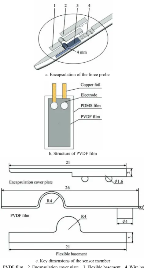
probe. The manufacture and encapsulation of the force probe are shown in Figure 4a, including the PVDF piezoelectric film, the encapsulation cover plate, the flexible basement and the wire hole. Among them, the size of PVDF piezoelectric film is 14 mm×30 mm, because the surface electrodes of PVDF piezoelectric film are very thin, the copper foil and PVDF piezoelectric film are bonded with conductive silver glue to lead the upper and lower electrodes. PDMS (polydimethylsiloxane) film is chosen as the protective layer, and epoxy resin glue is used to bond. The structure of the encapsulated PVDF piezoelectric film is shown in Figure 4b. The flexible basement is a semi-micro-column structure. In order to compensate for the difference of compression between the tip of the clamp and the detection position, and to ensure the integrity of the bowl, the diameter of the semi-micro-column structure is 4 mm, and the flexible basement material is made of silica gel with Shaw hardness of 60 HA. The size structure of the three key components of the PVDF film, encapsulation cover plate, and flexible basement is shown in Figure 4c.
a. Encapsulation of the force probe
b. Structure of PVDF film
c. Key dimensions of the sensor member
1. PVDF film 2. Encapsulation cover plate 3. Flexible basement 4. Wire hole Figure 4 Schematic diagram of the manufacture and
encapsulation of the force probe
flexible substrate is bonded to the picking claw by 502 glue to ensure its firmness. The PVDF piezoelectric film is bent into a circular arc with a diameter of 4 mm and is bonded to the flexible substrate by epoxy resin adhesive. The packaging cover plate is installed on the top layer to ensure the packaging strength by connecting the packaging groove and thread with the seedling claw. Finally, the silicone rubber is used to seal all parts to improve its waterproof and dust-proof performance of the sensor.
3.3 Design of sensor hardware circuit
Due to the small surface charge generated by the external force of the PVDF piezoelectric film. The vibration interference of
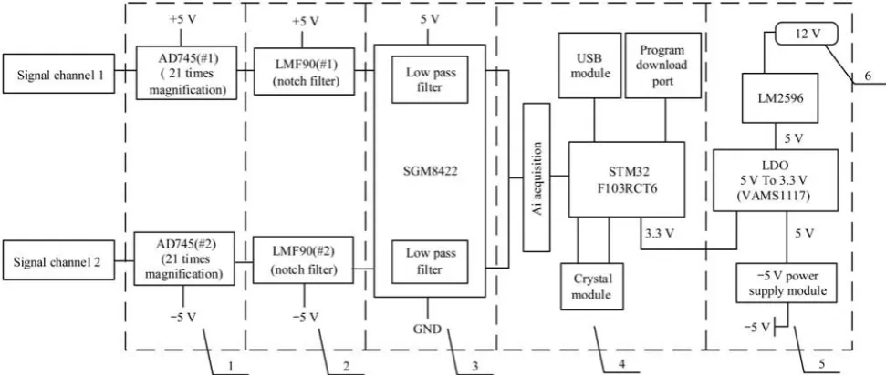
seedling operation environment is large, which results in small signal amplitude and high noise of sensor output signal. In order to improve the signal-to-noise ratio, a signal conditioning circuit is designed to amplify and regulate the charge signal generated by the sensor. The conditioning circuit includes pre-amplification module, power frequency notch module and low-pass filter module. At the same time, in order to avoid the problem of poor stability and noise caused by the traditional op-amps, resistors and capacitors, the conditioning circuit mainly designed with functional integrated chips, including AD745, LMF90 and SGM8422, as shown in Figure 5.
1. Pre-amplification module 2. Power frequency notch module 3. Low-pass filter module 4. Processor module 5. Power module 6. Input voltage Figure 5 Signal acquisition and processing hardware circuit structure
Among them, the pre-amplification module is designed based on instrumentation amplifier AD745. Its main function is to convert the high impedance input into low impedance output, convert the output charge of PVDF piezoelectric film into voltage, and perform 21 times amplification on the sensor output signal. In order to reduce the influence of high frequency noise during transplanting operation, a two-stage power frequency and double frequency notch circuit is designed based on LMF90 for signal filtering, and the notch frequency is 50 Hz. Considering that the two clamping force sensor signal processing needs to construct the filter, the single-chip dual operational amplifier SGM8422 is used to design the low-pass filtering module. As shown in Figure 6, the processing module adopts STM32F103RCT6 MCU produced by Yifa Semiconductor Company, which integrates A/D conversion function and can convert voltage analog signal into digital signal, and the processing module is also equipped with USB communication module, program download port and crystal module. It is convenient for data transmission and program burning to ensure the normal operation of the microcontroller. The input voltage of the hardware circuit is 12 V. In order to ensure the normal operation of each module, LM2596 series integrated chip is used to regulate the supply voltage. First, the 12 V input voltage is stepped down to 5 V, and then the 5 V voltage is converted to 3.3 V by ASM1117-3.3 forward regulator to power the microcontroller. Since the AD745 and LMF90 chips require –5 V power supply, a –5 V power supply module is added to ensure normal operation of the chip.
4 Sensor calibration test
4.1 Establishment of calibration system
The sensor calibration system consists of function signal generator, power amplifier, modal exciter, dynamic force sensor, signal acquisition and analysis device, clamping force detection sensor, signal processing hardware circuit and data display software. The block diagram of the calibration system is shown in Figure 6.
Firstly, the function signal generator gives a specified waveform input signal, which is amplified by a power amplifier to enable it to have load capacity and drive the modal exciter to generate corresponding amplitude vibration. Then, the vibration of the modal exciter is loaded on the clamping force detection sensor, and the dynamic force sensor installed on the modal exciter is used to measure the output force of the exciter, and the data is connected to the signal acquisition, analysis device and displayed synchronously on the data display software; At the same time, the charge generated by the clamping force sensor is outputted as a voltage by the signal processing hardware circuit, and which is connected to the data display software on the computer. The pressure signal and voltage signal detected are displayed and recorded synchronously by the data display software.
Shibo Science and Technology. The maximum excitation force is 20 N and the maximum excitation stroke is 6 mm. The dynamic force sensor adopts 502F01 sensor of Yangzhou Michael Measurement and Control Company with a sensitivity of 22.44 mv/N and a maximum range of 200 N. The signal acquisition and analysis device adopt DH5902N solid data acquisition and analysis system of Jiangsu Donghua Testing Company, which can realize multi-channel data acquisition at the same time. Data display software is a computer software for signal acquisition and analysis device, which can realize real-time processing, storage and display of data, and fully meet the requirements of calibration test.
Figure 6 The block diagram of sensor calibration system
4.2 Calibration method
The calibration of the sensor is to establish the relationship between the sensor output and the input, and to calculate the performance parameters of the sensor. According to the test of mechanical characteristics of vegetable potted seedlings based on
existing relevant literature[25-28], we selected sensor calibration in the range of 0-8 N, and the calibration site is shown in Figure 7. In order to simulate the force on the bowl and the frequency of seedling picking in transplanting, the function signal generator was set to generate 0.75 Hz, 1 Hz, 1.25 Hz sine and square wave to start-up vibration exciter respectively. By first increasing and then reducing the gain of power amplifier, the sensor's stress was increased to 8 N and then reduced to 0 N. The data display software was used to store the pressure and voltage data. Each waveform and frequency collected 40 groups of data, 20 groups in the ascending process and 20 groups in the descending process. A total of 240 groups of data were collected. We record the detected pressure and voltage signals by calibrating the system's data display software. Finally, the experimental data is fitted using the least squares method to calculate the sensor parameters.
Figure 7 Sensor calibration testing field
4.3 Calibration results and analysis
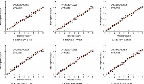
The transplanting device has severe vibration and impact during the working process, and has high requirements on the stability of the sensor. In order to investigate the stability and adaptability of the sensor, the range, sensitivity, linearity, accuracy, and hysteresis were selected for calibration in combination with the high-speed operation of the seedling claw. The calibration curves of clamping force sensor are shown in Figure 8.
a. Sine wave 0.75 Hz b. Sine wave 1.00 Hz c. Sine wave 1.25 Hz
(1) Range of sensor
According to the sensor calibration data and the related mechanical characteristics of the potted seedlings, the output voltage measurement range of the sensor is 0-5 V, and the range is 5 V. The measuring range of clamping force is 0-8 N and the range is 8 N.
(2) Sensitivity of sensor
Sensitivity of sensor is the ratio of the change in output (Δy) to the change in input (Δx). It is the slope of output characteristic curve, usually denoted by S.
lim y
n
x
d y S
x d
→∞ Δ
= =
Δ
(5)
According to Equation (5), the sensitivities of the designed sensor under sine and square wave shocks with frequencies of 0.75 Hz, 1 Hz and 1.25 Hz are 0.4996 V/N, 0.5105 V/N, 0.5287 V/N, 0.5492 V/N, 0.5309 V/N and 0.5396 V/N respectively, with an average sensitivity of 0.5264 V/N.
(3) Linearity of sensor
The linearity of the sensor is an important index to describe its waiting characteristic, also known as non-linear error. It represents the degree of deviation of the actual relationship curve between input and output from the fitting line, usually denoted by δ.
max 100%
FS
Y Y
Δ
= ×
δ
(6)
where, ΔYmax is the maximum deviation between the actual output
value of the sensor and the fitting line, YFS is the measurement range
of the sensor.
After analyzing and calculating the data, under the impact of sine wave and square wave with the frequency of 0.75 Hz, 1 Hz, 1.25 Hz, the maximum deviation between the designed sensor output value and the fitted line is 0.2368 V, the output voltage range is 5 V, and the linearity of the sensor calculated by Equation (6) is 4.74%.
(4) Accuracy of sensor
The accuracy of the sensor (γ) indicates the reliability of the measurement results. It is usually expressed as the ratio of the measured maximum absolute error (ΔA) to its output full range (YFS).
The calculation formula is as follows:
100%
FS
A Y
Δ = ×
γ (7)
In the process of sensor calibration, the maximum absolute errors of six groups test are 0.1256 V, 0.2356 V, 0.1963 V, 0.3256 V, 0.2456 V and 0.2156 V, respectively. The accuracy of the six groups test obtained by Equation (7) is 2.51%, 4.71%, 3.93%, 6.51%, 4.91%, 4.31%, the accuracy of the sensor is 6.51%.
(5) Hysteresis of sensor
The hysteresis of sensor refers to the phenomenon that the output characteristic curves do not coincide during the change of the input amount from small to large and from large to small. The hysteresis error (γH) is usually expressed by the ratio of half of the
maximum output difference (ΔHmax) to its full range output value
(YFS) between forward and reverse stroke. The calculation formula
is as follows:
max
= 100%
2
H
FS
H Y
Δ
± ×
γ (8)
According to the calibration fitting data: Under the impact of different frequencies and waveforms, the maximum output error of the sensor is 0.3632 V, so the hysteresis error of the sensor is 3.63%.
The fitting results show that: Under the impact of different waveforms and frequencies, the linear determinant coefficients of the designed sensor are 0.9879, 0.9855, 0.9913, 0.9861, 0.9899 and 0.9868, respectively. The average linear determinant coefficient is 0.9879. It shows that the force acting on the sensor is highly linear with the output voltage, and the sensitivity of the sensor obtained in each test is very small. It shows that the clamping force sensor designed in the measurement range has good repeatability and stability.
5 Experiments
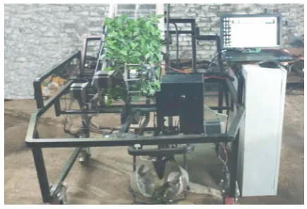
In order to verify the stability and adaptability of the designed clamping force sensor, the seedling clamping force experiment was carried out on the fully automatic vegetable transplanting test bench. The experiment site is shown in Figure 9.
Figure 9 The clamping force detection indoor experiment site
5.1 Experiment materials
The Experiment seedling was Jianjiao No.1, with a seedling age of 40 days and a seedling height of 10-12 cm. The plug is a 128-hole square vertebral body hole plate. The upper hole diameter is 32 mm×32mm, the lower diameter is 13 mm×13 mm, the depth of the hole is 42 mm, and the cell volume is 20 mL. The substrate is made of perlite, vermiculite and peat at a volume ratio of 6:3:1, with a water content of 50%.
The Experiment equipment includes vegetable transplanting test-bed, clamping force sensor, signal conditioning hardware circuit, the existing clamping force signal monitoring system of our research group and portable computer.
5.2 Experiment method
According to China's dryland transplanting machinery operating standards (JB/T 10291-2013), and combining with the actual production situation[29,30]. Through the PLC control system of vegetable transplanting test-bed, 45 plants/min, 60 plants/min and 75 plants/min were selected respectively, and the frequency of seedlings in each group was 64 holes seedling operation, repeated 5 times, and a total of 15 groups test were carried out. The clamping force of each seedling was recorded, the mean, standard deviation and range of the clamping force of each seedling at different frequencies were counted to analyze the stability of the clamping force sensor; In addition, the integrity rate of the bowl in each group was calculated, and the adaptability of the clamping force sensor under transplanting conditions was studied.
5.3 Results and discussion
between 3.25-3.70 N, the standard deviation is between 0.072-0.096 N, the range is between 0.35-0.57 N, and the bowl integrity is between 78.13%-98.44%.
Table 2 Statistical results of seedling clamping force test
Frequency
/plants·min-1 Number Mean/N
Standard deviation/N
Range /N
Bowl integrity/%
45
1 3.60 0.096 0.42 92.19
2 3.35 0.086 0.51 98.44
3 3.28 0.091 0.43 96.88
4 3.64 0.079 0.56 90.63
5 3.30 0.084 0.48 96.88
Average 3.43 0.087 0.48 95.00
60
1 3.34 0.079 0.35 96.88
2 3.56 0.085 0.53 92.19
3 3.41 0.082 0.52 89.06
4 3.70 0.072 0.49 95.31
5 3.58 0.083 0.46 87.50
Average 3.52 0.080 0.47 92.19
75
1 3.55 0.075 0.41 82.81
2 3.59 0.079 0.53 87.50
3 3.62 0.085 0.34 85.94
4 3.48 0.089 0.57 87.50
5 3.70 0.081 0.41 78.13
Average 3.59 0.082 0.45 84.38
The test results of average value of clamping force and bowl integrity under different transplanting frequencies are shown in Figure 10. The average value of clamping force were 3.43 N, 3.52 N and 3.59 N, the average value of standard deviation were 0.087 N, 0.080N, 0.082N, the average value of range were 0.48 N, 0.47 N, 0.45 N, and the average value of bowl integrity were 95%, 92.19%, 84.38% when the frequency of picking up seedlings were 45, 60 and 75 plants/min, respectively. The results showed that the measured fluctuation range was small and the stability was good when the designed clamping force sensor was used to detect the clamping force. Indoor experiments results show that the clamping force sensor has good stability and adaptability under different seedling frequencies. At the same time, we found the following problems:
(1) When reading the clamping force values, there were many fluctuations and even a few abnormal values near the clamping force values. The main reason for this situation was the bowl substrate was unevenly distributed and the seedling claw were suddenly blocked during the process of inserting the nutritive bowl. In the subsequent optimization process, the filter range of the sensor hardware circuit can be adjusted according to the specific seedling frequency to reduce the interference.
(2) With the increase of seedling picking frequency, although the integrity rate of nutritive bowl has declined, but it was still within the controllable range. The main reason for the decline of integrity rate of nutritive bowl were the vibration of frame and the disturbance of seedling claw when seedling picking at high speed. At present, the current seedling picking mechanism has not reached 75 plants/min. By reducing the speed of seedling picking, adjusting the diameter of semi-micro column structure, reducing the vibration of frame and disturbance of seedling claw, the breakage rate of nutritive bowl can be greatly reduced.
a. Average value of clamping force b. Average value of standard deviation
c. Average value of range d. Average value of bowl integrity Figure 10 Results of seedling clamping force test under
different transplanting frequencies
6 Conclusions
(1) Using PVDF piezoelectric film as sensing element, a semi-micro column seedling clamping force detecting sensor was designed. The size of the force probe is 14 mm×30 mm, the encapsulation position of the force probe was 25 mm away from the tip of the seedling claw. The diameter of the curved silicone basement was 4 mm. It can effectively compensate the difference of the bowl compression between the tip of the seedling claw and the detection position of the bowl, and detect the change of the clamping force more accurately.
(2) The hardware circuit of signal acquisition was designed, including pre-amplification module, power frequency notch module and low-pass filter module, processor module and power module. The seedling clamping force signal was processed, which effectively reduced the noise generated by complex working environment and mechanism vibration in the field.
(3) The calibration test of the sensor shows that the sensitivity of the sensor was 0.5264 V/N, the linearity was 4.74%, the precision was 6.51%, the hysteresis was 3.63%, the average linear determinant coefficient was 0.9879 and the range was 8 N under the impact of different waveforms and frequencies, which fully meet the accuracy requirements of clamping force detection during transplanting. Indoor experiments showed that at the seedling frequency of 45 plants/min, 60 plants/min, 75 plants/min, the clamping force detection value was between 3.25-3.70 N, the average value of the standard deviation was between 0.080-0.087 N, the average value of the range was between 0.45-0.48 N, the average bowel integrity rate was between 84.38%-95%. The measurement range of the clamping force is small, the integrity of the bowel is high, and the sensor has good stability and adaptability.
Acknowledgements
the National Natural Science Foundation of China (No.51875175), the Key Research and Development Program of Guangdong Province (No.2019B020222004), and the Innovation Scientists and Technicians Talent Projects of Henan Provincial Department of Education (No.19HASTIT021), the Innovation Scientists and Technicians Troop Construction Projects of Henan Province (No.184200510017).
[References]
[1] Yu G H, Liao P Z, Xu L H, Zhao P, Wu C Y. Optimization design and test of large spacing planetary gear train for vegetable pot-seedling planting mechanism. Transactions of the CSAM, 2015; 46(7): 38–44. (in Chinese) [2] Zhang Z G, Lv Q G, Chen Q Y, Xu H J, Li H K, Zhang N N, et al. Status analysis of picking seedling transplanting mechanism automatic mechanism for potted flower. Journal of Jiangsu University (Natural Science Edition), 2016; 37(4): 409–417. (in Chinese)
[3] Gao F, Li H C. Research on the influence of vegetable mechanization production on the planting quality of seedlings. Journal of Agricultural Mechanization Research, 2018; 40(12): 125–129. (in Chinese)
[4] Konishi T, Horio M, Yoshida S. Development of high performance rice transplanter. Journal of the Japanese Society of Agricultural Machinery, 2010; 51(5): 89–95.
[5] Liu J D, Cao W B, Tian D Y, Tang H Y, Zhao H Z. Kinematic analysis and experiment of planetary five-bar planting mechanism for zero-speed transplanting on mulch film. Int J Agric & Biol Eng, 2016; 9(4): 84–91. [6] Wang Y W, He Z L, Wang J, Wu C Y, Yu G H, Tang Y H. Experiment
on transplanting performance of automatic vegetable pot seedling transplanter for dry land. Transactions of the CSAE, 2018; 34(03): 19–25. (in Chinese)
[7] Zhou M F, Xu J J, Tong J H, Yu G H, Zhao X, Xie J. Design and experiment of integrated automatic transplanting mechanism for taking and planting of flower plug seedlings. Transactions of the CSAE, 2018; 34(20): 44–51. (in Chinese)
[8] Tong J H, Jiang H Y, Jiang Z H, Cui D. Experiment on parameter optimization of gripper needles clamping seedling plug for automatic transplanter. Transactions of the CSAE, 2014; 30(16): 8–16. (in Chinese) [9] Guo L S, Zhang W J. Kinematic analysis of a rice transplanting
mechanism with eccentric planetary gear trains. Mechanism and Machine Theory, 2001; 36(11): 1175–1188.
[10] Yang Y, Ting K C, Giacomelli G A. Factors affecting performance of sliding-needles gripper during robotic transplanting of seedlings. Applied Engineering in Agriculture, 1991; 7(4): 493–498.
[11] Ting K C, Giacomelli G A, Shen S J. Robot workcell for transplanting of seedlings. Part II: Layout and materials flow. Transactions of the ASAE, 1990; 33(3): 1005–1010.
[12] Ting K C, Giacomelli G A, Shen S J. Robot workcell for transplanting of seedlings. Part II: End-effector development. Transactions of the ASAE, 1990; 33(3): 1013–1017.
[13] COTTON D P J, CHAPPELL P H, CRANNY A. A novel thick-film piezoelectric slip sensor for a prosthetic hand. IEEE Sensors Journal, 2007; 7(5): 752–761.
[14] Liao Q X, Zhang Z, Hu Q L, Xu B. Design and trajectory analysis of
pneumatic picking-up mechanism for rape paper pot Seedling. Transactions of the CSAM, 2017; 48(11): 70–78. (in Chinese)
[15] Zhang L H, Qiu L C, Tian S B, Xiang Q L. Design of a needle clamping claw for plug seedling transplanting. Journal of Shenyang Agricultural University, 2010; 41(2): 235–237. (in Chinese)
[16] Zhao Y, Fan F L, Song Z C, Na M J, Zuo Y J, Feng Y, et al. Design and simulation of inverted vegetable pot seedling transplanting mechanism with conjugate cam. Transactions of the CSAE, 2014; 30(14): 8–16. (in Chinese)
[17] Ji J T, Yang L H, Jin X, Gao S, Pang J, Wang J L. Design and parameter optimization of planetary gear- train slip type pot seedling planting mechanism. Transactions of the CSAE, 2018; 34(18): 83–92. (in Chinese)
[18] Jin X, Ji J T, Liu W X, He Y K, Du X W. Structural optimization of duckbilled transplanter based on dynamic model of pot seedling movement. Transactions of the CSAE, 2018; 34(9): 58–67. (in Chinese)
[19] Jin, X, Li D Y, Ma H, Ji J T, Zhao K X, Pang, J. Development of single row automatic transplanting device for potted vegetable seedlings. Int J Agric & Biol Eng, 2018; 11(3): 67–75.
[20] Ye B L, Yi W M, Yu G H, Gao Y, Zhao X. Optimization design and test of rice plug seedling transplanting mechanism of planetary gear train with incomplete eccentric circular gear and non-circular gears. Int J Agric & Biol Eng, 2017; 10(6): 43–55.
[21] Tao Y T, Zhou J, Meng Y M, Zhang N, Yang X Y. Design and experiment of tactile sensors for testing surface roughness of fruits and vegetable. Transactions of the CSAM, 2015; 46(11): 16–21. (in Chinese) [22] Yun B. Research of grasp technique based on visual and tactile sensing.
Harbin Institute of Technology, 2011. (in Chinese)
[23] Cui Y G, Zhu Y X, Lou J Q, Feng F Y. Detection of finger displacement and gripping force of piezoelectric micro-gripper. Optics and Precision Engineering, 2015; 23(05): 1372–1379. (in Chinese)
[24] Zhou J, Zhu S Q. Slippage Detection in gripping fruits and vegetables for agricultural robot. Transactions of the CSAM, 2013; 44(2): 171–176. (in Chinese)
[25] Hu J, Han L H, Wen Y F, Yu S, Chu J H, Yang Y. Mechanical properties of different vegetable plug seedlings as related to automatic transplanting. Journal of Agricultural Mechanization Research, 2018; 40(5): 132–136. (in Chinese)
[26] Wang Y, Cheng J N, Wu J W, Zhao Y. Mechanics property experiment of broccoli seedling oriented to mechanized planting. Transactions of the CSAE, 2014; 30(24): 1–10. (in Chinese)
[27] Ji J T, Li M Y, Jin X, Pang J, Lv H Z. Experiment on mechanical properties of pepper seedlings based on high-speed and low-loss planting. International Agricultural Engineering Journal, 2017; 26(4): 175–183. [28] Han L H, Mao H P, Liao X H, Hu J P, Yang X J. Design of automatic
picking up seedling end-effector based on mechanical properties of plug seedlings. Transactions of the CSAM, 2013; 44(11): 260–265. (in Chinese)
[29] Li H, Cao W B, Li S F, Liu J D, Chen B B, Mao X X. Development of 2ZXM-2 automatic plastic film mulching plug seedling transplanter for vegetable. Transactions of the CSAE, 2017; 33(15): 23–33.(in Chinese) [30] Zhao Y, Zhang W X, Xin L, Xie J T, Xue X L, Shan Y Y. Design and