Design and implementation of a MIMO MAC protocol for ad hoc
networking
Jason Redi
a, Bill Watson
a, Ram Ramanathan
a, Prithwish Basu
a,
Fabrice Tchakountio
a, Michael Girone
band Martha Steenstrup
ca
BBN Technologies, Cambridge, MA, {jredi, wwatson, ramanath, pbasu, ftchakou}@bbn.com
b
Lucent Technologies, Whippany, NJ, [email protected]
c
Stow Research LLC, Flanders, NJ, [email protected]
ABSTRACT
Multiple Input Multiple Output (MIMO) provides the potential for significant gains in channel capacity and spectral efficiency through its use of multiple element antenna systems and space-time coding. There are numerous published accounts of experimental MIMO communications links with high numbers of transmit and receive antennas, as well as commercial products exploiting MIMO with smaller antenna configurations. However, the use of MIMO as a modulation scheme for mobile ad hoc networking has so far only been explored as part of a theoretic or simulation exercise. In this paper we describe the design and implementation of a MAC protocol for a MIMO system which is designed to exploit the capability of 8x10 MIMO for ad hoc networks. This work is unique in that from the start our design considered the specific capabilities and parameters of an existing 8x10 MIMO physical layer, including nonnegligible decoding delays, variable array size and coding schemes, as well as fixed frame sizes. Furthermore, given the bandwidths and antenna array sizes available, the physical layer design could achieve hundreds of megabits in link capacity, and our MAC protocol therefore needed to be designed and implemented in such a way as to maximize this capacity, particularly in a network multi-hop environment. Our MIMO-MAC protocol provides this capability while supporting multi-hop ad hoc networks through novel schemes for channel access, segmentation/reassembly, ARQ and link adaptation. This paper discusses the challenges and tradeoffs involved in developing a MAC for real MIMO hardware, and briefly describes a subset of our solutions to them.
Keywords: MIMO, network, MAC
1
INTRODUCTION
A mobile ad hoc network (MANET) is a multi-hop wireless network of nodes without the use of infrastructure elements
(such as base stations). Mobile ad hoc networks have seen tremendous growth in their popularity over the past decade. Yet, their performance profile continues to lag behind that of wireline networks, and prevents them from being a first class citizen in the information infrastructure. This motivates the exploitation of recent advances in physical layer technologies such as antenna arrays, new modulation schemes and space-time coding for use in ad hoc networks.
One such promising technology is Multiple Input Multiple Output (MIMO). MIMO has shown to produce significant gains in channel capacity and spectral efficiency through the use of multiple element antenna systems and space-time coding. Typically, a MIMO transmitter consists of a number of antenna elements. An independent stream of data is transmitted using each element. A MIMO receiver consists of the same or larger number of elements, each of which receives all of the streams. However, each stream typically has a different spatial signature due to differences in multipath. The receiver uses sophisticated space-time processing to separate these streams. Thus, MIMO actually exploits multipath instead of being limited by it. Expectedly, it works best in a rich multipath and scattering environment. More details on MIMO can be found in [Fosch98,Gesb03].
In this paper, we describe the design and implementation of a Medium Access Control (MAC) protocol for a 8x10 MIMO-based MANET, in particular based on the Lucent V-BLAST technology [woln98]. The use of MIMO in general and V-BLAST in particular places a number of constraints that render traditional (e.g. 802.11) solutions inadequate. These include nonnegligible encoding and decoding delays, variety of coding schemes depending upon the MIMO “mode,” the need for feedback and training to help process and fixed very long frame sizes.
efficiency of a mere 20% [TradStudy] if traditional RTS-CTS-DATA-ACK is used – more time is spent waiting at the node than transferring useful control/data information. More generally, any handshake oriented mechanism is less efficient in this setting.
Given that TDMA is easy in MANETs only on paper, a variant based on CSMA/CA is more attractive. The obvious remedy is to eliminate handshakes. But sending just a burst of data after carrier sensing has its own problems: How do we handle hidden terminals? If there is no feedback, how do we adjust the backoff/contention window? What can be done to provide reliability? Our solution to these problems are described in this paper.
Our contributions are as follows. We present the first MAC protocol that explicitly and in detail considers the practical constraints of an existing MIMO physical layer. Our MIMO-MAC uses carrier-sense threshold adjustment in lieu of RTS-CTS and an ARQ scheme based on parallel stop-and-wait instead of an obligatory per frame ACK. A novel
contention level indication at the receiver is used to determine the length of the backoff window. Efficient aggregation,
segmentation and reassembly is performed to pack packets efficiently into MAC frames. Link adaptation, namely the selection of the MIMO mode in response to observed channel characteristics ensures optimal MIMO data rates. A number of other practical problems that come up in a system design are tackled to produce a MIMO-MAC based MANET testbed.
The remainder of this paper is organized as follows. In the next section we describe related work. We follow this by an overview of our MIMO-MAC. We then describe individual modules that make up the MAC is separate subsections. This is followed by simulation discussion and conclusions.
2
RELATED WORK
While there has been a considerable amount of work at the PHY layer, MAC solutions suitable for MIMO have been given less consideration. In fact, most previous works on MIMO MACs are almost entirely theoretical. To name a few [BoWi04] provides a theoretical analysis and optimization on the capacity, scheduling and stability regions of MIMO MAC bit-queues. Reference [JoBo03] describes a study of a MIMO MAC in the assumption that the receiver is doing MMSE detection, while [SoUl05] characterizes the optimal transmission directions when incomplete channel state information is available at transmitters. Routing issues in MIMO based MANETs are discussed in [SuSi05].
Perhaps the most important step toward a practical MIMO MAC design is [SuSiA03] and [SuSiJ03]. In particular, this work proposes SMART-MAC (also referred to as CSMA/CA(k)), an extended CSMA/CA that enables user traffic to be sent k times faster than a conventional CSMA/CA over a MIMO channel. However, they do not take into account practical issues such as turn around latency that may affect the performance when implemented.
3
OVERVIEW
MIMO-MAC is specifically designed to work with Lucent Packet BLAST Transceivers mounted on mobile platforms operating in outdoor environments and collectively functioning as an ad-hoc network to transport traffic demanding low delay and a high rate of successful delivery. Like the Packet BLAST Transceiver, MIMO-MAC is agile, adapting to current conditions, and simultaneously exploits and enhances the performance provided by BLAST, while working within the constraints of the specific BLAST implementation. One of these constraints, nonnegligible delays for error-control and BLAST decoding, poses some special challenges for efficient use of the channel and for timely feedback concerning channel conditions and received packets.
MIMO-MAC instances communicate in protocol-data units (PDUs) called MAC Frames or simply frames. MAC Frames are composed of a set of zero or more Turbo-Product Code (TPC) Blocks, called the PHY Payload, and a MAC
Message. MAC Frames are of a fixed duration for each of the configurations. Note that a MAC Frame can contain zero
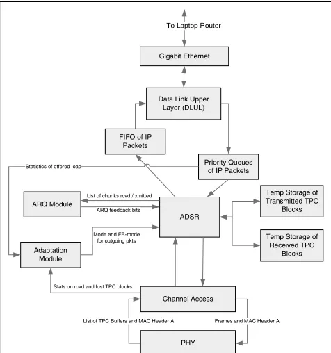
The following paragraphs contain a brief description of each of MIMO-MAC’s modules, which are then described in greater detail in the following subsections:
The framing module (ADSR) acquires packets for forwarding in priority order according to their types of service and segments and concatenates these into frames (the basic data units on which the Packet BLAST Transceiver operates) for transmission to one or more neighboring nodes. It also extracts segments from received frames and reassembles them into packets for further processing by other network control functions. The channel access module (CA) promotes efficient use of the channel, through a variety of complementary techniques for collision avoidance. These include enhanced-range carrier sensing, neighbor-specific backoff based on contention levels provided by the neighbors, and floor acquisition through a request-to-send and clear-to-send transaction. The channel access function also allows reservation of certain time periods specifically for multicast traffic.
The retransmission module (ARQ) detects when packet segments appear to require retransmission and initiates the retransmission of these segments. Retransmission may be triggered by a perceived loss of a transmitted segment or may be performed gratuitously prior to any actual loss or not at all even in the presence of loss, depending upon the packet’s type of service.
The link adaptation (LA) module (Adaptation) uses information provided by the Packet BLAST Transceiver, as well as perceived demand for the link and other higher-level information about the use and performance of the link, to adapt the setting of transmission parameters and to provide to the routing algorithm a set of values for link metrics. In addition, the link adaptation function also provides power control.
The following paragraphs contain a brief description of the flow of data packets through MIMO-MAC.
IP packets to be forwarded through the network arrive from the gigabit Ethernet. DLUL (data link upper layer) does some preliminary processing of these, which includes determining priority and next-hop MAC address, and queues the packets in priority order for framing by ADSR. ADSR receives from Link Adaptation the transmission parameters appropriate for the current channel conditions, which in turn determines the number of data bits that currently can be included in a frame and hence guides the framing process. In addition to framing packets for transmission, ADSR also interacts with ARQ to establish the state information necessary to keep track of which (parts of) packets may require retransmission and to schedule retransmissions when necessary. Once ADSR has filled a frame, it passes the frame to CA, which is responsible for gaining access to the channel prior to frame transmission. After acquiring the channel, CA sends the frame, the prescribed transmission parameters, and any MAC-specific information to the physical layer (PHY). Guided by the specified transmission parameters, the PHY performs error-control and BLAST encoding as well as modulation and then sends the frame and associated information to the appropriate antennas for transmission.
Frames and associated information arrive from the antennas and are processed by the PHY, which handles demodulation and BLAST and error-control decoding. The PHY passes all of this information to CA. CA extracts MAC-specific information, frames which it passes to ADSR, and channel conditions (suggested transmission parameters from the sender and information from the PHY concerning failed receptions) which it passes to Link Adaptation. Link Adaptation uses the channel information as well as information about traffic demand to set transmission parameters and to compute link metrics for routing. ADSR extracts and reassembles packets from frames and interacts with ARQ to determine loss and to return indications back to the sender concerning what (parts of) packets require retransmission. ADSR passes IP packets to DLUL for transmission over the gigabit Ethernet.
ADSR
Temp Storage of Received TPC
Blocks Temp Storage of Transmitted TPC
Blocks Priority Queues
of IP Packets Data Link Upper
Layer (DLUL) Gigabit Ethernet Adaptation Module ARQ Module Channel Access PHY FIFO of IP
Packets
List of TPC Buffers and MAC Header A Frames and MAC Header A List of chunks rcvd / xmitted
ARQ feedback bits Statistics of offered load
Stats on rcvd and lost TPC blocks Mode and FB-mode
for outgoing pkts
To Laptop Router
3.1 ADSR
The Aggregation, Disassembly, Segmentation and Reassembly (ADSR) module is responsible for decomposing network packets into segments and then forming MAC Frames by concatenating segments at the transmitter. ADSR at the receiver side extracts segments from the MAC frames and reassembles network packets. Segment sizes vary with the PHY mode and configuration.
When an ADSR Transmit Event occurs, ADSR attempts to build a burst of MAC Frames, called a stream, to a particular next-hop of up to ADSR-MAX-STREAM-LENGTH MAC Frames. ADSR queries the Link Adaptation module as to the MIMO mode and therefore the MAC Frame size to use to communicate with the particular next-hop. It then creates a single, empty MAC Frame of the particular size. ADSR builds segments and inserts them into each MAC Frame to be created until there are either no more segments to transmit or the MAC Frame has been completely filled. When a MAC Frame has been completely filled, there is additional data to transmit to this next-hop, and the number of MAC Frames in the stream is less than ADSR-MAX-STREAM-LENGTH, a new, empty MAC Frame is concatenated to the stream and is filled as before. When there is no more data to insert for a particular next-hop or when the stream’s ADSR-MAX-STREAM-LENGTHth MAC Frame has been filled, the stream construction is complete. Upon the completion of stream
construction, ADSR considers decreasing the size of the last frame to minimize padding. ADSR changes the frame’s transmission mode to one with smaller PHY Payloads if doing so will result in less padding while still communicating the same number of non-empty segments. If stream construction completes and segments exist that contain never-before-transmitted data that did not contribute to this stream, the segments are queued as leftover data and stored for insertion into a later stream to this next-hop.
When new network data is pulled from the network queue, it is segmented and then virtual-channel identifiers are requested from ARQ for these new segments. If there are no virtual channels available, the new data is put into the leftover queue. If the leftover queue becomes full during the segmentation process, the new network data that has been pulled from the network queue is marked as failed and is returned to the network interface with a “failed” indication. Each segment inserted into a MAC Frame is from one of three types of sources: Leftover Sources store the leftover data in ADSR destined to particular next-hops; New Sources, ARQ, Link Adaptation, and Queueing; or Retransmission
Sources, ADSR’s retransmission queues.
When ADSR is building a segment from a Leftover Source, it obtains the next segment-numbered segment to be transmitted to a particular next-hop stored in its internal queues. If the segment is at least SEGMENT-PERCENTAGE percent full, it inserts the segment into a MAC Frame. If the segment is less than ADSR-FULL-SEGMENT-PERCENTAGE percent full (which can only be the case for a stream’s last segment obtained from the Leftover Source), it attempts to further fill the segment with network packets from New Sources.
When ADSR is building a segment from a New Source, it inserts network packets from that source into the segment. When a segment becomes at least ADSR-FULL-SEGMENT-PERCENTAGE percent full, the segment’s construction is complete. When a segment’s construction completes and it can fit into the current stream, it is inserted into a MAC Frame. When a segment construction completes and it cannot fit into the current stream, it is queued as leftover data for inclusion in a later stream to this next-hop. If a segment’s construction is complete and a network packet only partially contributed to the end of the segment, a new segment is created with the next segment number in the sequence. The remaining bits of the network packet are then inserted into this new segment, and the segment construction process continues until the network packet is completely inserted into segments.
ADSR sends a message to the Channel Access module to transmit the built streams. When Channel Access indicates that a unicast stream was successfully transmitted by the PHY, ADSR indicates to the ARQ module the list of segments that were transmitted. The ARQ module determines the virtual channel and ARQ sequence number for each listed segment.
3.2 Channel Access
The Channel Access (CA) module implements a protocol based on the carrier sense multiple access with collision
avoidance (CSMA/CA) approach. Carrier sensing1 is used before transmitting a packet to determine if the channel is
1The term “carrier sensing” is used to indicate the method for recognizing presence of other users, and, depending upon
free, and the transmission proceeds only if the channel is free. The sensing threshold is adjusted with the objective of sensing a majority of the potential interferers. In particular, the objective is to engineer the system so that the sensing range is approximately equal to the transmission range plus the interference range2.
Unlike other well-known protocols based on the CSMA/CA approach such as the IEEE 802.11, there are no Request-to-Send (RTS), Clear-to-Request-to-Send (CTS) or Acknowledgment (ACK) frames in the CA module. The detection of hidden terminals – a key motivation for using RTS and CTS in IEEE 802.11 – is instead accomplished in the CA module by utilizing an enhanced-range carrier sensing. We recognize that this will not eliminate all hidden terminals, and therefore collisions may occur. The ACK frame is not used as the ARQ module takes care of reliability. Thus, the only frame that the CA module deals with is the DATA frame, which will henceforth be simply referred to as “frame.”
We now present a broad but cursory overview of the CA module design.
Nodes take turns transmitting a stream on each turn. A stream consists of one or more frames up to a maximum-allowable number sent “back-to-back,” that is, without relinquishing control of the channel. A node performs carrier sensing before transmitting the first frame in a stream. When carrier sensing indicates that the channel is not free, a
backoff procedure is employed. The backoff procedure is similar to that in IEEE 802.11. Specifically, the CA module
chooses a time value t from within a contention window. It begins transmitting when the total time that the channel is sensed free exceeds t.
Collisions between frames cause an increase in the contention window. This is achieved using a method that is quite different3 from IEEE 802.11. The basic idea is to have a node indicate its “contention level” to neighboring nodes and
have the neighboring nodes adjust their contention window in proportion to the contention level. The contention level is indicated as part of each outgoing MAC Message. Specifically, every node monitors the occurrence of collisions on frames that it receives and increases the contention level based on the number of collisions within a time window (we shall describe the details of this later), up to a maximum (configured) level. Further, after the elapse of a certain (configured) time without any collisions, the contention level is decreased by one.
Each MAC Message contains the contention level. Every node tracks the contention level of each of its neighbors and when transmitting to a neighbor, uses a contention window in proportion to the contention level indicated by that neighbor. For broadcast frames, the largest value of the contention level amongst the neighbors is used. Thus, a node experiencing collisions will force nodes transmitting to it to increase their contention windows until it is large enough that they can all get their frames through. In order to protect against unavailability of feedback information from an intended destination, a “safety” mechanism is provided. Specifically, the ARQ module has the prerogative of increasing the contention window to the maximum possible whenever it perceives that the destination is “blocked.”
The CA module transmits multiple frames back-to-back, up to a configured maximum. Specifically, it gets all frames that are ready to be transmitted to a particular destination and begins carrier sensing. When the channel is free (perhaps after a backoff), it transmits the frames as close to each other as the PHY allows. No explicit delay is introduced by MIMO-MAC between the end of a frame and the start of the next. After the end of a stream, the CA module goes into backoff to give other nodes a chance.
3.3 Automatic Repeat Request
The objective of the Automatic Repeat Request (ARQ) module is to provide reliability by triggering retransmission of lost data. The ARQ module should be seen as a function acting on behalf of the ADSR module to determine which units
of data have to be retransmitted. The ARQ module itself does not directly handle the units or the buffers containing the units. It merely tracks the units based on sequence numbers reported sent and sequence numbers reported received by the ADSR module. Based on this information, the ARQ module indicates to ADSR which units (sequence numbers) need to be transmitted and for which destination.
The ARQ module is based on a parallel stop-and-wait protocol. A stop and wait protocol is one in which the sender sends a unit and waits for an acknowledgement that the unit is received before sending the next unit. In a parallel
2 “Sensing range” is the range within which a transmission can be sensed, “transmission range” is the range within which a
transmission can be decoded, and “interference range” is the range within which a transmission will interfere with the reception of another signal.
3 Note that the absence of CTS and ACK messages imply that it is not possible to use their non-receipt to trigger increases in
and-wait protocol, the transmitter maintains n stop-and-wait windows in parallel, thus forming n virtual channels. Each virtual channel is operated as its own stop-and-wait. This protocol is very similar to the “logical channel protocol” used in the ARPANET. Each virtual channel has a 1-bit sequence number associated with both the forward and the reverse (acknowledgment) transmission. The sequence number begins initialized to 0. When a unit is to be sent, the current sequence number is inserted into the header, the unit is sent, and a retransmission timer of value ARQ-TIMEOUT is set. The sequence number is then incremented by 1 (modulo 2).
The receiver maintains the current expected sequence number which begins initialized at 0. When the receiver receives a unit with the expected sequence number, it sends an acknowledgement and increments the expected sequence number (modulo 2). Acknowledgements contain the next expected sequence number (0 or 1). Thus, if unit 0 is expected and received correctly, an acknowledgement with number 1 is sent, and the expected sequence number is set to 1. If the unit received is marked with a sequence number different from the one received, then the unit is discarded.
The advantages of this scheme in comparison to other well-known ARQ schemes such as Go-Back-N are that 1. Only erroneous units are retransmitted (unlike Go-Back-N); 2. Each acknowledgement contains the “next awaited” information for all of the virtual channels, and so there is a high redundancy of ack information; and 3. It is very simple to understand and implement, even more so than Go-Back-N. There are no sliding windows and error-prone counter manipulations. The disadvantage is that it does not guarantee in-order delivery.
The ARQ protocol used for MIMO-MAC runs multiple independent instantiations of the above stop-and-wait protocol on multiple “virtual channels.” The ARQ header attached to each unit contains the following fields: the virtual channel identifier, the 1-bit sequence number (seqNum) on that virtual channel, and a 1-bit reset request (resetRequested). Acknowledgement is done using a feedback message which contains the following fields: source id of the feedback message sender, destination id of the message recipient, bit mask containing the next expected sequence number for each virtual channel (e.g. 4th bit indicates virtual channel number 4) and a sequence number to detect duplicates.
If the retransmission timer fires, the unit is retransmitted using the same (current) sequence number. After ARQ-MAX-RETRANSMISSION attempts to retransmit a unit, the ARQ module discards the unit. After a sender has problems getting a positive acknowledgement in response to a packet sent the maximum number of times on one of its virtual channels, the sender marks the virtual channel as “blocked.” Subsequent packets are sent on un-blocked channels, unless all channels are blocked, in which case the oldest blocked channel is chosen for sending the packet. When sending a packet on a blocked channel, the channel is reset. This essentially consists of informing the receiver that the next packet is a “fresh” one that should be accepted notwithstanding previous state, and tells the receiver to set the sequence number as per the sender’s instructions so that the expected values are synchronized.
The reset mechanism works as follows. The 1-bit resetRequested field, when set to 1, tells the receiver that the channel on which this packet was sent on (indicated by the virtual channel number field in the header) is being reset to the sequence number indicated by seqNum. The value of seqNum is chosen to be (k + 1) mod 2 where k is the virtual channel ACK bit (acknowledgement sequence number) last received. Upon receiving such a reset request on a channel y, the receiver does two things: it accepts the packet whether or not the sequence number matches with its expected sequence number and changes the corresponding ACK bit (expected sequence number) for channel y in the ARQ feedback to equal (seqNum + 1) mod 2, thereby acknowledging the reset request..
The sender continues to send this reset request until it receives an acknowledgement from the receiver that shows that the sequence number expected for the channel agrees with its own sequence number for the next unit. For instance, if a unit with sequence number 1 exceeded the retransmission count and the last heard ACK bit was 1, the sender requests the receiver to reset its expected packet to 0 and continues with the next packet when it has received a 1 as expected packet for this channel. Note that resets are sent on the same virtual channel that is being reset and are accompanied by a packet. Note also that resets are done only when necessary (if a node moves out of range, the virtual channels will remain in blocked state until there arrives a packet to send to that node, in which case if there are no unblocked channels, a blocked channel will be used and reset).
reasons, the current design calls for piggybacking data units along with the reset requests and having the duplicates be eliminated by a combination of ADSR and Network Interface Subsystem duplicate detection.
Acknowledgements are done in “bulk,” that is, all of the virtual channels from a node s are acknowledged in each acknowledgement. Acknowledgements are delivered using ARQ feedback messages. This is a peer-to-peer ARQ message that is treated just as a network payload – that is, it is inserted into an outgoing frame headed for the source s. The ARQ feedback message contains ARQ-MAX-VIRTUAL-CHANNELS bits. The kth bit (starting from the
lowest-order bit conventionally) contains the expected sequence number (0 or 1) of virtual channel number k.
Every stream destined for a node contains an ARQ feedback message containing the acknowledgements (or the expected unit state) for that node. Specifically, at least one frame in a stream destined for the node contains the ARQ feedback message. An ARQ feedback message is also sent whenever a retransmitted unit arrives (i.e., a unit which has the same sequence number as a previously received unit from the same node), unless an ARQ feedback message was sent within the last ARQ-MIN-FEEDBACK-PERIOD. Further, if no frames have been sent to node s for a time period of MAX-FEEDBACK-PERIOD, a frame dedicated for ARQ feedback is constructed and sent. This is repeated ARQ-FEEDBACK-MESSAGE-PERSISTENCE times, unless there has been a change in the contents of the feedback message (based, say, on packets received) since the last time a feedback message was sent, in which case it is always sent. An ARQ feedback message contains a sequence number generated by the sender of the feedback message (receiver of the data (stream)). The sequence number is used by the receiver of the feedback message (originator of the stream) to detect duplicate feedback messages. The sequence number is generated using a standard scheme – for example, incremented modulo N where N is large enough that wraparounds happen only after the time it takes for a frame to be aborted after multiple retransmissions.
Note that an ARQ feedback message from a node R to a node S is itself a payload in a frame from R to S and has its own ARQ sequence number in the associated header. However, the ARQ feedback message does not participate in the ARQ reliability process4 since retransmitted messages may contain stale information. The ADSR module tags it as not
requiring an ACK when a received ARQ feedback message is delivered to the ARQ module.
Finally, the ARQ module indicates “link blocked” to the CA module if ARQ-PERCENT-BLOCKAGE-FOR-CA-TRIGGER virtual channels to a node d are blocked for a period of 2*ARQ-MAX-FEEDBACK-PERIOD. This causes the CA module to set its contention window for that node to the maximum possible. The idea is that if the channel becomes very congested, a node may have trouble getting feedback out, and this is used to maximally decongest the channel and then let it stabilize. We note that there may be times, for instance when a node moves out of range, when a “link-blocked” indication would be given (i.e., false positive). The impact of this, however, is not significant because if and when that neighbor is reused, the contention level from that neighbor will reset the contention window quickly (refer to CA module design). In any case, this is no worse than current practice with 802.11 where non-receipt of CTS/ACK when node moves out of range causes an increase in the contention window.
The ARQ protocol described above is executed independently and in parallel for each link (neighbor). In other words, there are multiple versions of the ARQ protocol running at a node, one for each neighbor, as “ships in the night.”
3.4 Link Adaptation
Upon reception of a frame by node B that was sent by node A, our MIMO-MAC receives a suggestion from the PHY regarding the mode that should be used for subsequent transmissions from node A to node B. The Link-Adaptation subsystem in node B is responsible for transmitting that information back to the transmitter node A via the MAC Message, where it is then considered in the modification of transmission parameters for future frames from node A to node B.
Each MIMO configuration can support a variety of modes. When the scattering environment supports it, a mode with a largest number of bits per frame is used. For broadcasts (such as heartbeats or link state announcements), we typically do not know the scattering environment to all potential recipients of the broadcast packet, so we used a fixed, very slow, mode. The MAC Message of each frame contains 3 bits which are used for expressing the PHY mode that was used for that particular transmission. The meaning of the bits (1x10, 4x10, etc.) is different depending on which PHY configuration is being used. Link Adaptation also requires an additional 3 bits in the MAC Message to express feedback
to the receiver of a unicast transmission. For broadcast transmissions, we do not use these 3 feedback bits. In broadcast, feedback is instead included in the PHY Payload as a Feedback PDU. Feedback PDUs maintain feedback to all known neighbors. Other bits exist in the MAC Message, but for the purpose of link adaptation, we only need to look at the source, destination, transmit mode, and feedback bits.
It should be apparent that it is very important that a transmitter gets regular feedback on the mode that it is using. It is expected that ARQ will force enough regular feedback to a transmitter for Link Adaptation’s communication to get through in a timely manner. However, in case ARQ or the network data traffic does not provide enough responsiveness, Link Adaptation maintains a counter of the number of “mode-different” frames it receives from a neighbor. Mode-different frames are those where the mode used for transmission is Mode-different than the mode that the receiving node thinks should be used. If the number of mode-different frames exceeds a particular specified value, Link Adaptation forces ADSR to send a frame to the offending transmitting node in order to get feedback-mode information across (via the MAC Message). Note that, in practice, we do not expect this to be necessary as the ad hoc network overhead will probably generate more than enough feedback to any particular transmitter.
There are cases where unicast data is not being exchanged between nodes A and B, but node B may still generate suggestions for how node A should send information. An example of this situation is where nodes A-G are simply sending Network-Layer heartbeats to each other (no application traffic). In this case, although each packet can include a suggestion of the best mode to use next, there is not enough room to list feedback for each and every node in the MAC Message in the case of broadcast. So for the case of broadcast, we append a Feedback PDU consisting of a list of {node, mode suggestions} at the end of the PHY Payload. When MIMO-MAC at node B sees a broadcast transmission (as determined by the destination in the MAC Message), it extracts the Feedback PDU consisting of the number of neighbors reported (8 bits) and then a list of neighbor ids (5 bits) and mode suggestion (3 bits) for that neighbor. MIMO-MAC will only maintain and report on neighbors from which it has received packets within the past LA-VALID-NEIGHBOR-WINDOW seconds, where this value is determined to be significantly greater than the expected RF channel change time (say, 360 seconds). The number of entries in the Feedback PDU is never greater than the number of neighbors for which MIMO-MAC is maintaining feedback information and the number of entries that will fit in the remaining space in the frame.
Note that Feedback PDUs are not IP packets and are not expected to be retransmitted. They are “side” data that is only seen and interpreted by MIMO-MAC at the 1-hop neighbors receiving the broadcast. The existence of Feedback PDUs in broadcast frames is delimited by ADSR’s framing. If this information is not in the broadcast frame (say, the node has not heard any packets from any neighbors), this will be apparent to ADSR by a lack of Link Adaptation’s particular segment type in the frame.
4
MIMO-MAC SIMULATION RESULTS
The effectiveness of the different parts of the MIMO-MAC protocol was demonstrated by means of extensive packet level simulations in OPNET in a mobile ad hoc scenario running the OLSR routing protocol. Real channel models for a 10 MHz MIMO channel (in a test facility in Lakehurst, New Jersey) were utilized for simulating (in OPNET) the performance of the MIMO PHY layer. The MAC was implemented on a real time Linux (FSMLabs RTLinux) operating system using multiple communicating threads; its successful operation was demonstrated on x86 laptop nodes as well as nodes with PowerPC chipsets that were interacting with the MIMO PHY layer.
Figure 2 shows a satellite picture of the test facility in Lakehurst and 5 waypoints that are marked by circles. A sixth waypoint was located in the southernmost part of the red loop (not marked in the figure). Detailed channel measurements were performed in order to provide the relevant data to enable us to conduct a fairly accurate simulation of the MIMO channel in the Lakehurst test facility. Specifically, we were provided 10 complex-valued channel matrices (H) under fading between every pair of waypoints. One of these H matrices was chosen at random to simulate the MIMO channel between any two nodes at a given instant of time. We simulated both static and mobile scenarios using the channel matrix data that was available.
There were 3 types of application data flows in the simulation analysis:
Command Center 1
2 3 4
H
Command Center 1
2 3 4
H
AB pairs: 1024 B packets @ 1.5 Mbps: In each direction between the nodes at waypoints 3 and 4 (high data rate bidirectional traffic)
Broadcast: 1024 B packets @ 3 Mbps; This traffic originates at the Command Center alone. High data rate multicast flows like these are common in military scenarios (e.g., video feed).
In addition, the OLSR routing protocol injects control traffic over the air. The data’s quality of service requirements dictated 80% packet reception with only 10 % of the traffic exceeding 2 s end-to-end latency.
At every node, the transmit power was 5 W and the MIMO antenna configuration could be operated in one of the four modes: 1x10, 2x10, 4x10 and 8x10. While the robustness to interference noise and fading decreases as one uses more transmit antennas, the throughput gain of the channel increases (theoretically, linearly with number of transmit antennas). The spreading gain at the receiver was 21 dB. We were also provided with Eb/N0 to Block Error Rate (BLER) curves for simulating coding gains.
4.1 Results from Five Node Demonstration (Static Scenario)
In this scenario, a node was located at each of the waypoints marked in Figure 2. There was no mobility. We found out that in this 5 node scenario, the MIMO channel was robust enough that the 8x10 mode could be used for most data transmissions and the mode selection algorithm (which would drive the transmitter to use a lower, more robust mode) triggered infrequently.
Figure 3: Packet delivery ratio over time Figure 4: Situational Awareness Traffic: These packets are marked with a higher ToS. The delivery ratio > 1.0 in some cases because the MAC delivered duplicates.
From Figure 3, we can observe that most of the high data rate (“AB pair”) traffic is delivered successfully by our MAC. The key to this was using a large enough stream length (in number of frames) so that little capacity was wasted. Our ADSR module was critical here because fragmentation and reconstruction of the packets is necessary for packing data efficiently into streams of frames. Also, our adaptive parallel stop-n-wait (piggybacked) ARQ scheme took advantage of the bidirectional traffic without wasting much channel bandwidth for transmitting acknowledgments. Overall, the worst case delays for this traffic were lower than 40 ms (for delivered packets) and average delays were around 11 ms, including BLAST decoding delays.
Figures 4 and 5 indicate that we were able to deliver all the high priority situational awareness packets with a low latency. Occasionally in the beginning, node 4 delivered a few duplicate packets to the command center node (a.k.a. Xcom or X). This is primarily because occasional collisions occurred at X (since node 4 could not carrier-sense node 1’s transmissions). Also, the heavy AB pair traffic between waypoints 3 and 4 causes queuing delays for the PLI traffic sourced at those nodes. ARQ keeps retransmitting those segments until the corresponding virtual-channel bit is toggled as a result of the receipt of a feedback message. Hence duplicate delivery cannot be ruled out. This is more pronounced for small packets because they usually fit in one segment. For similar reasons, we also observe that in steady state, the latency from 4Æ1 (and then 3Æ1) are also the highest among other PLI flows. Occasionally, two hop paths were taken for the 4Æ1 flow.
In contrast, node 2 has the lightest overall load in this scenario: it sources only PLI traffic and consumes broadcast traffic; hence its latency for PLI packets is the lowest among all competing flows. The maximum latency for PLI flows was in the 90ms to 160ms range.
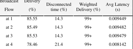
Figure 6 shows the delivery ratios for broadcast traffic from the XCom node. We observe very high packet delivery ratios (> 99.5%) at all receivers. Nodes 1 and 2 have superior performance than nodes 3 and 4 because the last two are exchanging heavy AB pair flows as well.
Figure 5: Situational awareness traffic: end-to-end latency Figure 6: Broadcast traffic from the XCom node intended for the remaining 4 nodes.
4.2 Snapshot Mobility Results
In this section, we report some simulation results for mobile network scenarios. Since we only had access to H matrices for the 5 waypoints shown in Figure 2, we could not simulate the effect of continual fading in a mobile network. Instead, we used a snapshot mobility model where all nodes dwell at particular waypoints for a constant amount of time and then switch to the next waypoint (in the clockwise direction) simultaneously. The node occupying the 6th waypoint in the
southernmost part of the loop is disconnected from the rest of the network.
Table 1: Situational Awareness flows under snapshot mobility AB Flow Delivery (%) Throughput (bits/sec) Avg Latency (s) Max Latency (s)
3->4 99.23 1488076 0.010979 0.027007 4->3 99.09 1486028 0.011108 0.032411 2->3 99.10 1485755 0.011147 0.027822 3->2 99.10 1485755 0.011312 0.035646 1->2 99.16 1486301 0.010930 0.030691 2->1 99.07 1484936 0.010886 0.023915
Table 2: Location triggered AB-pair flows under snapshot mobility
Broadcast Flow
Delivery
(%) Disconnected time (%) Delivery (%) Weighted Avg Latency (s)
at 1 85.55 14.3 99+ 0.009449 at 2 85.49 14.3 99+ 0.009482 at 3 85.53 14.3 99+ 0.009479 at 4 78.46 21.4 99+ 0.008142
Table 3: Xcom broadcast flow under snapshot mobility
4.3 Additional Observations
Since our MAC does not exchange RTS/CTS packets (due to additional delays in decoding), we are occasionally affected by the hidden terminal scenario. As mentioned in Section 3.2, our Channel Access scheme combines enhanced carrier sensing and randomized backoff before transmitting a stream of MIMO frames. In the free space propagation scenario, if the carrier sensing range can be made equal to twice the transmission range, then there will be no hidden terminals. However, in the Lakehurst test facility, this is not the case because the pathloss between three pairs of waypoints do not obey the triangle inequality; in other words, pl(A,C) (the path loss between nodes A and C) could be
greater than the sum of pl(A,B) and pl(B,C). In such circumstances, we depend on the randomized backoff process
which is a function of the “collision level indicator” (of the intermediate node) for reducing the probability of collision. Hence the amount of backoff and the number of frames per stream are important tunable parameters which need to be set carefully for achieving high throughput in the network. We analytically derived an expression for an appropriate contention backoff window size such that collision probability is minimized in a hidden terminal scenario.
Two nodes that are hidden from each other should pick a nominal contention window W such that if they backoff a random amount of time between 0 and W, their streams (of duration d<W) have a low probability of collision,
ε
. Suppose X and Y are uniformly distributed random variables between 0 and W (denoting respective starts of streams at hidden nodes), andβ
is the allowed overlap between two streams such that the underlying coding process protects from collisions. Solving for the case where the probability of collision probability is lower thanε
we get:ε β β
β = − = <
− | } 2 ( )2
Pr{| W d W d d Y
X and therefore
ε β − − = 1 1 d W .
Although multiple hidden terminals are much harder to provision for, we use the above as one of the guiding principles. One heuristic that we used was the following: when the contention-level indicator was k, then W is replaced by kW.
Other heuristics of backing off for integer multiples of W are more protective but sometimes a bit wasteful from a throughput standpoint. Analyzing such tradeoffs is a topic of future research.
Flow Delivery
% Disconnection Time (%) Delivery (%) Weighted Avg Latency (s) Max Latency (s)
5
CONCLUSIONS
MIMO technology promises to allow wireless communications devices to provide very high data rates in some of the worst environmental conditions. The best performing MIMO methods are the spatial-multiplexing modulation schemes such as Lucent’s V-BLAST. These algorithms’ high computational complexity places unique constraints and requirements on ad hoc MAC protocols if one is to maximize total channel throughput. In particular, MAC protocols which efficiently utilize such modulation schemes need to take into account the encoding and decoding delays, the variety of coding schemes depending upon the MIMO “mode,” the need for feedback and training, and fixed very long frame sizes.
In this paper we have described the design of a MIMO-MAC protocol which takes into account these realistic aspects of the MIMO modulation scheme. We believe it is the first such MAC protocol to do so and, additionally, has been implemented in both simulation and real platforms. This MAC lays the groundwork for taking full advantage of MIMO links in an ad hoc network and will hopefully provide inspiration and ideas for future MAC designers for MIMO.
6
REFERENCES
[Fosch98] G. J. Foschini. Layered Space-Time Architecture for Wireless Communication. Bell Labs Technical Journal, 6:311– 335, Mar. 1998.
[Gesb03] D. Gesbert, M. Shafi, D. Shiu, P. J. Smith, and A. Naguib. From Theory to Practice: An Overview of MIMO
SpaceTime Coded Wireless Systems. IEEE JSAC, 21(3):281–301, Apr 2003.
[Woln98] P. W. Wolniansky, G. J. Foschini, G. D. Golden, R. A. Valenzuela, V-BLAST: An Architecture for Realizing
Very High Data Rates Over the Rich-Scattering Wireless Channel , invited paper, Proc. ISSSE-98, Pisa, Italy,
Sept. 29, 1998.
[TradStudy] BBN Technologies, Mobile Network Mimo (MNM) MAC Tradeoff Analysis. Available on request.
[BoWi04] Boche, H.; Wiczanowski, M. Stability Region of Arrival Rates and Optimal Scheduling for MIMO-MAC -A
Cross-Layer Approach. In proceedings of International Zurich Seminar on Communications (IZS). February
18-20, 2004, Pages 18-21.
[JoBo03] Jorswieck, E.A.; Boche, H. Transmission strategies for the MIMO MAC with MMSE receiver: average MSE
optimization and achievable individual MSE region. In proceedings of IEEE Transaction on Signal Processing.
Volume 51, Issue 11, Nov 2003. Pages 2872 - 2881.
[SoUl05] Sosyal, A.; Ulukus, S. Asymptotic optimality of beamforming in multi-user MIMO-MAC with no orpartial CSI
at the transmitters. In proceedings Of Vehicular Technology Conference. Volume 3, May 30-June 1 2005. Pages
1619-1623.
[SuSi05] K. Sundaresan, R. Sivakumar Routing in Ad Hoc Networks with MIMO Links. In proceedings of ICNP, 2005. [MiJu05] Ming Hu; Junshan Zhang. MIMO medium access control and routing in ad hoc networks: a holistic
perspective. In proceedings of Workshop on High Performance Switching and Routing. May 12-14 2005. Pages
236 – 240.
[SuSiA03] K. Sundaresan and R. Sivakumar. On the Medium Access Control Problem in Ad-hoc Networks with Smart
Antennas. GNAN Research Group Technical Report, Georgia Institute of Technology, Apr 2003.
[ChKa04] Chao-Kai Wen; Kai-Kit Wong. Asymptotic spectral efficiency of spatially correlated MIMO multiple-access
channels with arbitrary signaling inputs for joint and separate decoding. In proceedings of International
Symposium on Information Theory, June 27-July 2 2004. Page 282.
[SuSiJ03] K. Sundaresan and R. Sivakumar. On the medium access control problems in ad-hoc networks with smart
antennas. In proceedings of ACM SIGMOBILE Mobile Computing and Communications Review, July 2003.