https://doi.org/10.5194/ars-15-249-2017
© Author(s) 2017. This work is distributed under the Creative Commons Attribution 3.0 License.
A 24 GHz Waveguide based Radar System using an Advanced
Algorithm for I/Q Offset Cancelation
Christoph Will1, Sarah Linz1, Sebastian Mann1, Fabian Lurz1, Stefan Lindner1, Robert Weigel1, and Alexander Koelpin2
1Institute for Electronics Engineering, Friedrich-Alexander-Universität Erlangen-Nürnberg, Cauerstr. 9, 91058 Erlangen, Germany
2Chair for Electronics and Sensor Systems, Brandenburg University of Technology, Siemens-Halske-Ring 14, 03046 Cottbus, Germany
Correspondence to:Christoph Will ([email protected])
Received: 23 December 2016 – Revised: 6 September 2017 – Accepted: 15 September 2017 – Published: 25 October 2017
Abstract.Precise position measurement with micrometer ac-curacy plays an important role in modern industrial applica-tions. Herewith, a guided wave Six-Port interferometric radar system is presented. Due to limited matching and disconti-nuities in the radio frequency part of the system, the design-ers have to deal with DC offsets. The offset voltages in the baseband lead to worse relative modulation dynamics relat-ing to the full scale range of the analog-to-digital convert-ers and thus, considerably degrade the system performance. While common cancelation techniques try to estimate and extinguish the DC offsets directly, the proposed radar sys-tem is satisfied with equalizing both DC offsets for each of the two differential baseband signal pairs. Since the complex representation of the baseband signals is utilized for a sub-sequent arctangent demodulation, the proposed offset equal-ization implicates a centering of the in-phase and quadrature (I/Q) components of the received signal, which is sufficient to simplify the demodulation and improve the phase accu-racy. Therefore, a standard Six-Port radar system is extended and a variable phase shifter plus variable attenuators are in-serted at different positions. An intelligent algorithm adjusts these configurable components to achieve optimal I/Q offset cancelation.
1 Introduction
A huge amount of automated processes in the modern indus-trial environment require accurate sensing technology for the surveillance of their working units. The type of the most
suit-able observation technique is dependent on its particular field of application. Nowadays, a lot of different distance sensors for linear movements have been published, like potentiomet-ric (Das et al., 2006), magnetostpotentiomet-rictive (Seco et al., 2005) or inductive principles (Fericean and Droxler, 2007), each of them with their specific advantages and disadvantages. An accurate radar system allegorizes another promising and convenient distance measurement system, since it facilitates contactless measurements. While in special use cases a free space propagation may be more expedient, primarily in in-dustrial environments a controlled wave propagation is pre-ferred, e.g., if one specific target shall be monitored. One possibility to enforce straightforward guidance of the electro-magnetic wave is ensured by using a parallel plate waveguide (Mann et al., 2014a, b), which is used for the proposed sys-tem.
compensation (Park et al., 2007). The proposed algorithm, in contrast, aims at removing the I/Q offset in the RF domain utilizing three variable attenuators and one variable phase shifter. This leads to an optimized usage of the dynamic range of the analog-to-digital converters if the adjusted base-band signal pairs are differentially sampled and appropriately amplified. Similar approaches were published in (Zhou et al., 2015) to cancel transmitter self-interference in the RF do-main for frequency-division duplexing and full-duplex wire-less applications and in (Boaventura et al., 2016) to suppress RF self-jamming in passive radio-frequency identification (RFID) systems. Since an I/Q offset cancelation also simpli-fies blind I/Q regeneration (Mailand and Richter, 2005), the proposed system concept can also be adapted and utilized for optimizing Six-Port based quadrature amplitude modulation (QAM) receivers.
2 Measurement Principle
The measurement principle of the proposed radar system is based on the Six-Port network. This technology was devel-oped in the 1970s by Engen and Hoer for power measure-ments (Engen and Hoer, 1972), and was converted to an al-ternative microwave receiver setup in recent years (Li et al., 1994; Koelpin et al., 2016). Within the Six-Port junction two input signals are superimposed with a static phase shift of π /2 among each other. In the proposed system a Wilkin-son power divider and a quadrature hybrid coupler are used as input components and two further hybrid couplers at the output. Four different output signals are generated, resulting from the quadrature phase shifts between the input signals, and subsequently down-converted by Schottky diodes. The absence of active components is an advantage of the Six-Port network considering power consumption and cost optimiza-tion compared to other radar setups.
Due to the quadrature phase shifts within the Six-Port net-work, the four baseband signalsB3.represent differential in-phase and quadrature components of a complex expression (Z):
Z=I+j Q=(B5−B6)+j (B3−B4) (1) The phase difference1σbetween the two input signals of the Six-Port network can easily be determined by subsequent arctangent demodulation:
1σ =argZ =arctan B
3−B4 B5−B6
(2) In a Six-Port radar system one input signal is supposed to be fed with the reference signal, which is a portion of the transmitted signal, while the other port is fed with the re-ceived signal. Therefore, changing the position of a reflecting target in propagation direction of the electromagnetic wave results in a variation of 1σ. Since the wavelengthλof the
PSG
T
Target
PPWG Six-Port
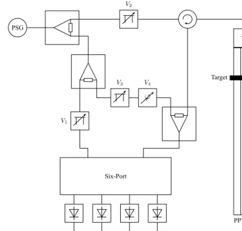
Figure 1.Six-Port transceiver system setup with three variable at-tenuators and one variable phase shifter.
signal source is known, it is possible to compute relative dis-tance changes1xbetween zero reference and the observed target:
1x=1σ
2π · λ
2 (3)
3 System Overview
In the proposed radar system a controlled wave propaga-tion is ensured by using a matched parallel plate waveguide (PPWG) instead of a common horn or patch antenna for free space propagation. The bidirectional coupling structure, called transition (T), is located at the top on the right of the block diagram illustrated in Fig. 1. In the upper left corner the signal source (PSG) is connected to a power splitter. Dur-ing the presented measurements a microwave vector signal generator (Keysight E8267D PSG) was used to generate well defined signals, but for miniaturization it can be replaced by a phase-locked loop (PLL) with a voltage controlled oscil-lator (VCO). The frequency was set to 24.0 GHz and all RF components of the PCB were appropriately matched.
path and transition as well as transition and receive path. The significant difference compared to common Six-Port radar systems, where the passive Six-Port network is directly fed by reference and received signal, is constituted by an addi-tional compensation path between the two Six-Port inputs. This path is integrated through two symmetrical Wilkinson power dividers, at which one of them is used as splitter and the other as combiner. The offset compensation is realized with two voltage controlled components: an adjustable at-tenuator (V3) and a variable phase shifter (V4). Hereby, the reflections of the signal to be transmitted at the waveguide transition shall be canceled out of the signal in the receive path. For this purpose a superposition with the reference sig-nal having correct amplitude and phase is necessary. Also the power in the reference path can variably be attenuated by control voltageV1.
The delivered baseband signals are sampled with four 12-bit analog-to-digital converters which are integrated in the In-fineon XMC4500 microcontroller. The digitized data is sent to a personal computer using Ethernet where further sig-nal processing is applied and the measured data gets visu-alized. The software additionally controls the voltages fed to the variable components by appropriately setting digital-to-analog converters with a resolution of 16 bit. To generate measurement data, a reflecting target is moved above the par-allel plate waveguide along the propagation direction of the electromagnetic wave by utilizing a linear stage which is also controlled by software. The movable target is an aluminum slider acting as a sliding short for the waveguide, which is used within the I/Q offset cancelation as well as for the sub-sequent verification measurements presented in Sect. 5.
4 I/Q Offset Cancelation
Every position of the target on top of the waveguide can be assigned to a particular complex number in I/Q or phase and absolute value representation. A linear motion of the target over a distance of λ/2 ideally produces a circle around the origin in the complex plane, hereinafter called projection. Due to nonidealities in the RF part, however, the measured projection is neither centered nor circular, but rather an offset ellipse, like MS1 in Fig. 5, induced by nonorthogonal base-band signals with individual offsets. The presented algorithm with four major steps has been developed to extinguish the I/Q offset by adjusting the four voltage controlled compo-nents. An orthogonalization of the elliptical shape had been investigated in preliminary experiments which yield best re-sults by minimizing the I/Q offset. Furthermore, several al-gorithms for estimating and reconstructing elliptic I/Q repre-sentations have already been published (Singh et al., 2013; Zakrzewski et al., 2014; Linz et al., 2014).
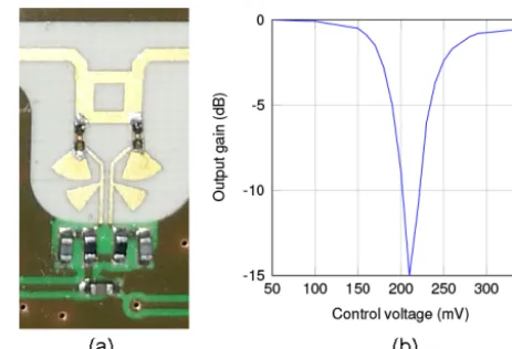
The variable attenuators are custom designs, which are each realized by a coupler and two diodes. Exemplarily, the PCB realization of the attenuator in the transmit path as
Figure 2. (a)PCB realization and(b) characteristic curve of the variable attenuator in the transmit path of the radar system.
well as its measured characteristic curve are illustrated in Fig. 2. Due to their identical design, the other attenuators have the same characteristics. The adjustable range of the control voltage is defined between 0 and 1.1 V, in which 0 V implicates no attenuation. Increasing the voltage up to ap-proximately 200 mV implies higher attenuation, respectively, a lower output gain. Further increasing the control voltage results in decreasing the attenuation. At the upper bound-ary of the voltage range the attenuation is still below 0 dB, wherefore control voltages between 0 and 200 mV are used to provide a large attenuation range. As default value all attenuators are fed with 0 V to guarantee minimal attenua-tion at the beginning of the cancelaattenua-tion algorithm. A Hittite HMC933 was used as variable phase shifter with a constant pre-amplification of the control voltage. The resulting volt-age range is valid within 0.0. . .2.0 V to shift the phase along a range larger than 2π. The dependency of the phase shift on its control voltage is also monotonic, but not linear. Exact values of intermediate control voltages are omitted in the fol-lowing since they are heavily dependent on the start position of the target, its motion range in each calibration sub-step, the target’s characteristics, and the particular hardware due to manufacturing tolerances.
4.1 Step 1: Optimizing transmission power
In the case of exceeding power in the receive path in com-parison to the reference path a cancelation of the I/Q offset is not possible by only adjusting the compensation path. How-ever, decreasing the transmitting power implies a decreased signal-to-noise ratio (SNR), for which reason it is necessary to preliminary optimize the power in the transmit path. This is realized by an unequally splitting Wilkinson power divider and a subsequent variable attenuator.
attenu-ation in the compensattenu-ation path by adjusting V3reduces the size of this ellipse while its origin remains constant. Hence, if the origin is not located within this ellipse, a compensation of the reflected signal is not possible and the total power in the receive path has to be reduced. This is achieved by increas-ing V2step-wise, whereby the ellipse in the complex plane generated by sweeping the variable phase shifter is centered regarding the complex origin. Due to the nonlinear character-istics of the voltage controlled attenuators shown in Fig. 2, it is recommended to choose an adaptive step-size. For each setting ofV2the phase shifter has to be repeatedly swept to check if the complex origin is positioned within this ellipse, which is the stop criterion for the first step of the proposed algorithm. Five to eight phase settings per optimization sub-step proved sufficient in practice as well as adjustingV2by using the mean of the current voltage and the corresponding control voltage for maximal attenuation for the next sub-step. Nevertheless, there is a trade-off between effort and preci-sion regarding the step-size of V2and the number of phase shifter settingsV4. Finally, the desired transmitting power of the radar system can be optimally adjusted by increasing the output power of the PSG.
4.2 Step 2: Optimizing power in reference path
For an optimization of the measurement accuracy the com-plex projection caused by a moving target has to be maxi-mized. During test measurements this was achieved by equal-izing the signal power at the Six-Port inputs. Therefore, the power in the reference path potentially has to be attenuated by increasing V1. This step is only reasonable if a target is repeatedly moving along a distance of at leastλ/2 to ensure the full valid phase of the complex representation is utilized. This is not mandatory for I/Q offset cancelation and it is skipped for time duration optimization or if the algorithm is processed with a stationary target. Though, if the attenuation in the reference path is changed, the position of the projec-tion may change and a validaprojec-tion iteraprojec-tion of the first step is required. Furthermore, the two variable attenuators in the transmit and reference path can be utilized as an automatic gain control (AGC) during running operation.
4.3 Step 3: Adaptive I/Q offset cancelation
This step is the major part of the proposed algorithm, in which the projection of a moving target is centered in the complex plane in a fast and precise way. The initial settings include the previously determined control voltagesV1andV2 for the variable attenuators as well as the optimal setting of the variable phase shifterV4where the projection was closest to the complex origin after succeeding the first step of the al-gorithm. Since the origin of the complex plane is now assured to be located within the ellipse generated by sweeping the variable phase shifter, increasing the attenuation in the com-pensation path (V3) causes a shift of the projection toward
the origin. This induces the assumption of an orthogonal be-havior amongV3andV4for a small complex area around the current projection, which was confirmed in practice and is utilized in this optimization step. The resulting line of mean values of the temporary projections produced by sweeping one of the two control voltages is hereinafter called search line. Since this assumption is only coarsely valid and due the nonconstant phase characteristics of variable attenuators, the phase of the attenuated compensating signal is also changed after optimizing its amplitude, which is why a subsequent phase adjustment (V4) is necessary again. These two sub-steps are continuously repeated until the distance between the mean of a measurement row and the complex origin is below a predefined threshold. During both kind of sub-steps several iterations of an infinite loop are executed to obtain a temporary optimum after each sub-step. The latest temporary optimum separates the search line into two search half-lines, whereupon the one closer to the complex origin is used for optimization.
(a)
(b)
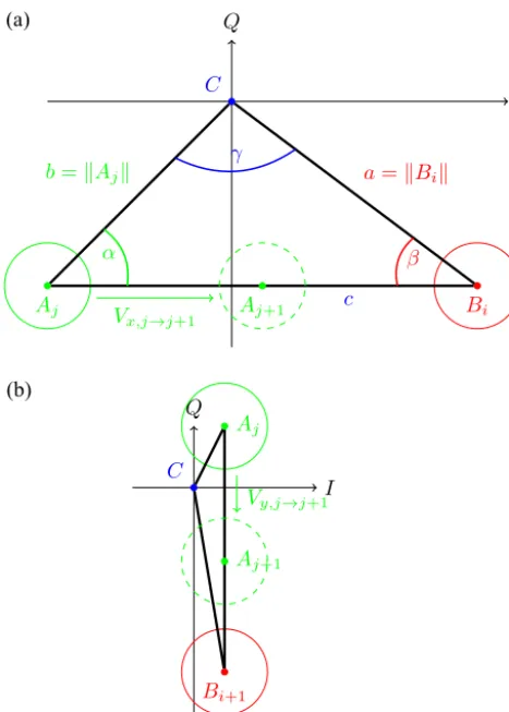
Figure 3.In plot(a)the mean value of the current temporary pro-jection (Aj), the mean value of the latest temporary optimum (Bi) and the complex origin (C) span a triangle whose interior angles are evaluated in the major part of the compensation algorithm. The last two iterations (jandj+1) of the current sub-stepito optimize Vxare shown. The temporary projectionAj+1is declared as new temporary optimumBi+1for the subsequent sub-step as depicted in plot(b). Here, the other control voltageVyis optimized.
The length of one side of the triangle can be calculated by the lengths of the other sides and the size of the opposite interior angle, applying the law of cosines (Bronstein et al., 2012). For the length of the segmentawhich represents the Euclidean norm of the mean value of the latest temporary optimum (kBik) the following equation is valid:
a2=b2+c2−2bccosα (4)
Respectively, Eq. (5) is valid for the Euclidean normbof the mean value of the current temporary projection Aj
.
b2=a2+c2−2accosβ (5)
Since these two segments are measured, respectively al-ready known, at the beginning of every iteration, these
equa-Start of iteration
2
1 3
4 5 6
End of iteration
Figure 4.The main decision logic determines the step size and search direction for the subsequent iteration for every sub-step within the core process (step 3) of the proposed algorithm. The il-lustrated flow chart is valid for both control voltages (V3andV4).
tions can be transformed to Eqs. (6) and (7). cosα=b
2+c2−a2
2bc (6)
cosβ=a
2+c2−b2
2ac (7)
The required anglesαandβare obtained by subsequently applying the inverse cosine function. The iterative evaluation of the angles is utilized in both kinds of sub-steps for alter-nately optimizingV3andV4. This infinite optimization loop is stopped if either two consecutive sub-steps do not further decrease the Euclidean norm of the projection mean or the step size is below a predefined threshold. Additionally, a pre-defined Euclidean norm for an optimal projection mean can be integrated as another stop criterion.
Both sub-steps use the same angle evaluation based deci-sion logic to determine the step size and search direction of the next iteration, illustrated as a flow chart in Fig. 4. The initial state Start of Iteration represents the adjustment of the control voltages followed by measuring of a new temporary projectionAj. Afterward, the interior angles of the complex triangle in Fig. 3a are calculated to determine the control voltage setting for the next iteration. The evaluation ofβand αleads to six cases which are described in detail below. In Fig. 4 a fixed margin ofπ/2 for both angle analyses is only depicted to simplify the graphical representation. In practice a tolerance of±0.03·πproved suitable and was implemented to easier achieve the cases (1) and (4).
optimum cannot further be improved in this sub-step, which is why the iteration loop is stopped and the other control voltage is optimized.
2. The current temporary projection is located on the cor-rect search half-line. The adjustment of the step size is determined by the value ofα and executed within the cases (4) to (6).
3. The temporary projection is located on the wrong search half-line. This is fixed by inverting sign of the control voltage step which leads to a temporary projection on the correct search half-line in the next iteration. 4. The search direction is orthogonal to the line between
the mean value of the temporary projection and complex origin. The loop is stopped and the current projection is declared as new temporary optimum.
5. If that case occurs at the first evaluation ofαwithin a sub-step, the initial step size is too small. Instead of re-ducing the step size for the next iteration, that value is added to the current step size every loop iteration, and additionally, a flag is set. Alternatively, the optimum case (4) was passed by continuously decreasing the step size in case (6). In this sub-case the loop is stopped and either the current or previous projection is declared as new temporary optimum.
6. This is the default case of the proposed algorithm, in which a new temporary optimum is searched by ap-proaching temporary projections toward the current op-timum. The decreasing step size is realized by multi-plying it with a predefined factor smaller than 1. If the new step size below its predefined lower limit or if the flag was set in case (5), the loop is stopped. An active flag indicates the pass of the optimal case (4) while lin-early increasing the step size by consecutive executions of case (5).
The bottom state End of Iteration depicts a placeholder, too. If a new temporary optimum was declared (initial, pre-vious or current projection), the infinite loop is stopped, and otherwise, a new iteration is executed. In case of a new opti-mum a new sub-step is started to optimize the other control voltage. If two consecutive sub-steps do not further improve the current temporary optimum, or if the step sizes of both control voltages are below their predefined lower limit, step 3 is finished.
4.4 Step 4: Fine-tuning of compensation path
After completion of the previous step the origin of the com-plex plane is located within the temporary projection, consid-ering a moving target during the past measurements. In this final step a subsequent fine-tuning minimizes the remaining
offset of the complex projection down to a predefined preci-sion if a moving target is utilized. Otherwise, the fine-tuning is dispensable and can be skipped.
The procedure of the final step is once more based on the assumption that the resulting search directions by adjusting V3andV4are orthogonal, which, in practice, proved quite ac-curate for small modifications. Within an infinite loop both control voltages are alternately and repeatedly adjusted in both search directions with a very fine step size. In practice, this causes two shifts of the projection in opposite directions. Considering these temporary projections as well as the cur-rent optimum, the one with the smallest Euclidean norm is chosen as new optimum and afterward, the other control volt-age is optimized. If both control voltvolt-ages subsequently do not have to be readjusted, the final optimum is detected and the infinite optimization loop is stopped.
5 Measurement Results
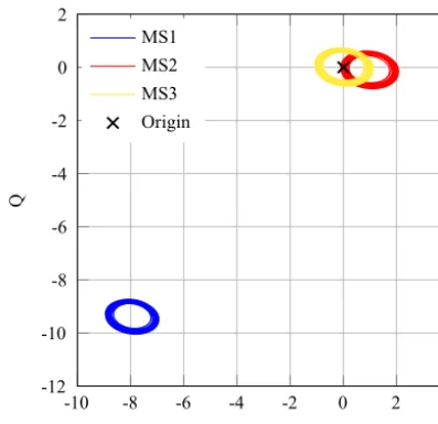
Three measurement setups were validated to prove the func-tionality of the proposed algorithm and the resulting perfor-mance enhancement of the radar system. In the first setup (MS1) data was measured without utilizing the cancelation algorithm and default values of 0 V for all control voltages were applied, which depicts an uncompensated system with a high I/Q offset acting as a benchmark in the following. In the second setup (MS2) the cancelation algorithm was com-pleted with a fixed target, while in the third one (MS3) a target was moving along a distance ofλ/2 for each calibra-tion sub-step, which implies a phase rotacalibra-tion of 2π. During the offset cancelation of MS2 and MS3 the minimal con-trol voltage step size in step 3 and 4 of the algorithm were set to 1.0 mV. After obtaining optimal control voltages for each measurement setup a software controlled linear stage was used to move a target along a distance of 15 cm. A step size of 100 µm was used, and 1000 samples per target posi-tion were acquired. Exemplary projecposi-tions in the I/Q plane averaging all samples at each target position are illustrated in Fig. 5. Further signal processing was applied for these pro-jections to calculate relative distance values which are later utilized as a calibration. The remaining mean I/Q offset was subtracted for each projection first, and after a subsequent arctangent demodulation the relative distance was calculated by applying Eq. (3).
-10 -8 -6 -4 -2 0 2 4 -12
-10 -8 -6 -4 -2 0 2
I
Q
MS1 MS2 MS3 Origin
Figure 5.I/Q plot for measured data using a moving target over a distance of 15 cm on the waveguide for three different measurement setups.
2011). Thus, the importance of repeatability as a figure of merit increases, which is typically analyzed by evaluating the standard deviation at each calibration point. Here, the stan-dard deviation is evaluated using 1000 samples per target po-sition along the complete measurement range. The resulting curves for each measurement setup is depicted in Fig. 6a A second measurement data set was acquired for each setup to verify the achieved enhancement regarding the repeatability by calculating the relative error. One distance value per target position was acquired, calculated and compared to the cali-bration data. The resulting relative errors for each measure-ment setup are illustrated in Fig. 6b, and their distributions are depicted in Fig. 6c as histograms.
Contemplating the figures in this section, the benefit of the proposed algorithm can easily be perceived. The standard de-viation as well as the relative error is significantly smaller af-ter applying the I/Q offset cancelation algorithm. The charac-teristics after running the cancelation algorithm using a fixed target (MS2) are almost as good as using a moving target (MS3). In both measurement setups the resulting relative er-ror is lower than 10 µm along most part of the evaluated dis-tance.
6 Discussion
A comparison to other radar systems with integrated error compensation is barely feasible, since state-of-the-art sys-tems either suppress DC offsets in hardware (Namgoong and Meng, 2001; Park et al., 2007; Salamin et al., 2014) or can-cel the TX leakage by improving the TX-to-RX isolation by fixed, passive circuitries (Lee et al., 2011; Kim et al., 2004, 2007) instead of algorithmically removing the I/Q offset by
0 0.05 0.10 0.15
0 2 4 6 8 10
Distance (m)
Standard
de
viation
(µm)
MS1 MS2 MS3
(a)
'LVWDQFH P
(UURU
P
06 06 06
E
(UURU P
2FFXU
DQFH
06 06 06
F
adjusting variable RF components. Furthermore, (Namgoong and Meng, 2001) provides an exemplary system design with DC offset suppression but no measurements and (Park et al., 2007; Salamin et al., 2014; Lee et al., 2011) solely present the achieved improvements on the final measurement values re-garding their specific application case. Common TX leakage cancelers (Kim et al., 2004, 2007) compare the increase of the TX-to-RX isolation, but an insufficient isolation is only one of various RF impairments which induce measurement errors. Finally, the aim of the proposed system setup is not to completely cancel any error source, but to equalize particu-lar DC offsets in the baseband by minimizing the I/Q offset. While DC offsets are still remaining even after running the optimization algorithm, a subsequent differential sampling of the adjusted baseband signal pairs along with an appropri-ate amplification leads to an increased used dynamic range of the analog-to-digital converters. Therefore, only a com-parison to the system presented in (Mann et al., 2014b) is reasonable regarding the measurement error, which formed the basis of the proposed system setup. The system in (Mann et al., 2014b) likewise consists of a waveguide based Six-Port microwave interferometer, while a linear stage is used as well for target positioning with an accuracy of 0.5 µm and four 12-bit single-ended analog-to-digital converters for dig-itization. However, there are no variable attenuators or phase shifters integrated for leakage cancelation or error compen-sation in contrast to the proposed RF system design. Com-paring the error curves in Fig. 6b and c with the correspond-ing measurement results in (Mann et al., 2014b) yields two oppositional outcomes. On the one hand the system perfor-mance decreases if the proposed system resides in a worst case operating point (MS1), e.g., by a resulting duplication of the relative error. After running through the presented I/Q offset cancelation algorithm on the other hand, the relative error of the measurement system is approximately halved in comparison to (Mann et al., 2014b). Additionally, a standard deviation with less than 3 µm, if residing in a compensated operating point (MS2 or MS3), is considerably low.
Due to long term instabilities, which are mostly caused by temperature dependent components, the radar system has to be calibrated regularly. In such a case the processing time of the compensation algorithm is essential. In comparison to the 20 s running time of the algorithm presented in (Zhang et al., 2010) the proposed I/Q offset compensation algorithm is considerably faster. In 20 test cycles it required 3.92 s at most to converge to an optimal operating point (MS3), assuming a sinusoidal test signal attached either to the waveguide tran-sition directly or to the back end of the waveguide. Even without such a test signal attached, a fast recalibration can be executed resulting in a semi-optimal operating point (MS2), which nonetheless implicates a higher system performance compared to (Mann et al., 2014b) as shown in the previ-ous section. Lowering the number of samples per measure-ment step the algorithm becomes more imprecise, but si-multaneously a further acceleration of the processing time
is achieved. The time span between necessary recalibrations to maintain a low measurement error is highly dependent on the used hardware components and the ambient variations as well as on further utilized signal processing routines for additional error compensation. In (Will et al., 2017b), e.g., a temperature compensation for radar based displacement measurements was proposed which could be applied in this measurement system after adaption.
7 Conclusions
A 24 GHz guided wave Six-Port radar system was presented in this paper. The system concept comprises a new I/Q offset cancelation algorithm which is executed by adjusting three voltage controlled attenuators and one voltage controlled phase shifter. Instead of directly eliminating the DC offsets of the baseband signals, the proposed system removes the projection offset in the complex plane. The functionality of the algorithm has been validated by measurements. Utilizing a target moving on the waveguide during cancelation pro-cess will achieve best results, but a calibration run with fixed target delivers nearly equal performance. Both measurement setups more than halve the standard deviation as well as the relative error in comparison to an uncompensated measure-ment setup.
Data availability. Underlaying data are available from the corre-sponding author upon request.
Author contributions. CW researched and implemented the pro-posed algorithm and wrote most parts of this publication. SL and SM developed the RF front end of the presented radar system. FL and SL developed the baseband printed circuit board, imple-mented the microcontroller program code and created the measure-ment setup. RW was the general advisor of this research group. AK was the project coordinator and an additional advisor.
Competing interests. The authors declare that they have no conflict of interest.
Special issue statement. This article is part of the special issue “Kleinheubacher Berichte 2016”. It is a result of the Klein-heubacher Tagung 2016, Miltenberg, Germany, 26–28 September 2016.
References
Ahn, B.-J., Kim, S.-K., and Yook, J.-O.: Isolation-improved branch-line coupler based on feed-forward technique, in: 2005 Asia-Pacific Microwave Conference Proceedings, vol. 1, 4 pp., https://doi.org/10.1109/APMC.2005.1606300, 2005.
AOlopade, A. O. and Helaoui, M.: High performance ho-modyne six port receiver using memory polynomial cal-ibration, in: 2014 IEEE 27th Canadian Conference on Electrical and Computer Engineering (CCECE), 1–4, https://doi.org/10.1109/CCECE.2014.6901127, 2014.
Boaventura, A., Santos, J., Oliveira, A., and Carvalho, N. B.: Perfect Isolation: Dealing with Self-Jamming in Pas-sive RFID Systems, IEEE Microw. Mag., 17, 20–39, https://doi.org/10.1109/MMM.2016.2600942, 2016.
Bronstein, I. N., Hromkovic, J., Luderer, B., Schwarz, Ha.-R., Blath, J., Schied, A., Dempe, S., Wanka, G., and Gottwald, S.: Taschenbuch der Mathematik, vol. 1, Springer-Verlag, 2012. Das, A., Bhadri, P., Beyette, F., Jang, A., Bishop, P., and
Tim-mons, W.: A Potentiometric Sensor System with Integrated Cir-cuitry for in situ Environmental Monitoring, in: Nanotechnology, 2006, IEEE-NANO 2006, Sixth IEEE Conference on, 2, 917– 920, https://doi.org/10.1109/NANO.2006.247810, 2006. Engen, G. F. and Hoer, C. A.: Application of an Arbitrary 6-Port
Junction to Power-Measurement Problems, IEEE T. Instrum. Meas., 21, 470–474, https://doi.org/10.1109/TIM.1972.4314069, 1972.
Fericean, S. and Droxler, R.: New Noncontacting Inductive Analog Proximity and Inductive Linear Displacement Sen-sors for Industrial Automation, IEEE Sens. J., 7, 1538–1545, https://doi.org/10.1109/JSEN.2007.908232, 2007.
Kim, C.-Y., Kim, J.-G., and Hong, S.: A Quadrature Radar Topology With Tx Leakage Canceller for 24-GHz Radar Applications, IEEE T. Microw. Theory, 55, 1438–1444, https://doi.org/10.1109/TMTT.2007.900316, 2007.
Kim, J.-G., Ko, S., Jeon, S., Park, J.-W., and Hong, S.: Balanced topology to cancel Tx leakage in CW radar, IEEE Microw. Wirel. Co., 14, 443–445, https://doi.org/10.1109/LMWC.2004.832080, 2004.
Koelpin, A., Lurz, F., Linz, S., Mann, S., Will, C., and Lindner, S.: Six-Port Based Interferometry for Precise Radar and Sensing Applications, Sensors, 16, 1556, https://doi.org/10.3390/s16101556, 2016.
Lee, H. L., Lim, W.-G., Oh, K.-S., and Yu, J.-W.: 24 GHz Balanced Doppler Radar Front-End With Tx Leak-age Canceller for Antenna Impedance Variation and Mu-tual Coupling, IEEE T. Antenn. Propag., 59, 4497–4504, https://doi.org/10.1109/TAP.2011.2165486, 2011.
Li, J., Bosisio, R., and Wu, K.: A six-port direct dig-ital millimeter wave receiver, in: Microwave Sym-posium Digest, 1994, IEEE MTT-S, 3, 1659–1662, https://doi.org/10.1109/MWSYM.1994.335122, 1994.
Linz, S., Vinci, G., Lindner, S., Mann, S., Lurz, F., Barbon, F., Weigel, R., and Koelpin, A.: I/Q imbalance compensa-tion for Six-port interferometers in radar applicacompensa-tions, in: Eu-ropean Microwave Conference (EuMC), 2014 44th, 746–749, https://doi.org/10.1109/EuMC.2014.6986542, 2014.
Mailand, M. and Richter, R.: Blind IQ-Regeneration for Six-Port-Based Direct Conversion Receiver with Low Analog Complex-ity, in: Wireless Conference 2005 – Next Generation Wireless and Mobile Communications and Services (European Wireless), 11th European, 1–7, 2005.
Mann, S., Lindner, S., Barbon, F., Linz, S., Talai, A., Weigel, R., and Koelpin, A.: A tank level sensor based on Six-Port technique comprising a quasi-TEM waveguide, in: Wireless Sensors and Sensor Networks (WiSNet), 2014 IEEE Topical Conference on, 4–6, https://doi.org/10.1109/WiSNet.2014.6825512, 2014a. Mann, S., Lindner, S., Lurz, F., Barbon, F., Linz, S., Weigel, R.,
and Koelpin, A.: A microwave interferometer based contactless quasi-TEM waveguide position encoder with micrometer accu-racy, in: Microwave Symposium (IMS), 2014, IEEE MTT-S, 1– 4, https://doi.org/10.1109/MWSYM.2014.6848655, 2014b. Namgoong, W. and Meng, T.: Direct-conversion RF
receiver design, IEEE T. Commun., 49, 518–529, https://doi.org/10.1109/26.911459, 2001.
Park, B.-K., Boric-Lubecke, O., and Lubecke, V.: Arctangent Demodulation With DC Offset Compensation in Quadrature Doppler Radar Receiver Systems, IEEE T. Microw. Theory, 55, 1073–1079, https://doi.org/10.1109/TMTT.2007.895653, 2007. Salamin, Y., Pan, J., Wang, Z., Tang, S., Wang, J., Li, C.,
and Ran, L.: Eliminating the Impacts of Flicker Noise and DC Offset in Zero-IF Architecture Pulse Com-pression Radars,IEEE T. Microw. Theory, 62, 879–888, https://doi.org/10.1109/TMTT.2014.2307832, 2014.
Seco, F., Martin, J. M., Jiménez, A. R., and Calderón, L.: A high ac-curacy magnetostrictive linear position sensor, Sensor. Actuator. A Phys., 123, 216–223, 2005.
Singh, A., Gao, X., Yavari, E., Zakrzewski, M., Cao, X. H., Lubecke, V. M., and Boric-Lubecke, O.: Data-Based Quadrature Imbalance Compensation for a CW Doppler Radar System, IEEE T. Microw. Theory, 61, 1718–1724, https://doi.org/10.1109/TMTT.2013.2249525, 2013.
Vinci, G., Barbon, F., Weigel, R., and Koelpin, A.: A novel, wide angle, high resolution Direction-Of-Arrival detector, in: 2011 8th European Radar Conference, 265–268, 2011.
Vinci, G., Lindner, S., Barbon, F., Weigel, R., and Koelpin, A.: Promise of a Better Position, IEEE Microw. Mag., 13, S41–S49, https://doi.org/10.1109/MMM.2012.2216710, 2012.
Will, C., Linz, S., Mann, S., Lurz, F., Lindner, S., Weigel, R., and Koelpin, A.: Segmental polynomial approxima-tion based phase error correcapproxima-tion for precise near field displacement measurements using Six-Port microwave interferometers, in: 2017 IEEE Topical Conference on Wireless Sensors and Sensor Networks (WiSNet), 23–25, https://doi.org/10.1109/WISNET.2017.7878746, 2017a. Will, C., Mann, S., Michler, F., Reissland, T., Lurz, F., Weigel, R.,
and Koelpin, A.: Error Compensation of the Temperature In-fluence on Radar Based Displacement Measurements, in: 2017 IEEE Asia Pacific Microwave Conference (APMC), to be pub-lished, 2017b.
Zhang, Y., Li, Z., Jiao, T., Lv, H., and Wang, J.: Simulation research of microwave automatic clutter-cancellation in life-detection radar, in: Biomedical Engineering and Informatics (BMEI), 2010 3rd International Conference on, 5, 2098–2100, https://doi.org/10.1109/BMEI.2010.5640012, 2010.