Advances in Radio Science, 3, 27–37, 2005 SRef-ID: 1684-9973/ars/2005-3-27
© Copernicus GmbH 2005
Advances in
Radio Science
OFDM: From the Idea to Implementation
S. A. Fechtel
Infineon Technologies AG, Rosenheimer Str. 116, 81699 M¨unchen, Germany
Abstract. OFDM (orthogonal frequency-division
multiplex-ing) is one of the key digital communication technologies of the current decade. The first part of this paper presents the fundamentals of OFDM and its benefits in the presence of multipath propagation in a tutorial-like fashion. The second part details on some of the most important aspects of OFDM transceiver implementation: concept of receiver channel fil-tering and A/D conversion, radio impairment compensation (I/Q mismatch), and OFDM demodulator (FFT) design.
1 Introduction
The ever-increasing demand for very high-rate wireless data transmission calls for technologies which make use of the available electromagnetic resource in the most intelligent way. Key objectives are spectrum efficiency (bits per second per Hertz), robustness against multipath propagation, range, power consumption, and implementation complexity. These objectives are often conflicting, so techniques and implemen-tations are sought which offer the best possible tradeoff be-tween them.
Two of the most effective means of closing the gap be-tween the achieved performance and channel capacity are advanced channel coding (to combat noise) and OFDM mod-ulation (to combat multipath). In conjunction with advanced forward error correction (FEC) coding, e.g., turbo, spherical, or LDPC (low-density parity check) codes, advanced OFDM is the modulation of choice when it comes to improving ro-bustness against multipath - possibly fading – at reasonable cost of implementation. In order to improve spectral effi-ciency, the best strategy is to increase the capacity of the channel itself. This is effectuated by input multiple-output (MIMO) smart antenna systems which make use of the spatial dimension to essentially scale the data rate trans-ferred over the same channel bandwidth with the number of antennas. As MIMO systems have now become within reach of low-cost implementation in highly-integrated de-vices, they are currently a very active field of R&D activity and standardization.
Correspondence to: S. A. Fechtel ([email protected])
Combining several advanced technologies leads to partic-ularly attractive solutions. OFDM, which by now has ma-tured to an established technology, also serves as a solid ba-sis of many of the most recent R&D developments, in par-ticular MIMO. Figure 1 gives an overview of some impor-tant wireless communication standards and standardization efforts in terms of range and PHY (physical layer) data rate. OFDM and MIMO-OFDM are seen to play a key role in high-rate data transmission over wireless channels for a wide range of applications such as WLAN (wireless local-area net-works), DVB-T (terrestrial digital video broadcasting), and also UWB (ultra wideband).
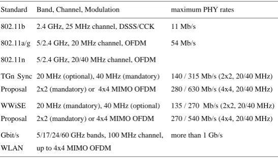
Concentrating on wireless LAN in this paper, Table 1 displays basic parameters of current and forthcoming IEEE WLAN standards. All standards but the very first (802.11b, 1...11 Mb/s) are based on OFDM. Currently, 802.11a/g-based devices are entering the mass market, offering PHY rates between 6 and 54 Mb/s. In the near future, 802.11n standardization will be finalized. The two most promising proposals are TGn Sync (task group n synchronization) and WWiSE (world-wide spectrum efficiency). TGn Sync pro-poses doubling the channel bandwidth to 40 MHz (rates up to 630 Mb/s), whereas WWiSE confines itself to 20 MHz chan-nels (40 MHz optional where permitted, then with rates up to 540 Mb/s) in order to obey current spectrum regulations. Both contending proposals improve MAC efficiency, and, more importantly, both are based on MIMO-OFDM tech-nology with between 2×2 and 4×4 TX and RX antennas. The latest development efforts for next-generation WLAN, e.g., the WIGWAM (wireless Gigabit with advanced multi-media support) project initiated in 2003, are targeting wide-band MIMO-OFDM (100 MHz channel in higher wide-bands up to 60 GHz) to attain scalable data rates well beyond 1 Gb/s.
28 S. A. Fechtel: OFDM: From the Idea to Implementation
3 data rate
10 kbit/s 100 kbit/s 1 Mbit/s 10 Mbit/s 100 Mbit/s 1 Gbit/s
range
10 m 100 m 1 km 10 km
UMTS
GSM
Blue-tooth DECT
Gbit/s WLAN
DVB-T
OFDM
WLAN 802.11a
WLAN 802.11b WLAN 802.11n
Figure 1.Wireless Communication Standards.
Figure 2. TypicalMultipath Radio Channel Impulse Response and Transfer Function
0 50 100 150 200 250 300 350 400 450 500
0 0.2 0.4 0.6 0.8 1
Time [ns]
Rela
ti
ve Power
-100 -80 -60 -40 -20 0 20 40 60 80 100
-40 -30 -20 -10 0
Frequency [MHz]
Pathloss [dB]
Fig. 1. Wireless Communication Standards.
Table 1. Basic Parameters of Wireless LAN Standards and Standard Proposals.
Table 1. Basic Parameters of Wireless LAN Standards and Standard Proposals Standard Band, Channel, Modulation maximum PHY rates 802.11b 2.4 GHz, 25 MHz channel, DSSS/CCK 11 Mb/s
802.11a/g 5/2.4 GHz, 20 MHz channel, OFDM 54 Mb/s 5/2.4 GHz, 20/40 MHz channel, OFDM
20 MHz (optional), 40 MHz (mandatory) 2x2 (mandatory) or 4x4 MIMO OFDM
140 / 315 Mb/s (2x2, 20/40 MHz) 280 / 630 Mb/s (4x4, 20/40 MHz) 802.11n
TGn Sync Proposal WWiSE Proposal
20 MHz (mandatory), 40 MHz (optional) 2x2 (mandatory) or 4x4 MIMO OFDM
135 / 270 Mb/s (2x2, 20/40 MHz) 270 / 540 Mb/s (4x4, 20/40 MHz) Gbit/s
WLAN
5/17/24/60 GHz bands, 100 MHz channel, up to 4x4 MIMO OFDM
more than 1 Gb/s
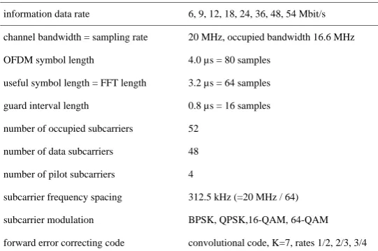
Table 2. WLAN Standard 802.11a/g: PHY Transmission Parameters information data rate 6, 9, 12, 18, 24, 36, 48, 54 Mbit/s channel bandwidth = sampling rate 20 MHz, occupied bandwidth 16.6 MHz OFDM symbol length 4.0 µs = 80 samples
useful symbol length = FFT length 3.2 µs = 64 samples guard interval length 0.8 µs = 16 samples number of occupied subcarriers 52
number of data subcarriers 48 number of pilot subcarriers 4
subcarrier frequency spacing 312.5 kHz (=20 MHz / 64) subcarrier modulation BPSK, QPSK,16-QAM, 64-QAM forward error correcting code convolutional code, K=7, rates 1/2, 2/3, 3/4
2 Fundamentals of OFDM
Wireless communication usually deals with multipath radio channels. The time- and frequency domain representations of a typical channel realization are shown in Fig. 2. The baseband-equivalent channel impulse responseh(τ;t ) and transfer functionH (f;t )both characterize the instantaneous channel state at timet, where the impulse response is formed by superposition of a (possibly large) number of reflected or scattered multipath rays with distinct (complex-valued) gains
ci(t )and delaysτi(t ). Naturally, the gains tend to become smaller as the path delay rises, and the set of “relevant” paths with gainci(t )above a certain significance level (depending on the required signal-to-noise ratio for the particular link) determines the effective spanτmaxof the multipath channel.
Wideband transmission channels used in high-rate com-munications are often strongly frequency-selective (lower part of Fig. 2), rendering conventional equalization difficult,
S. A. Fechtel: OFDM: From the Idea to Implementation 29
3
data rate
10 kbit/s 100 kbit/s 1 Mbit/s 10 Mbit/s 100 Mbit/s 1 Gbit/s
range
10 m 100 m 1 km 10 km
UMTS
GSM
Blue-tooth DECT
Gbit/s WLAN
DVB-T
OFDM
WLAN 802.11a
WLAN 802.11b WLAN 802.11n
Figure 1.
Wireless Communication Standards.
Figure 2. Typical
Multipath Radio Channel Impulse Response and Transfer Function
0 50 100 150 200 250 300 350 400 450 500
0 0.2 0.4 0.6 0.8 1
Time [ns]
Rela
ti
ve Power
-100 -80 -60 -40 -20 0 20 40 60 80 100
-40 -30 -20 -10 0
Frequency [MHz]
Pathloss [dB]
Fig. 2. Typical Multipath Radio Channel Impulse Response and Transfer Function.
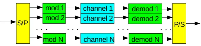
4 Figure 3. Parallel Transmission over Smallband Subchannels
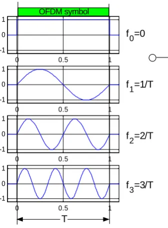
Figure 4. OFDM Symbol: Orthogonal Subcarrier Waveforms
S/P
channel 1
channel 2
channel N
P/S
demod 1
demod 2
demod N
. . .
. . .
. . .
mod 1
mod 2
mod N
. . .
0 0.5 1
-1 0 1
0 0.5 1
-1 0 1
0 0.5 1
-1 0 1
0 0.5 1
-1 0 1
T
f =0
0
f =1/T
1
f =2/T2
f =3/T3
-3 -2 -1 0 1 2 3 4 5 6
0 0.5 1
-3 -2 -1 0 1 2 3 4 5 6
0 0.5 1
-3 -2 -1 0 1 2 3 4 5 6
0 0.5 1
1/T transmitted
channel
received
OFDM symbol
Fig. 3. Parallel Transmission over Smallband Subchannels.
Figure 4 illustrates OFDM transmission over a frequency-selective channel. In this simple example, the four sub-carrier waveforms are given by 0, 1, 2, and 3 full peri-ods of sinusoids within length T, respectively. An OFDM symbol is formed by modulating each of these subcarriers by a (complex-valued) PSK or QAM symbol and super-pose the resulting modulated waveforms. The corresponding frequency-domain signals (right-hand side of Fig. 4) exhibit a sin(x)/x-characteristic with center frequencies 0, 1/T, 2/T
and 3/T, respectively. At these frequencies, all but one wave-form are seen to have zero crossings, so they are mutually orthogonal. Given a sufficiently large number of subnels, thus small subcarrier bandwidth relative to the chan-nel coherence bandwidth, the use of OFDM effectively con-verts a frequency selective channel into an orthogonal set of frequency-flat subchannels.
Beyond orthogonality, a second ingredient is required in making OFDM symbols robust against multipath, viz., the
guard interval. Figure 5 illustrates the insertion of a guard interval and the effect of multipath on a so-formed OFDM symbol. The guard interval of lengthTgis given by the cyclic extension at the beginning of an OFDM symbol (left-hand side of Fig. 5), its samples are taken from the latter section of the (original) OFDM symbol. Hence, the total OFDM symbol length increases toT+Tg. The associated loss in transmission efficiencyT /(T+Tg)is greatly outweighted by the benefits in the presence of multipath, as illustrated by the right-hand side of Fig. 5: at the channel output (here two-ray), delayed and weighted copies of the waveform (the one with frequency 1/T is shown as an example) are superim-posed. Therefore, the received waveforms exhibit disconti-nuities at the (delayed) borders between consecutive OFDM symbols. However, as long as the span of channel delays
30 S. A. Fechtel: OFDM: From the Idea to Implementation
4
Figure 3. Parallel Transmission over Smallband Subchannels
Figure 4. OFDM Symbol: Orthogonal Subcarrier Waveforms
S/P
channel 1
channel 2
channel N
P/S
demod 1
demod 2
demod N
. . .
. . .
. . .
mod 1
mod 2
mod N
. . .
0 0.5 1
-1 0 1
0 0.5 1
-1 0 1
0 0.5 1
-1 0 1
0 0.5 1
-1 0 1
T
f =00
f =1/T1
f =2/T2
f =3/T3
-3 -2 -1 0 1 2 3 4 5 6
0 0.5 1
-3 -2 -1 0 1 2 3 4 5 6
0 0.5 1
-3 -2 -1 0 1 2 3 4 5 6
0 0.5 1
1/T transmitted
channel
received
OFDM symbol
Fig. 4. OFDM Symbol: Orthogonal Subcarrier Waveforms.
Figure 5. OFDM Symbol: Guard Interval
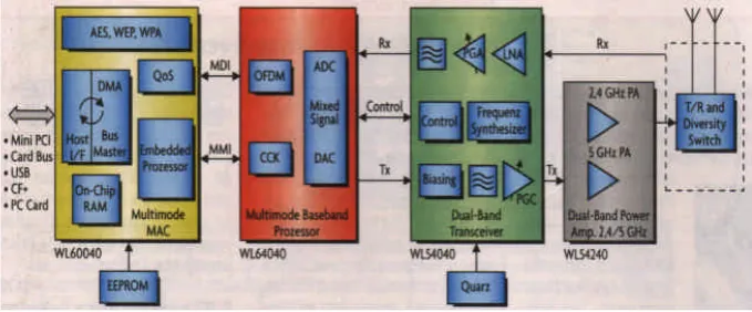
Figure 6. 802.11a/b/g Dual-Band WLAN Transceiver
0 0.5 1
-1 0 1
0 0.5 1
-1 0 1
0 0.5 1
-1 0 1
0 0.5 1
-1 0 1
T
f =00
f =1/T1
f =2/T2
f =3/T3
Tg
guard interval insertion: cyclic extension
0 0.5 1
-1 0 1
0 0.5 1
-1 0 1
0 0.5 1
-1 0 1
0 0.5 1
-1 0 1
T
useful signal window
τ
Tg
guard interval elimination
a1
a 2
τ
0
h(τ)
Fig. 5. OFDM Symbol: Guard Interval.
the amplitude-weighted and phase-shifted versions of their original counterparts. The orthogonality property of the orig-inal OFDM symbol is thus restored, which implies both or-thogonality in time (no intersymbol interference, ISI) and in frequency (no intercarrier interference, ICI). As a conse-quence, equalization in the subcarrier domain becomes par-ticularly simple: the remaining amplitude and phase distor-tion (or, equivalently, the complex-valued gain factor) affect-ing each subcarrier can be easily corrected for, e.g., by com-plex division or demapping.
3 OFDM Transceiver Implementation
S. A. Fechtel: OFDM: From the Idea to Implementation 31
5 Figure 5. OFDM Symbol: Guard Interval
Figure 6. 802.11a/b/g Dual-Band WLAN Transceiver
0 0.5 1 -1
0 1
0 0.5 1 -1
0 1
0 0.5 1 -1
0 1
0 0.5 1 -1
0 1
T
f =0
0
f =1/T1
f =2/T2
f =3/T3
Tg
guard interval insertion: cyclic extension
0 0.5 1 -1
0 1
0 0.5 1 -1
0 1
0 0.5 1 -1
0 1
0 0.5 1 -1
0 1
T useful signal window
τ
T
g
guard interval elimination
a1
a2
τ 0
h(τ)
Fig. 6. 802.11a/b/g Dual-Band WLAN Transceiver.
6 Figure 7. WLAN OFDM Baseband and RF PHY Transceiver Architecture
Figure 8. Low-IF Receiver Channel Filtering and A/D Conversion
-40 -30 -20 -10 0 10 20 30 40
-60 -50 -40 -30 -20 -10 0
Low IF Analog Filter Response
gain [dB]
-40 -30 -20 -10 0 10 20 30 40
-90 -80 -70 -60
Low IF Spectrum Mask
le
vel [dBm]
desired signal interference noise floor
-0.5 -0.4 -0.3 -0.2 -0.1 0 0.1 0.2 0.3 0.4 0.5 -100 -95 -90 -85 -80 -75 -70
Low IF Filtered/Aliased Spectrum
frequency
le
vel [dBm]
sampled desired signal sampled interference aliasing noise floor IF TX 6...54 Mb/s input 6...54 Mb/s output PA low-IF upcon-version LO from MAC scrambler convol. encoder interleaver QAM modulator IFFT guard interval insertion low-IF upconversion TX IQ/DC compensation
20 MHz -> 80 MHz center 0 -> 10 MHz
DAC DAC low-IF signal ADC ADC low-IF signal low-IF filtering + downcon-version preamble detection timing/frequency sync guard removal FFT channel estimation subcarrier equalization deinterleaver Viterbi decoder to
MAC IF filter PGA PGA low-IF downcon-version LO LNA
80 MHz -> 20 MHz center 10 MHz -> 0
1
2
3
Fig. 7. WLAN OFDM Baseband and RF PHY Transceiver Architecture.
TX/RX antenna switch.
Figure 7 displays the PHY transceiver architecture in more detail. Transmitter baseband processing comprises channel encoding and QAM subcarrier modulation, OFDM modula-tion (IFFT and guard interval insermodula-tion), low-IF upconver-sion (center of spectrum shifted from 0 to 10 MHz), TX I/Q and DC compensation, and D/A conversion. Receiver base-band processing performs A/D conversion, channel filtering and low-IF downconversion (center of spectrum shifted back from 10 MHz to 0), OFDM demodulation (guard interval re-moval and FFT), subcarrier equalization, channel decoding, and all necessary ancillary functions such as preamble de-tection, gain control, timing and frequency synchronization, channel estimation, RF and MAC interfacing, and transceiver control.
In the following, three of the most important aspects of OFDM transceiver implementation are discussed in some de-tail. Section 3.1 presents the concept of RX channel filtering and A/D conversion (circle 1 in Fig. 7), Sect. 3.2 deals with an example of radio impairment compensation (circle 2), and Sect. 3.3 details on the methodology of designing the FFT unit for OFDM (de)modulation (circle 3).
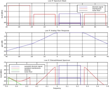
3.1 Receiver Channel Filtering and A/D Conversion In our channel filtering concept, receiver selectivity is shared between analog IF filtering and digital postfiltering follow-ing A/D conversion. The low-IF spectrum mask depicted in the upper part of Fig. 8 reflects the worst-case interfer-ence scenario (according to 802.11a) where the desired sig-nal (centered about 10 MHz) is surrounded by adjacent chan-nel interference (ACI) of some maximum level. The analog polyphase bandpass IF filter (center of Fig. 8) is designed so as to suppress only part of this interference (bottom of Fig. 8); its main purpose is to prevent aliasing and reduce the dynamic range of residual interference in subsequent A/D conversion. By virtue of this approach, analog filter com-plexity and power consumption is much reduced at the ex-pense of only one additional A/D converter bit and the need for a digital postfilter eliminating residual interference.
32 S. A. Fechtel: OFDM: From the Idea to Implementation
6
Figure 7. WLAN OFDM Baseband and RF PHY Transceiver Architecture
Figure 8. Low-IF Receiver Channel Filtering and A/D Conversion
-40 -30 -20 -10 0 10 20 30 40
-60 -50 -40 -30 -20 -10 0
Low IF Analog Filter Response
gain [dB]
-40 -30 -20 -10 0 10 20 30 40
-90 -80 -70 -60
Low IF Spectrum Mask
le
vel [dBm]
desired signal interference noise floor
-0.5 -0.4 -0.3 -0.2 -0.1 0 0.1 0.2 0.3 0.4 0.5 -100
-95 -90 -85 -80 -75 -70
Low IF Filtered/Aliased Spectrum
frequency
le
vel [dBm]
sampled desired signal sampled interference aliasing noise floor
IF TX 6...54 Mb/s
input
6...54 Mb/s output
PA low-IF upcon-version
LO from
MAC
scrambler convol. encoder interleaver QAM modulator
IFFT guard interval insertion
low-IF upconversion
TX IQ/DC compensation 20 MHz -> 80 MHz
center 0 -> 10 MHz
DAC DAC
low-IF signal
ADC ADC low-IF signal
low-IF filtering + downcon-version
preamble detection timing/frequency sync
guard
removal FFT
channel estimation subcarrier equalization
deinterleaver Viterbi decoder to
MAC IF
filter PGA PGA low-IF
downcon-version
LO LNA
80 MHz -> 20 MHz center 10 MHz -> 0
1
2
3
Fig. 8. Low-IF Receiver Channel Filtering and A/D Conversion.
Figure 9. A/D Conversion Level Budget
-21 dBV, 90 mVrms
-45 dBV, 5.6 mVrms
-23 dBV, 70 mVrms
-41 dBV, 8.9 mVrms
-54 dBV, 2.0 mVrms -10 dBV
-20 dBV
-30 dBV
-40 dBV
-50 dBV
-6 dBV, 500 mVp
PAR (crest factor, Vp/Vrms) -12 dBV, 250 mVp
rms_total
-4.4 dBV, 600 mVp DC-Offset (100mV)
rms_adjacent rms_desired 54 Mbps
6 Mbps
rms_noise
quantization
rms_quant
d
y
n
a
m
ic
r
a
n
g
e
~
6
*
W
e
ff
B
it
1.6 dB
AGC level variation 6 dB
9 dB
2 dB
18 dB
>9 dB 4 dB
A/D wordlength effective 8.6 bit physical 10 bit
S. A. Fechtel: OFDM: From the Idea to Implementation 33
8 Figure 10. Calibration Scheme for Transmitter I/Q and DC Compensation
Figure 11. Performance of Low-IF Transmitter I/Q Compensation
PA TX IQ / DC
compensation
TX calibration test generator
DAC DAC
ADC ADC
TX calibration measurement
(.)2 OFDM
TX
IF/RF TX
OFDM RX RF/IF
RX f 0 BB test signal
f0
f 0 fc-f0 fc fc+f0 RF TX DC testsignal
TX IQ
f 0 f0 BB
test signal TX
DC TX IQ
2*f0
Fig. 10. Calibration Scheme for Transmitter I/Q and DC Compensation.
8
Figure 10. Calibration Scheme for Transmitter I/Q and DC Compensation
Figure 11. Performance of Low-IF Transmitter I/Q Compensation
PA
TX IQ / DC
compensation
TX calibration
test generator
DAC
DAC
ADC
ADC
TX calibration
measurement
(.)
2
OFDM
TX
IF/RF
TX
OFDM
RX
RF/IF
RX
f
0
BB test
signal
f0
f
0 fc-f0 fc fc+f0
RF
TX DC testsignalTX IQ
f
0 f0
BB
test signal TX
DC TX IQ
2*f0
Fig. 11. Performance of Low-IF Transmitter I/Q Compensation.
for various RF/IF receiver imperfections such as DC off-set (1.6 dB) and gain control error (6 dB). As OFDM sig-nals exhibit a Gaussian-like probability density, their peak-to-average ratio (PAR, 9 dB or more) must be added. The rms level of the composite (desired + residual interference) signal is therefore much smaller than the A/D saturation level (90 mVrms). Depending on the data rate (6...54 Mb/s), the composite signal may comprise more or less amount of interference so that the desired signal level may be fur-ther depressed (here to 9...70 mVrms). The required SNR
34 S. A. Fechtel: OFDM: From the Idea to Implementation
9 Figure 12. FFT Architecture
Figure 13. FFT Wordlength Optimization and Quantization SNR
1 2 3 4 5 6 7 8 9 10 11
4 6 8 10 12 14
Wordlengths, Average/Maximum Signal Levels, Bittrue Range
bits
1 2 3 4 5 6 7 8 9 10 11
25 30 35 40 45 50 55
Average SNR
position index
dB
>> SR(2)
(2)
(output) (input)
>> SR(4) (twiddle W )
>>SA
>>ST
twiddle
>>SA Win
-WT
<<(WT-1-ST) Wout SA = 0 or 1
ST usually WT-1, may be WT-2 (WT-1-ST) usually 0, may be 1 SA and (WT-1-ST) not simultaneously 1
(1) stage 1
>> SR(3)
(3)
stage 2 stage 3
(4) >> SR(5)
(5) 8
>> SR(6) (twiddle W )
stage 4
(6) >> SR(7)
(7) 16
>> SR(8) (twiddle W )
stage 5
(8) >> SR(9)
(9) 32
>> SR(10) (twiddle W )
stage 6
(10) >> SR(11)
(11) 64
Fig. 12. FFT Architecture.
9 Figure 12. FFT Architecture
Figure 13. FFT Wordlength Optimization and Quantization SNR
1 2 3 4 5 6 7 8 9 10 11
4 6 8 10 12 14
Wordlengths, Average/Maximum Signal Levels, Bittrue Range
bits
1 2 3 4 5 6 7 8 9 10 11
25 30 35 40 45 50 55
Average SNR
position index
dB
>>
SR(2)
(2)
(output) (input)
>>
SR(4)
(twiddle W )
>>SA
>>ST
twiddle
>>SA
Win
-WT
<<(WT-1-ST) Wout SA = 0 or 1
ST usually WT-1, may be WT-2 (WT-1-ST) usually 0, may be 1 SA and (WT-1-ST) not simultaneously 1
(1) stage 1
>>
SR(3)
(3)
stage 2 stage 3
(4)
>> SR(5)
(5) 8
>>
SR(6)
(twiddle W ) stage 4
(6)
>>
SR(7)
(7) 16
>>
SR(8)
(twiddle W )
stage 5
(8)
>> SR(9)
(9) 32
>>
SR(10)
(twiddle W )
stage 6
(10)
>> SR(11)
(11) 64
Fig. 13. FFT Wordlength Optimization and Quantization SNR.
3.2 Radio Impairment Compensation: Transmitter I/Q Mismatch
The cost-sensitive mass market calls for direct conversion transceiver architectures. Unfortunately, direct conversion suffers from nonidealities such as DC offsets caused by lo-cal oscillator (LO) leakage or I/Q mismatch due to ampli-tude and/or phase imbalance between the two I (in-phase) and Q (quadrature-phase) rails carrying the complex-valued baseband signal. In the transmitter, such nonidealities lead to the emission of unwanted spurious signals which must be
suppressed in order to ensure standard compliance. To this end, the I/Q mismatch and DC calibration scheme shown in Fig. 10 has been implemented.
S. A. Fechtel: OFDM: From the Idea to Implementation 35
10 Figure 14. Performance of Implemented WLAN PHY Transceiver
5 10 15 20 25 30 35 40 45 50 55
0 5 10 15 20 25
Data Rate [Mbit/s]
Required SNR [dB]: A
WG
N (blue)
, E
TSI-A/C (red)
WLAN 802.11a OFDM RF+BB PHY Performance
Fig. 14. Performance of Implemented WLAN PHY Transceiver.
fc)of a complex sinusoidal test signal with (programmable) frequency +f0 therefore yields RF signal components at
fc+f0(desired),fc(DC offset), andfc−f0(unwanted spur from I/Q mismatch). Squaring the RF signal then yields (real-valued) signal components at f0 (DC) and 2f0 (I/Q) (left-hand side of Fig. 10) which can be observed by tuning the measurement unit to these frequencies. The IQ/DC com-pensator settings can now be adapted such that, after sev-eral measurement and control cycles, the unwanted signals are suppressed to the extent that their energy is below some predefined threshold. The optimal compensator settings thus found are stored and used during subsequent regular WLAN operation.
I/Q calibration performance thus achieved is illustrated by Fig. 11. The IQ/DC-compensated low-IF transmitter (cen-ter frequency 10 MHz upconverted to 5270 MHz) is seen to improve SSB suppression from 25...30 dB without compen-sation to more than 45 dB, thus complying with the 802.11a TX spectrum mask.
3.3 FFT Design
OFDM modulation and demodulation is most efficiently per-formed by IFFT and FFT processors, respectively. In our implementation, both IFFT and FFT units are based on the same radix-2 pipelined architecture shown in Fig. 12, how-ever with different wordlengths. The 64-point (I)FFT con-tains six stages, and each stage consists of a butterfly proces-sor element (upper part of Fig. 12) with two input and output ports of wordlengthWinandWout, respectively. Internal but-terfly operations comprise twiddle multiplication (complex
exponential with wordlength WT, complex multiplication, right shiftST), a left shift(WT−1−ST), two complex additions, and two right shiftsSAat the output. In the first two stages, twiddle multiplications simplify to additions.
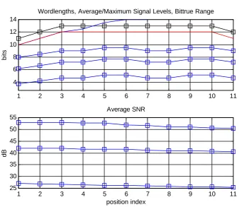
As the 64 input signal samples ripple through the six stages, they are subject to bit-true arithmetic operations which introduce some amount of quantization noise. So from one observation point to the next (1 to 11 in Fig. 12), the quantization noise level continually rises. Focusing on wordlength design for the OFDM demodulator, the art of FFT wordlength design consists in minimizing the wordlengths yet keeping the quantization noise below a cer-tain target level, or, equivalently, keeping the loss in quanti-zation SNR below some limit. As the received and filtered singal may vary in strength, this must hold for a range of input signal levels. In this design, the average FFT input bit-true signal level may deviate considerably from its target value 72 (∼6 bit, medium level) and range between about 12 (<4 bit, low AGC gain, strong ACI, 6 Mb/s mode) and 250 (∼8 bit, high AGC gain, no ACI, 54 Mb/s mode).
36 S. A. Fechtel: OFDM: From the Idea to Implementation
Table 2. WLAN Standard 802.11a/g: PHY Transmission Parameters.
2 Table 1. Basic Parameters of Wireless LAN Standards and Standard Proposals
Standard Band, Channel, Modulation maximum PHY rates 802.11b 2.4 GHz, 25 MHz channel, DSSS/CCK 11 Mb/s
802.11a/g 5/2.4 GHz, 20 MHz channel, OFDM 54 Mb/s 5/2.4 GHz, 20/40 MHz channel, OFDM
20 MHz (optional), 40 MHz (mandatory) 2x2 (mandatory) or 4x4 MIMO OFDM
140 / 315 Mb/s (2x2, 20/40 MHz) 280 / 630 Mb/s (4x4, 20/40 MHz) 802.11n
TGn Sync Proposal WWiSE Proposal
20 MHz (mandatory), 40 MHz (optional) 2x2 (mandatory) or 4x4 MIMO OFDM
135 / 270 Mb/s (2x2, 20/40 MHz) 270 / 540 Mb/s (4x4, 20/40 MHz) Gbit/s
WLAN
5/17/24/60 GHz bands, 100 MHz channel, up to 4x4 MIMO OFDM
more than 1 Gb/s
Table 2. WLAN Standard 802.11a/g: PHY Transmission Parameters information data rate 6, 9, 12, 18, 24, 36, 48, 54 Mbit/s channel bandwidth = sampling rate 20 MHz, occupied bandwidth 16.6 MHz OFDM symbol length 4.0 µs = 80 samples
useful symbol length = FFT length 3.2 µs = 64 samples guard interval length 0.8 µs = 16 samples number of occupied subcarriers 52
number of data subcarriers 48 number of pilot subcarriers 4
subcarrier frequency spacing 312.5 kHz (=20 MHz / 64) subcarrier modulation BPSK, QPSK,16-QAM, 64-QAM forward error correcting code convolutional code, K=7, rates 1/2, 2/3, 3/4
Figure 15. First-Generation WLAN PHY Transceiver Board
BB PHY IC
RF Transceiver
Power Amplifier
Power Supply
Diplexer
Switch
Fig. 15. First-Generation WLAN PHY Transceiver Board.
to 12 bit at its output, which compares favorably with the 6 extra bits (= number of stages) normally required. Also, the bit-true saturation level (= wordlength-1) is more than 2 bits above the maximum average signal level, thus grant-ing more than 12 dB peak-to-average ratio (PAR) headroom. From the lower drawing of Fig. 13, the loss in quantization SNR across positions 1 to 11 (again for weak, medium, and strong signal levels) is seen to remain small; the quantization noise introduced by the optimized FFT architecture is about 20 dB below the ambient noise level and therefore negligible at all relevant signal levels.
4 WLAN Transceiver Performance
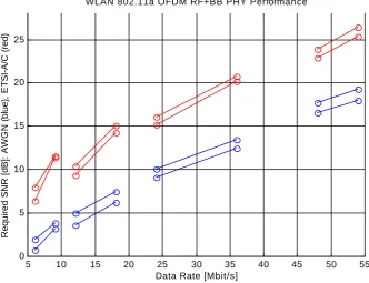
S. A. Fechtel: OFDM: From the Idea to Implementation 37 between 8 and 26 dB is required for these channels. The
ref-erence results for ideal floating-point transceiver processing also shown in Fig. 14 (dashed lines) reveal that the imple-mentation loss of the realized radio and baseband PHY de-vice is less than 2 dB, which compares very favorably with other solutions on the market. Figure 15 displays the cur-rent WLAN PHY transceiver board housing baseband and radio transceiver chips, power amplifier, and circuitry for an-tenna switching and power supply. Next-generation imple-mentation are targeting one-chip solutions for the radio and all PHY and MAC processing.
5 Conclusions
Despite the presence of multipath, OFDM modulation – fea-turing a set of smallband subcarriers and a guard interval – preserves orthogonality both in time and frequency and thus greatly facilitates channel equalization. Important aspects of OFDM radio and baseband transceiver implementation have been discussed. The concept of sharing receiver channel se-lection filtering between the analog and digital domains has a number of advantages but requires harmonizing the de-signs of analog filter, A/D converter, and subsequent digi-tal processing. Radio impairments such as transmitter DC and IQ mismatch are best compensated for by means of dig-ital predistortion with parameters determined by calibration. A methodology for optimizing the performance-complexity tradeoff in OFDM demodulation has been demonstrated on the pipelined FFT architecture and its wordlengths. These and other measures were shown to result in less than 2 dB implementation loss, which is a very competitive figure of merit for the entire radio and baseband transceiver.
Acknowledgements. The author would like to thank U.R.S.I. and
especially K.-J. Langenberg for the invitation to present this paper.
References
Bingham, J. A. C.: Multicarrier modulation for data transmission: an idea whose time has come, IEEE Commun. Mag., 37, 5–14, May 1990.
Coffey, S., Jones, V. K., Hamady, N., et al.: WWiSE IEEE 802.11n proposal, doc.: IEEE 802.11-04/0935r3, September 2004. ETSI EN 300 744: Digital Video Broadcasting (DVB); framing
structure, channel coding and modulation for digital terrestrial television, V1.4.1, January 2001.
ETSI DVB Document A081: Transmission system for handheld ter-minals (DVB-H), June 2004.
Fechtel, S. and Blaickner, A.: Efficient FFT and equalizer imple-mentation for OFDM receivers, IEEE Trans. Consumer Electron-ics, 45, November 1999.
Fechtel, S., Sch¨ollhorn, P., Speth, M., Fock, G., and Schotten, C.: Advanced receiver chip for terrestrial digital video broadcasting: architecture and performance, IEEE Trans. Consumer Electron-ics, 44, August 1998.
Foschini, G. J.: Layered space-time architecture for wireless com-munication in a fading environment when using multi-element antennas, Bell Labs Technical Journal, 1, No. 2, 41–59, Autumn 1996.
Foschini, G. J. and Gans, M. J.: On limits of wireless communi-cations in a fading environment when using multiple antennas, Wireless Personal Communications, 6, 311–335, 1998. Foschini, G. J., Golden, G. D., Valenzuela, R. A., and Wolnianski,
P. W.: Simplified processing for high spectral efficiency wireless communication employing multi-element arrays, IEEE Journal on Selected Areas of Communications, 17, No. 11, 1841–1852, November 1999.
IEEE 802.11a: Wireless LAN medium access control (MAC) and physical layer (PHY) specifications: high speed physical layer in the 5 GHz band, July 1999.
IEEE 802.11b: Standard for wireless LAN medium access control (MAC) and physical layer (PHY) specifications, 2001.
IEEE 802.11g: Wireless LAN medium access control (MAC) and physical layer (PHY) specifications further higher-speed phys-ical layer extension in the 2.4 GHz band, Supplement to IEEE Standard, 2003.
Jones, V. K., Raleigh, G., and van Nee, R.: MIMO answers high-rate WLAN call, EE Times, December 2003.
Kammeyer, K. D., Schmidt, H., R¨uckriem, R., and Fechtel, S.: OFDM: An old idea solves new problems, in: Proc. Int. Symp. Theoretical Electrical Engineering (ISTET), 2, Linz, Austria, August 2001.
Meyr, H., Moeneclaey, M., and Fechtel, S.: Digital communication receivers, Wiley Interscience, 1997.
Mujtaba, A., Stephens, A. P., Purkovic, A., et al.: TGn Sync com-plete proposal, IEEE presentation, September 2004.
Pawlowski, S.: Motivation for a reconfigurable wireless architec-ture, Intel Labs, January 2003.
Pirsch, P.: Architectures for digital signal processing, Wiley Inter-science, 1998.
Speth, M., Fechtel, S., Fock, G., and Meyr, H.: Optimum receiver design for wireless broadband systems using OFDM – Part I, IEEE Trans. Commun., 47, November 1999.
Speth, M., Fechtel, S., Fock, G., and Meyr, H.: Optimum receiver design for OFDM-based broadband transmission – Part II: A case study, IEEE Trans. Commun., 49, April 2001.
Vermeer, V. and Cramer, M.: Wireless eyes throughput challenge, EE Times, December 2003.
Wireless Gigabit with advanced multimedia support (WIGWAM), Project Proposal, June 2003.