Please cite this article as: F. Ahmed, Y. Feng, R. Li,A Multiband Multiple-input Multiple-output Antenna System for Long Term Evolution and Wireless Local Area Networks Handsets, International Journal of Engineering (IJE), TRANSACTIONS B: Applications Vol. 29, No. 8, (August 2016) 1087-1093
International Journal of Engineering
J o u r n a l H o m e p a g e : w w w . i j e . i rA Multiband Multiple-input Multiple-output Antenna System for Long Term
Evolution and Wireless Local Area Networks Handsets
F. Ahmed*a, Y. Fengb, R. Lic
a Department of Information and Communication Engineering, University of Rajshahi, Rajshahi, Bangladesh b School of Automation Science and Engineering, South China University of Technology, Guangzhou, China c School of Electronic and Information Engineering, South China University of Technology, Guangzhou, China
P A P E R I N F O
Paper history: Received 03 May 2016
Received in revised form 21 June 2016 Accepted 14 July 2016
Keywords:
Long Term Evolution (LTE) wireless local area networks (WLAN) Multiple-input multiple-output (MIMO) Multiband
Compact Handset Antenna
A B S T R A C T
A novel multiband multiple-input-multiple-output (MIMO) antenna system is proposed. The MIMO antenna system consists of two antenna elements, each of which comprises of three radiators: a driven monopole, an S-shaped strip and an inverted F-shaped strip and occupies footprint of 15x18.5x0.8 mm3 only. The driven monopole acts as a quarter-wave monopole and stimulates higher mode resonance. The two strips are excited by electromagnetic coupling from the driven monopole and serve as two additional monopoles leading to a wideband performance for the lower band. The bandwidths (VSWR ≤ 2.75) achieved for the antenna element are 1.67 – 2.2 GHz for the lower band and 2.28 –2.95 GHz for the upper band which cover LTE-1, LTE- 2, LTE- 3, LTE- 7, LTE- 40 and WLAN 2.4 GHz bands. A T-shaped slot and another two slots are introduced to reduce the coupling effect between the two multiband antenna elements. The isolation achieved is higher than 18 dB over the whole band, leading to an envelope correlation coefficient of less than 0.01. Furthermore, the diversity characteristics of mean effective gains (MEGs) and diversity gain (DG) are also studied. Both the simulated and measured results are shown to illustrate the performance of the proposed multiband MIMO antenna system, and that confirms the suitability for Long Term Evolution (LTE) and wireless local area network (WLAN) handset applications.
doi: 10.5829/idosi.ije.2016.29.08b.08
1. INTRODUCTION1
Future mobile communication system requires higher data rate supportable handsets to enable on-demand services e.g. internet accessing, video conferencing, online-gaming and so on. But the channel capacity of a conventional single-input single-output (SISO) communication system is limited in terms of the Shannon’s law [1]. MIMO technologies play a vital role in the emerging wireless communications, such as LTE [2] and WLANs [3]. MIMO antenna techniques improve system performance in terms of coverage, spectral efficiency and high data rate without additional power requirements [4, 5] which has been increased demand for integrating multiple antenna elements in a
1*Corresponding Author’s Email:[email protected] (F. Ahmed)
mobile handset. However, compact multiband MIMO antenna design for mobile handset is more challenging in many aspects unlike other applications due to its limited space, compactness and thinness.
range of 1700-2900 MHz. The total size of the system is about of 55×99×1.6 mm3 and isolation is better than 15 dB. Though the antenna has overall better performance but the structure is not fit for further 3/4-element antenna array systems into the limited volume of mobile handset without compromising system’s size.
In this paper a planar compact multiband MIMO antenna has been developed for LTE-1 (1920-2170 MHz), LTE-2 (1850-1990 MHz), LTE-3 (1710-1880 MHz), LTE-7 (2500-2690 MHz), LTE-40 (2300-2400 MHz), and WLAN 2.4 GHz (2400-2484 MHz) applications. A compact multiband antenna element is proposed first, and then a two-element MIMO antenna system is developed.
2. A MULTIBAND ANTENNA ELEMENT DESIGN
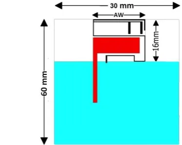
The configuration of a single element multiband antenna proposed for the MIMO antenna system is illustrated in Figure 1. The single antenna element consists of a driven monopole (orange colored), an S-shaped strip (blue colored) and an inverted F-S-shaped strip (red colored). The S-strip is short circuited to the ground plane through Via (H). The driven monopole is connected to a 50- Ω microstrip feed line, while both
the S-shaped and F-shaped strips are
electromagnetically (EM) coupled to the driven monopole. The electromagnetic coupling helps in the bandwidth enhancement for the lower band. The driven monopole acts as a quarter-wave monopole and stimulates higher mode resonance. The two strips are excited by electromagnetic coupling from the driven monopole and serve as two additional monopoles leading to two additional resonance modes for the lower band.
However, the details are studied and discussed in subsection 3.2. A combination of the two resonances with the higher-order mode excited on driven monopole leads to a wideband performance. The bandwidth (reflection coefficient >-6 dB) achieved for the antenna element is 1.69 – 2.71 GHz covering LTE-1, LTE-2, LTE-3, LTE-7, LTE-40 and WLAN 2.4 GHz bands shown in Figure 2. The multiband antenna element was analyzed using Ansoft HFSS and all the optimized geometric parameters’ values are listed in Table 1. The proposed antenna element occupies a footprint of 16×18.5mm2 and the total system size is 60×30×0.8mm3 only which is a very good candidate for the MIMO antenna system.
3. A MULTIBAND MIMO ANTENNA SYSTEM
3. 1 MIMO Antenna Design The single antenna element, designed and discussed in section 2, is
employed to develop a two-element multiband MIMO antenna system shown in Figure 3.
Figure 1. Geometry of the proposed multiband antenna element
TABLE 1. Optimized parametric values (Unit: Millimeter)
Factors Values Factors Values Factors Values
SH 110 G3 1.75 H7 2.25
SW 60 G4 0.5 H8 2.75
AH 15 G5 0.75 L1 18.5
MH 8.5 G6 3.05 L2 12.25
ML 16.5 H1 4 L3 3.5
MW 5.5 H2 0.8 L4 18.5
FL 17.5 H3 5.2 L5 4
FW 1.45 H4 4.15 L6 10.25
G1 0.6 H5 4.4 W1 0.5
G2 0.4 H6 9.25 W2 0.25
W3 0.75 W4 0.4 HTL 11
HTW 1 VTH 30 VTW 1
VSH 16 VSW 1.5 HSH 1
HSW 28 AW 18.5
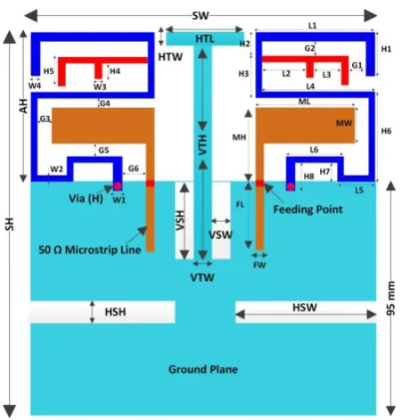
Figure 3. Geometry and dimensions of the proposed multiband two-element MIMO antenna system with decoupling slots
The two identical antenna elements have the same structure and dimensions as listed in Table 1. In contrast to, simply an extended size of the substrate (110×60 mm2) and ground plane (95×60 mm2) has been introduced. Each antenna element is printed on the top of the front side of a low cost FR-4 substrate and separated from each other by 23mm, approximately 0.13λ0 (where, λ0=176mm is the free space wavelength)
at the lowest frequency (1.71GHz) of the operating band. A 17.5×1.45mm2 50- Ω microstrip fed-line is also printed on the front side of the substrate. On the back side of the substrate a system ground plane of size 95×60 mm2 is printed. However, after a fine tuning and optimization, each antenna element occupies a footprint of 15×18.5mm2 only which makes the antenna element fit for MIMO configuration within a compact volume for mobile handsets. The details operating principles of MIMO antenna system are studied and discussed in subsection 3.2. Due to minimizing mutual coupling effects and hence, to improve isolation, a protruded T-shaped metal strip with rectangular cutting slots, and two symmetric ground slots have been introduced and details working steps are explained in subsection 3.3. However, the optimized layout of the proposed multiband MIMO antenna, with decoupling features and its dimensional details, is illustrated in Figure 3.
A prototype of the two-element MIMO antenna is viewed in Figure 4. The antenna was fabricated on a FR-4 substrate (εr=4.6, thickness = 0.8mm, loss tangent,
δ = 0.02) of dimension 110x60mm2
. The measured voltage standing wave ratio (VSWR) of the proposed
MIMO antenna is compared with simulation results shown in Figure 5 and a good agreement is observed. The achieved bandwidths (VSWR ≤ 2.75) are around 27.4% (1.67-2.2 MHz) and 25.6% (2.28-2.95 GHz).
3. 2. Operating Principle and Parameter Study The fundamental operating principles are analyzed with the aid of simulated reflection coefficient shown in Figure 6. The corresponding dimension of Ref. 1, Ref. 2, and Ref. 3 are fixed and the same as the optimized values listed in Table 1. In case of driven monopole only (Ref. 1), a wide resonant mode is observed at around 2.8 GHz. The length of the driven monopole is about 25mm up to feed point (A) that can excite a quarter-wavelength (λ/4) resonant mode. After adding S-shaped strip (Ref. 2), a second resonant mode at around 2.16 GHz is generated and in the meantime, the first resonant mode is shifted to about 2.56 GHz with improved impedance matching. In fact, the length of the S-shaped strip is around 75mm that can excite a half-wavelength (λ/2) resonant mode.
Figure 4. Prototyope of the proposed two-element MIMO antenna system
Further, by adding an F-shaped coupled strip (Ref. 3), a 3rd resonant mode is formed at around 1.83 MHz and the impedance of the 2nd resonant mode is improved. The length of F-shaped strip itself is about 20mm, but with the partial S-shaped strip the total length is about 67 mm that generates a half-wavelength (λ/2) resonant mode at 1.83 GHz. The reason behind of exciting (λ/2) resonant mode is that both the S- and F-shaped strips are electromagnetically coupled with the driven monopole. Unlike direct feeding, couple-fed generally decreases the input impedance and hence lengthens the electrical length of the radiator [10]. Moreover, F-shaped strip is also capacitively coupled with the S-shaped strip and hence the inductive reactance is compensated by the coupling capacitance introduced by the small gap between the S-shaped and F-shaped strip which extends the length of F-strip electrically [8] and hence excites the 3rd resonant mode. However, while all of the radiators are properly tuned and integrated together, a wide operating band of frequencies is achieved as shown in Figure 5.
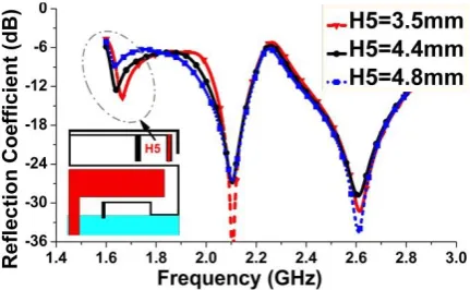
Figure 7 shows the simulated reflection coefficient with varying length of H1 while other values are fixed as listed in Table 1.
Figure 6. Reflection coefficient (dB), in case of (i) Driven Monopole only (Ref. 1), (ii) S-shaped Strip with Monopole (Ref. 2), and (iii) F-shaped Strip with S-strip & Monopole (Ref. 3)
Figure 7. Effect of the length (H1) of S-Shaped strip on the reflection coefficient of the proposed MIMO antenna, where H1= 4mm is an optimized value
As H1 (hence the length of S-shaped strip) is decreased, the 2nd resonant frequency is shifted towards the higher frequency or vice-versa without having any effect on other two resonant modes. In Figure 8, it is evident that the 3rd resonant frequency is shifted towards the higher frequency as H5 (hence the length of F-shaped strip) is decreased or vice-versa with having minor effect on other two resonant modes. Therefore, it is inferred that radiation characteristic within the 2nd and 3rd resonant modes over the operating bands are controlled and contributed by the S-shaped and F-shaped strip respectively.
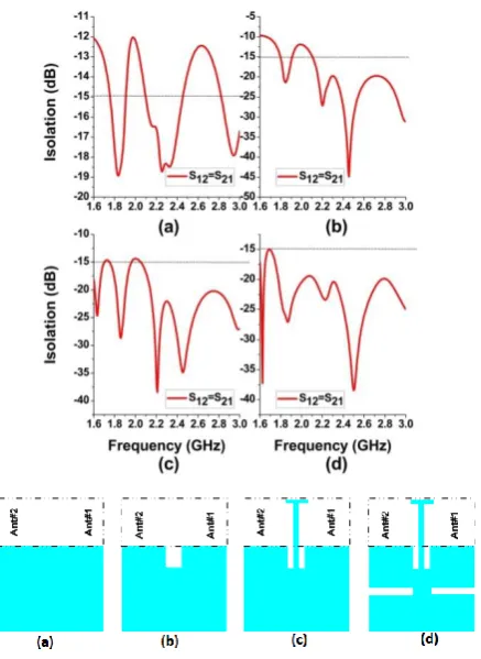
3. 3. Decoupling Techniques Analysis As a decoupling technique, two symmetric rectangular slots and a protruded T-shaped strip with rectangular slots have been studied into the ground plane. In principle, its function is to provide anti-phase coupling currents to eliminate the original coupling currents. Whereas the cutting slots reduce the mutual coupling effects caused by distributed ground surface currents. The ground slots act as a band stop filter and also make slow the surface currents flow over the finite ground plane. However, to explain how the imprinted ground slots and protruded T-shaped ground strip reduce the mutual coupling, the average surface current distribution (considering that antenna element 1 at the right side is excited while the left antenna element 2 is terminated by 50- Ω load) at center frequency of 2GHz is studied and shown in Figure 9(a)-(b). It is observed that a large portion of surface currents has been trapped by the applied slots as shown in Figure 9(b). Furthermore, to evaluate the effectiveness of the applied decoupling techniques, the step-by-step isolation procedures are illustrated in Figure 10(a)-(b). Finally, the measured isolation curves for the proposed MIMO antenna are compared with the simulation results and plotted in Figure 11. It is observed that the isolation is greater than 18 dB over the operating bands.
Figure 9. Surface current distribution of two-element MIMO antenna at 2GHz (a) Without decoupling techniques and (b) With decoupling techniques
Figure 10. Simulated Isolation Curves for the case of (a) Conventional rectangular ground plane, (b) Vertical slot eatched into the ground plane, (c) Protruded T-shaped strip with vertical slot and (d) Proposed modified ground plane
Figure 11. Isolation comparison of the proposed MIMO antenna
4. ANTENNA PERFORMANCE EVALUATION
4. 1. Envelope Correlation Coefficient (ρe) In
the case of isotropic/uniform signal propagation environment, the envelope correlation coefficient (ρij)
can be computed by Equation (1) [11],
2
2 2
2 2
* *
1
1 ii ji jj ij
jj ij ij ii es
ij
S S
S S
S S S S
(1)
The simulated and computed envelope correlation coefficients obtained from measured S-parameter values are plotted in Figure 12. It is observed that in any of two
antenna elements combinations the measured
correlation coefficient, ρe of the proposed MIMO
antenna are always below 0.01, which leads to a perfect performance in terms of diversity.
4. 2. Mean Effective Gain and Diversity Gain In the case of mobile wireless environment for a series of assumptions [12], the mean effective gains (MEGs) can be calculated by Equation (2). The MEGs obtained from measured radiation data are listed in Table 2. It is found that the MEG for each antenna element is almost identical. In worst case situation, the maximum ratio of the MEG between any of the two antenna units is not more than 1.7 dB. Therefore, the received signals satisfy the conditions Pi≈Pj (|MEGi/MEGj| < 3 dB) [13].
d
G G MEG
i i i
2
0 ,
2 1
, 2 1
2
1 (2)
where Gθi(Ω) and Gφi(Ω) are the power gain patterns
of ith antenna, and Γ represents the cross polarization discrimination; assuming Γ= 0 dB in indoor fading environment [13].
TABLE 2. Mean Effective Gain (MEGs) and Diversity Gain (DG) for the prototype
Center Frequency
(GHz)
Mean Effective Gain in dB (Indoor, Γ = 0 dB) K
(dB)
DG, 1% (dB) Ant. #1 Ant. #2
1.80 -17.50 -17.46 0.04 9.95
1.92 -22.49 24.18 1.69 8.30
2.10 -09.83 -08.52 1.31 8.68
2.35 -08.78 -08.33 0.44 9.56
2.45 -09.42 -08.73 0.69 9.31
2.60 -11.54 -10.73 0.81 9.19
Under the selected combining scheme and at 99% link reliability, the computed diversity gain (DG) by using Equation (3) and Equation (4) [14], which are obtained from the measured data, are presented in Table 2. The high diversity gains are obtained over the operating bands.
KDG
DG e
ij .
1 .
0
(3)
1 2 2 1
, min
MEG MEG MEG MEG
K (4)
where, DG010dB [14] represents the ideal diversity gain of the antenna.
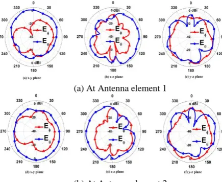
4. 3. Radiation Characteristics The measured 2D radiation patterns of the proposed MIMO antenna at 2.5 GHz frequency are plotted in Figure 13. It is observed that the radiation pattern is almost omnidirectional and tends to cover the complementary space region. This approach can overcome the multipath fading problems and enhance the systems performance.
(a) At Antenna element 1
(b) At Antenna element 2
Figure 13. Measured 2D radiation patterns at 2.5 GHz
5. CONCLUSION
A printed two-element multiband MIMO antenna system is developed for LTE-1, LTE-2, LTE-3, LTE-4, LTE-7, LTE-40, and WLAN 2.4GHz communication handsets. The measured bandwidths (VSWR ≤ 2.75) are around 530 MHz and 670 MHz, respectively. The applied decoupling techniques work effectively and hence high isolation (> 18 dB) is achieved. The MEGs, DGs and correlation coefficients are computed from the measured far-field radiation patterns and ensuring high diversity performance. The proposed MIMO antenna occupies total size of 110×60×0.8mm3, which is a typical mobile handset’s size for practical usage and
even comparable with the total size
(123.8×58.6×7.6mm3) of the latest IPhoneSE21 mobile handset. Moreover, a footprint of each single antenna element is 16×18.5mm2 only, which may make it fit for more than two-element antenna array system as well.
6. REFERENCE
1. Shannon, C.E., "A mathematical theory of communication", ACM SIGMOBILE Mobile Computing and Communications Review, Vol. 5, No. 1, (2001), 3-55.
2. Li, Q., Li, G., Lee, W., Lee, M.-i., Mazzarese, D., Clerckx, B. and Li, Z., "Mimo techniques in wimax and lte: A feature overview", IEEE Communications Magazine, Vol. 48, No. 5, (2010), 86-92.
3. Paul, T. and Ogunfrunmiri, T., "Wireless lan comes of age: Understanding the ieee 802.11 n amendment", IEEE Circuits and Systems Magazine, Vol. 8, No. 1, (2008), 28-54.
4. Dahlman, E., Parkvall, S., Skold, J. and Beming, P., "3g evolution: Hspa and lte for mobile broadband, Academic press, (2010).
5. Foschini, G.J. and Gans, M.J., "On limits of wireless communications in a fading environment when using multiple antennas", Wireless Personal Communications, Vol. 6, No. 3, (1998), 311-335.
6. See, C.H., Abd-Alhameed, R.A., Abidin, Z.Z., McEwan, N.J. and Excell, P.S., "Wideband printed mimo/diversity monopole antenna for wifi/wimax applications", IEEE Transactions on Antennas and Propagation, Vol. 60, No. 4, (2012), 2028-2035.
7. Hsu, C.-C., Lin, K.-H. and Su, H.-L., "Implementation of broadband isolator using metamaterial-inspired resonators and a t-shaped branch for mimo antennas", IEEE Transactions on Antennas and Propagation, Vol. 59, No. 10, (2011), 3936-3939.
8. Li, J.-F., Chu, Q.-X. and Huang, T.-G., "A compact wideband mimo antenna with two novel bent slits", IEEE Transactions on Antennas and Propagation, Vol. 60, No. 2, (2012), 482-489. 9. Shen, D., Guo, T., Kuang, F., Zhang, X. and Wu, K., "A novel
wideband printed diversity antenna for mobile handsets", in Vehicular Technology Conference (VTC Spring), IEEE., (2012), 1-5.
10. Chang, C.-H. and Wong, K.-L., "Printed-pifa for penta-band wwan operation in the mobile phone", IEEE Transactions on Antennas and Propagation, Vol. 57, No. 5, (2009), 1373-1381.
21
11. Hallbjorner, P., "The significance of radiation efficiencies when using s-parameters to calculate the received signal correlation from two antennas", IEEE Antennas and Wireless Propagation Letters, Vol. 4, No., (2005), 97-99.
12. Ko, S.C. and Murch, R.D., "Compact integrated diversity antenna for wireless communications", IEEE Transactions on Antennas and Propagation, Vol. 49, No. 6, (2001), 954-960.
13. Vaughan, R.G. and Andersen, J.B., "Antenna diversity in mobile communications", IEEE Transactions on Vehicular Technology, Vol. 36, No. 4, (1987), 149-172.
14. Gao, Y., Chen, X., Ying, Z. and Parini, C., "Design and performance investigation of a dual-element pifa array at 2.5 ghz for mimo terminal", IEEE Transactions on Antennas and Propagation, Vol. 55, No. 12, (2007), 3433-3441.
A Multiband Multiple-input Multiple-output Antenna System for Long Term
Evolution and Wireless Local Area Networks Handsets
F. Ahmeda, Y. Fengb, R. Lic
a Department of Information and Communication Engineering, University of Rajshahi, Rajshahi, Bangladesh b School of Automation Science and Engineering, South China University of Technology, Guangzhou, China c School of Electronic and Information Engineering, South China University of Technology, Guangzhou, China
P A P E R I N F O
Paper history: Received 03 May 2016
Received in revised form 21 June 2016 Accepted 14 July 2016
Keywords:
Long Term Evolution (LTE) wireless local area networks (WLAN) Multiple-input multiple-output (MIMO) Multiband
Compact Handset Antenna
هديكچ
یدٍرٍ ذٌچ يیًَ يتًآ ًِاهاس کی
-یجٍرخ ذٌچ
(MIMO)
ءسج ٍد زا ُذض دای يتًآ ًِاهاس.تسا ُذض ِئارا ُذًاب ذٌچ
:تسا ُذٌٌک صبات ِس لهاض کیرّ ِک تسا ِتفای ليکطت يتًآ راًَ کی ،کیرحت یبطق کت کی
S
راًَ کی ٍ لکض
F
لکض
ٍ سَکعه اٌْت یاپاج کی
mm3
11 * 1..1 * 0.. . ذه ٍ ذٌک یه لوع جَه عبر یبطق کت کی ترَص ِب کیرحت یبطق کت
یذیذطت راًَ ٍد .ذٌک یه یزاس ِيبض ار رتلااب ىاٌَع ِب ٍ ذًَض یه کیرحت یبطق کت زا یسيطاٌغهٍرتکلا جیٍست اب رگید
.ذٌٌک یه لوع ذًاب ييیاپ رد ،ذًاب يْپ راتفر یارب یفاضا یبطق کت ٍد ُذهآ تسذب یاّذًاب یاٌْپ
(VSWR<2.75)
یارب
زا ذًا ترابع يتًآ
GHz
2 / 2 -76 / 1 ٍ ذًاب ييیاپ رد
GHz
51 / 2 -2. / 2 یاّ ذًاب ِکذًاب یلااب رد
LTE-1, LTE-2,
LTE-3, LTE-7,LTE-40
ٍ
WLAN 2.4GHz
.ذًاضَپ یه ار فاکض کی
T
صّاک یارب رگید فاکض ٍد ٍ لکض
زا صيب ذًاب ماوت یٍر ُذهآ تسذب یزاساذج .تسا ُذض ِيبعت ُذًابذٌچ يتًآ رصٌعٍد جیٍست رثا
dB
1. ِب رجٌه ِک تسا
یگتسبوّ بیرض شَپ زا رتوک
01 / 0 .تسا ُذض يیا رب ٍُلاع
رثَه ُرْب ييگًايه یاّ ِصخطه
(MEGs)
ُرْب ٍ
یتيسرَیاد
(DG)
.تسا ُذض یسررب سيً ذٌچ يتًآ راتفرات تسا ُذض ُداد ىاطً یريگ ُزاذًا ٍ یزاس ِيبض ِجيتً ٍد رّ
ُذًاب
MIMO
تذه زارد لَحت یارب ىدَب بساٌهٍ ذطکب ریَصت ِبار
(LTE)
یاّ ِکبض رد ُاروّ یضَگ یاّ دربراک ٍ
یلحه نيسيب
(WLAN)
.ذٌک یه ذيیات ار