Global Journal of Advanced Engineering Technologies and Sciences
ANALYSIS OF SINGLE POINT CUTTING TOOLS WITH DIFFERENT
TOOL MATERIALS AND JOB MATERIALS
Deepesh Gehlot
1, Anil Elisala
21Assistant Professor, 2Research Scholar
1, 2 BM College of Engineering and Technology, Indore (M.P.) INDIA
ABSTRACT
Cutting technologies are the engines behind manufacturing. Without cutting, none of modern product would ever been place into service. Developing new materials directly wants analysis for method windows in cutting. Vast engineering efforts brought cutting within the position where it's these days and despite all rumors attempting to declare, that cutting is superannuated or cutting analysis is finished it's still a significant field of analysis and prone to fast innovations. Considering these facts present research work is devoted to investigations in cutting tools. For this purpose a single point cutting tool was targeted and investigations were made on Vonmises stresses and total deformations considering different types of tool materials and job materials. The tool materials were molybdenum high speed steel (Mb HSS) and Cubic Boron Nitride (CBN). The job materials were aluminium and tool steel. During the analysis, variation of parameters were analyzed by analyzing cutting forces, and varying depths of cut to 0.5 mm, 1 mm, 1.5 mm and 2 mm, and rack angles to 0º, 2º, 4º, 6º, and 8º. The results show that during the machining, cutting forces contribute greatest as compared to thrust and feed forces, and increase with depth of cut. Results of Vonmises stress analysis shows these stresses increase with increase in rack angle and depths of cut, irrespective of type of job material and tool material. At 1.5 mm and 2 mm depths of cut, von-misses stresses show same intensity, but value of deformations changes which depends on the type of materials used for tooling and job.
Keywords:
Single point cutting tool, CBN, HSS, rack angle.INTRODUCTION
The life of a tool is important in metal cutting since considerable time is lost whenever a tool is replaced or reset. Cutting tools lose its sharpness as usage continues and their effectiveness decrease over time. At some point during the life-span of the tool, it is necessary to replace, index or re-sharpen and reset the tool. Tool life is a measure of the length of time a tool will cut effectively. The life of cutting tool depends upon many factors, such as the microstructure of the material being cut, metal removal rate, the rigidity of the setup and effects of cutting fluid. Of all the factors the cost of cutting tool is very high. Tools of H.S.S, carbide, diamond tip cost very high. Therefore it is necessary to pay attention to increase the tool life. As the tool life increases, the variable cost decreases. In exact mechanism of metal cutting briefly stated is that a cutting tool exerts a compressive force on the work piece. Under this compressive force the material of the work piece is stressed beyond its yield point causing the material to deform plastically and shear off. The sheared material begins to flow along the cutting tool face in the form of small pieces called chips.
Considering above mentioned facts present research is devoted to the investigations in cutting tools. In present research work single point cutting tools are targeted. The materials for tools are Mb HSS and CBN (cubic boron nitride), and the materials for jobs are aluminium and tool steel. During the research work, analysis of different forces as well as effects of depths of cut and rack angles on von-misses stresses and deformation during turning operations are analyzed. For the purpose of analysis, a simulation approach is targeted, and the software used for analysis is ANSYS 14.0.
Following are the objectives of present research work.
1) Analysis of different forces acting on cutting tools during turning of hard and soft materials;
2) Analysis of effect of changes in rack angles during turning operations; and
3) Analysis of the effect of depths of cut on forces generated during turning operations considering different tool
as well as job materials
LITERATURE REVIEW
Present section tells about the details of research contributions of different researchers in the field of cutting tools, and concludes with identified gaps in research, the details of which are presented in upcoming sections.
Research Contributions in the Field of Cutting Tools
Details of research contributions made by different researchers in the field of cutting tools are as follows.
Table 1: Research Contributions in the Field of Cutting Tools
S.No Researchers (Year) Contribution
1. Orlowski et al. (2017) The cutting force is an energetic impact of cacophonic material, and can be thought-about from a point of view of contemporary fracture mechanics. Forecasting of the shear angle in cutting broaden potentialities for modeling of the cutting process even for skinny uncut chips. Such mathematical model has been developed here for description of the orthotropic materials’ cutting on the bottom of fracture theory, and includes work of separation (fracture toughness) in addition to the material plasticity and friction. the initial methodology of simultaneous determination of the fracture toughness and therefore the shear yield strength on the premise of wood cutting forces (or cutting power) is additionally conferred in this paper. The set of information necessary for computation is simply obtained whereas cutting wood with common rotating tools, such as a circular saw or a router bit. The results generated embody each fracture toughness and shear yield stresses in the shear plane, separately for two anatomical directions of wood. The simplicity and reliability of this methodology provides wide range of practical applications.
2. Liu et al. (2017) Orthogonal cutting may be a simplified two-dimensional model that neglects several geometric complexities, that describes complicated three-dimensional cutting method quite well in most cases. The orthogonal cutting ought to satisfy the plane strain assumption to stop the in depth deformation perpendicularly to the cutting direction owing to the pressure between the cutting tool and also the work piece, that is named as the side flow. To satisfy this assumption, the depth of cut (the uncut chip width) needs to be much larger than the feed (the uncut chip thickness) with a definite ratio. However, this criterion is not valid all the time. This paper presents an experimental study of the side flow with completely different cutting conditions by comparing the profiles of the cross section of the machined chip in machining of aluminum alloy. it is shown that the upper ratio between the uncut chip width and the uncut chip thickness (chip width-to-thickness ratio) and also the lower cutting speed will forestall the side flow during chip formation. A new criterion for plane strain assumption has been planned during this study as well.
3. Garcia-Gonzalez et al.
(2016)
near infrared radiation emitted by the rear face of the TiN coating to be imaged. A novel methodology is employed to measure the emissivity of the TiN/YAG interface. Using this technique, and the available blackbody calibration of the temperature vs. intensity response of the imaging system, the images are converted into temperature maps. The performance of the coated tool is additionally evaluated in terms of machining force and tool wear characteristics. Coatings that remain intact during the experiments can reduce ambiguity in interpretation of the results.
4. Lu et al. (2016) Cutting tools are direct performers in material cutting processes of nc machining, whereas the degree of cutter attrition and breakage directly influences the standard of production. Mean while tool condition recognition may be a key technique in automatic and unmanned machining process. Aimed toward this downside, the popularity of tool-condition based on machining feature in real-time is expressed. Machining options are used to build relationships between geometry, processing technology and monitoring signals so as to provide the premise for cutter condition identification. Feature info is established with experimental results and a cutter condition recognition system is established primarily based on this information. Experimental results recommended that the planned technique solves the problem of tool condition monitoring, particularly for production with multi varieties and small-batches.
5. Koleva et al. (2015) In the paper the chances of activity the dimensions of parts using the cutting tool that had machined the surfaces of the part are investigated. Described are the principal theme of the measuring device and its application for dimensional measurements. The method leads to additional efficient machining on CNC lathes. the applying of the tactic leads to automatic dimensional control, which otherwise would need specialized activity instrumentation or would result in increased idle time of the machine tool, automatic dynamic setup of the cutting tool, and automatic tolerance assurance using check-up data point surfaces. Reportable are the theoretical analysis of the measurement errors and also the methodology of predicting the accuracy of the measurements using the cutting tool itself. The results presented are experimental results of applying the system for direct dimensional measurements using the cutting tool on CNC lathe.
Gaps in the Research
On the basis of survey of available literature, following research gaps are being identified.
1) There is almost nil research available which shows the analysis of different forces generated during turning of
soft as well as hard materials;
2) There is almost nil research present which shows the comparison of different materials of cutting tools for machining soft and hard materials;
3) There is almost nil research available which shows the effect of changes in rack angle and depth of cut on the
performance of cutting tools.
Based on the gaps identified, objectives of the research work are being investigated.
SOLUTION METHODOLOGY
Forces during Turning: Mathematical Expressions
According to Shambharkar et al. (2016), in any metal cutting operation in a lathe there acts a force R on the tool.
This force R can be resolved into three components.
1.
Fx; a force in horizontal plane, parallel to the direction of the feed (thrust force);2.
Fy ; a force in horizontal plane perpendicular to the direction of feed (feed force); and3.
Fz; a force in vertical plane, perpendicular to both Fy and Fx (cutting force).Empirical formula determining the Fz can be expressed as under:
𝐹𝑍= 𝐶𝑃× 𝑡𝑋× 𝑆𝑌× 𝐾 (3.1)
…where,
Cp = coefficient, characterized by the work material and condition of working such as tool, coolant;
t = depth of cut;
S = feed in mm/revolution;
K = overall correlation, consisting of actual condition of working and tool angles, which varies from 0.9 to 1.0. The components approximately connected by the following expression
Fx / Fz = 0.3 (3.2)
…and
Fy /Fz = 0.2 (3.3)
Software used for Simulation
In the present research work, the software used for simulation is ANSYS, the details of which are presented as follows.
ANSYS is considered as one of the renounced tools in the field of simulation, developed by ANSYS Inc., USA. It can be used successfully for the purpose of simulating problems of thermal analysis, structural analysis, computational fluid dynamics, harmonic analysis, modal analysis, transient dynamics, buckling, and other categories. In addition to this, software also offers the facility to develop simple models. With the help of inbuilt library, one can find out the properties of materials, and even add the desired properties or new materials with the known values of properties. ANSYS also include a set of models to solve complex problems of engineering, architecture, physical sciences, mathematical models and other applications. Following are the salient features of the software:
Offers excellent simulation facility;
Easy modules for different types of complex analysis like modal, transient, etc;
Offers different theoretical perspective to solve a problem with different inbuilt models;
Simple parts can be easily created;
Inbuilt library to offer material properties; and
Better graphics facilities.
In present research work software version ANSYS 14.0 is being used for analysis purposes.
CASE STUDY
Present section is devoted to application of research tools on the case problem, the details of which are presented as follows.
Implementation of Research Tools to the Case Problem
Following are the details of stepwise procedure used to solve the research problem.
1. First of all values of different forces acting on the cutting tool during turning were investigated with the help of
mm/revolution. The analysis was done for x = 1 mm and y = 0.5 mm. The depths of cut adopted were 0.5 mm, 1 mm, 1.5 mm, and 2 mm respectively. Values of Cp in equation 3.1 are taken as 225 for Mb HSS and 252 for CBN.
2. In next step, effect of variations of rack angles, depths of cut and tool as well as job materials was investigated.
For this purpose, first of all a standard single point cutting tool was designed using modeling software with the following tool signature.
a) Total length = 12 cms
b) Tip formation = 4.5 cms
c) Back rake angle = 0°
d) Side rake angle = 7°
e) End relief angle = 6°
f) Side relief angle = 8°
g) End cutting edge angle = 15°
h) Side cutting edge angle = 16°, and
i) Nose radius = 0.8 mm
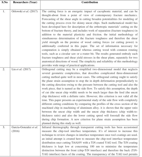
3. In next step, geometry was imported in simulation software (ANSYS 14.0) and first of all its meshing was performed, due to which it was now able to experience changes in accordance with different working conditions. With the help of meshing, the model was broken down in to 2667 nodes, and 1350 elements. Mesh elements were of triangular type. Figure ………. Shows the meshed geometry.
Figure 1: Meshed Geometry
4. In next step, evaluation of cutting tools under different rack angles, depths of cut and job materials was carried
out. Analysis was done under Static Structural mode provided in the software. The cutting tool materials were Mb
HSS and CBN. Following are the properties of cutting tool materials used in the analysis.
Table 2: Properties of Cutting Tool Materials (Source: www.ozomaterials.com)
S.No Cutting tool Material/ Property Mb HSS CBN
1. Density (kg/m3) 8160 3350
2. Young’s Modulus (MPa) 210000 505000
3. Poisson’s Ratio 0.3 0.3
Results and Discussion
Results
Following are the results obtained from force analysis of cutting tools.
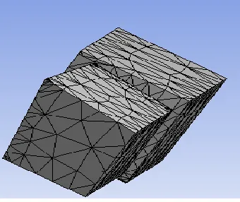
Table 3: Forces obtained with Soft Materials
S. No Depth of Cut
Forces
FX FY FZ
1. 0.5 17.14669 11.43113 57.15565
2. 1 34.29339 22.86226 114.3113
3. 1.5 51.44008 34.29339 171.4669
4. 2 68.58678 45.72452 228.6226
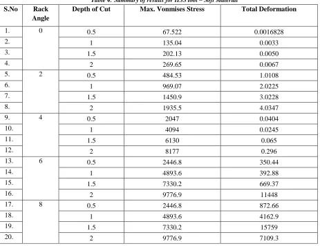
Figure 2 shows the graphical representation of above results.
Figure 2: Graphical Representations of Forces generated in cutting tools with Soft Material
Table 3: Forces obtained with Hard Materials
S. No Depth of Cut
Forces
FX FY FZ
1. 0.5 19.2043 12.80286 64.01432
2. 1 38.40859 25.60573 128.0286
3. 1.5 57.61289 38.40859 192.043
4. 2 76.81719 51.21146 256.0573
Figure 3 shows the graphical representation of above results.
1.71E+01
3.43E+01
5.14E+01
6.86E+01
1.14E+01 2.29E+01
3.43E+01 4.57E+01
5.72E+01
1.14E+02
1.71E+02
2.29E+02
0.00E+00 5.00E+01 1.00E+02 1.50E+02 2.00E+02 2.50E+02
CASE 1 (0.5) CASE 2 (1) CASE 3 (1.5) CASE 4 (2)
Figure 3: Graphical Representations of Forces generated in cutting tools with Hard Material
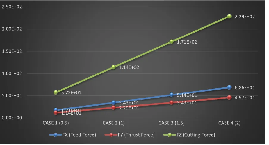
Summary of results for HSS tool – soft material is presented as follows.
Table 4: Summary of results for HSS tool – Soft Material
1.92E+01
3.84E+01
5.76E+01
7.68E+01
1.28E+01 2.56E+01
3.84E+01 5.12E+01
6.40E+01
1.28E+02
1.92E+02
2.56E+02
0.00E+00 5.00E+01 1.00E+02 1.50E+02 2.00E+02 2.50E+02 3.00E+02
CASE 1 (0.5) CASE 2 (1) CASE 3 (1.5) CASE 4 (2)
FX (Feed Force) FY (Thrust Force) FZ (Cutting Force)
S.No Rack Angle
Depth of Cut Max. Vonmises Stress Total Deformation
1. 0 0.5 67.522 0.0016828
2. 1 135.04 0.0033
3. 1.5 202.13 0.0050
4. 2 269.65 0.0067
5. 2 0.5 484.53 1.0108
6. 1 969.07 2.0225
7. 1.5 1450.9 3.0228
8. 2 1935.5 4.0347
9. 4 0.5 2047 0.0404
10. 1 4094 0.0245
11. 1.5 6130 0.065
12. 2 8177 0.296
13. 6 0.5 2446.8 350.44
14. 1 4893.6 392.88
15. 1.5 7330.2 669.37
16. 2 9776.9 11448
17. 8 0.5 2446.8 872.66
18. 1 4893.6 4162.9
19. 1.5 7330.2 15759
Graphical representations of above results are as follows.
Figure 4: Stress Analysis for HSS-Soft Material
Figure 5: Deformation Analysis for HSS-Soft Material
Summary of results for HSS tool – Hard material are presented as follows.
Table 5: Summary of results for HSS tool – Hard Material
0 2000 4000 6000 8000 10000 12000
0 DEGREE 2 DEGREE 4 DEGREE 6 DEGREE 8 DEGREE
0.5
1
1.5
2
0 2000 4000 6000 8000 10000 12000 14000 16000 18000
0 DEGREE 2 DEGREE 4 DEGREE 6 DEGREE 8 DEGREE
0.5
1
1.5
2
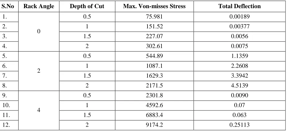
S.No Rack Angle Depth of Cut Max. Von-misses Stress Total Deflection
1.
0
0.5 75.981 0.00189
2. 1 151.52 0.00377
3. 1.5 227.07 0.0056
4. 2 302.61 0.0075
5.
2
0.5 544.89 1.1359
6. 1 1087.1 2.2608
7. 1.5 1629.3 3.3942
8. 2 2171.5 4.5139
9.
4
0.5 2301.8 0.0090
10. 1 4592.6 0.07
11. 1.5 6883.4 0.063
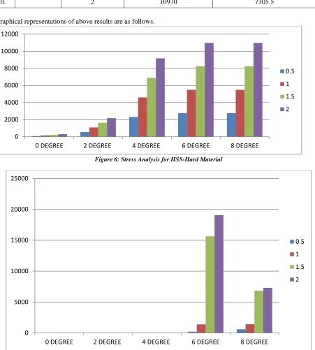
Graphical representations of above results are as follows.
Figure 6: Stress Analysis for HSS-Hard Material
Figure 7: Deformation Analysis for HSS-Hard Material
0 2000 4000 6000 8000 10000 12000
0 DEGREE 2 DEGREE 4 DEGREE 6 DEGREE 8 DEGREE
0.5
1
1.5
2
0 5000 10000 15000 20000 25000
0 DEGREE 2 DEGREE 4 DEGREE 6 DEGREE 8 DEGREE
0.5
1
1.5
2
13.
6
0.5 2750.1 207.39
14. 1 5489.9 1379
15. 1.5 8229.8 15633
16. 2 10970 19062
17.
8
0.5 2750.1 597.72
18. 1 5489.9 1416.1
19. 1.5 8229.8 6814.3
Summary of results for CBN tool – Soft Material are presented as follows.
Table 6: Summary of results for CBN tool – Soft Material
Graphical representations of above results are as follows.
Figure 8: Stress Analysis for CBN-Soft Material
0 2000 4000 6000 8000 10000 12000
0 DEGREE 2 DEGREE 4 DEGREE 6 DEGREE 8 DEGREE
0.5
1
1.5
2
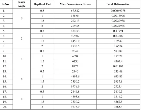
S.No Rack
Angle Depth of Cut Max. Von-misses Stress Total Deformation
1.
0
0.5 67.522 0.00069978
2. 1 135.04 0.0013996
3. 1.5 202.13 0.0020938
4. 2 269.65 0.0027935
5.
2
0.5 484.53 0.41991
6. 1 969.07 0.83809
7. 1.5 1450.9 1.2542
8. 2 1935.5 1.6674
9.
4
0.5 2047 58.889
10. 1 4094 157.22
11. 1.5 6130 4367.4
12. 2 8177 0.01102
13.
6
0.5 2446 133.49
14. 1 4893.6 653.83
15. 1.5 7330.2 3937.9
16. 2 9776.9 2723.4
17.
8
0.5 2446.8 3410.5
18. 1 4893.6 3314.2
19. 1.5 7330.2 4367.5
Figure 9: Deformation Analysis for CBN-Soft Material
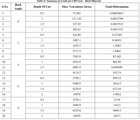
Summary of results for CBN tool – hard material presented as follows.
Table 8: Summary of results for CBN tool – Hard Material
0 500 1000 1500 2000 2500 3000 3500 4000 4500 5000
0 DEGREE 2 DEGREE 4 DEGREE 6 DEGREE 8 DEGREE
0.5
1
1.5
2
S.No Rack
Angle Depth Of Cut Max. Von-misses Stress Total Deformation
1.
0
0.5 75.981 0.00078813
2. 1 151.152 0.0015706
3. 1.5 227.07 0.0023532
4. 2 302.61 0.0031357
5.
2
0.5 544.89 0.47349
6. 1 1087.1 0.94031
7. 1.5 1629.3 1.4082
8. 2 2171.5 1.8801
9.
4
0.5 2301.8 83.265
10. 1 4592.6 801.06
11. 1.5 6883.4 0.048589
12. 2 9174.2 5517.9
13.
6
0.5 2750.1 899.19
14. 1 5489.9 2816.5
15. 1.5 8229.8 673.44
16. 2 10970 1100.6
17.
8
0.5 2750.1 21.94
18. 1 5489.9 11611
19. 1.5 8229.8 5049.5
Graphical representations of above results are as follows.
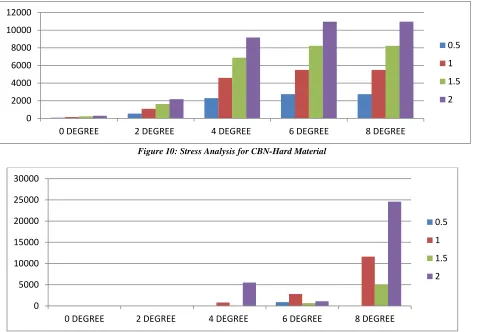
Figure 10: Stress Analysis for CBN-Hard Material
Figure 11: Deformation Analysis for CBN-Hard Material
Discussion
From force analysis one can analyze that for both soft and hard materials forces on tools tend to have same nature. Figure 5.2 and Figure 5.3 show that thrust forces have minimum, feed forces have intermediate and cutting forces have the maximum effect on the cutting tool. From same figures one can find that amount of cutting forces contributes almost double as compared to other two components. Figures also indicate that all the three forces increase as depth of cut increases. As depth of cut increases difference in magnitude of cutting force as compared to other two component increases. This difference causes unbalancing in the tool due to which tool failure occurs. Thus in order to keep the cutting tool safe, this difference can be kept minimum, by using considerably less depth of cut.
On the analysis of stresses and total deformation from HSS – soft material combination it was found that von-misses stresses increases with increasing rack angle from 0 degrees to 8 degrees and with depths of cut. Results shows similarity of scores of von misses stresses for 6 degrees and 8 degrees rack angles. Moreover, deformations at 6 degree rack angle at depths of cut of 0.5 mm, 1 mm and 1.5 mm are lesser as compared to those at 8 degrees. For other angles negligible deformation was found, but due to lesser amount of cutting forces these angles are not suitable. In this combination, for lesser depths of cut 6 degree angles can be preferred as compared to 8 degree angles.
On analyzing the stresses and total deformations for HSS – hard material combination it was also found that von-misses stresses increases with increasing rack angle from 0 degrees to 8 degrees and with depths of cut. Results
0 2000 4000 6000 8000 10000 12000
0 DEGREE 2 DEGREE 4 DEGREE 6 DEGREE 8 DEGREE
0.5
1
1.5
2
0 5000 10000 15000 20000 25000 30000
0 DEGREE 2 DEGREE 4 DEGREE 6 DEGREE 8 DEGREE
0.5
1
1.5
shows similarity of scores of von misses stresses for 6 degrees and 8 degrees rack angles. In this case comparatively lesser values of total deformation were found at 8 degrees for high depth of cut. So, in these cases, 8 degree angles can be preferred.
Analysis of CBN – soft material combination also shows that von-misses stresses increases with increasing rack angle from 0 degrees to 8 degrees and with depths of cut. Results shows similarity of scores of von misses stresses for 6 degrees and 8 degrees rack angles. Results also report that at 6 degrees rack angle with 0.5 mm and 1 mm depths of cut values of total deformation are less as compared to those at 8 degrees with similar depths of cut. At 2 mm depth of cut deformation is also lesser than similar value at 6 degree and 2 mm depth of cut. So therefore, in such cases, for lesser depths of cut 6 degree rack angles can be preferred.
Combination of CBN-hard material also shows that von-misses stresses increases with increasing rack angle from 0 degrees to 8 degrees and with depths of cut. Results shows similarity of scores of von misses stresses for 6 degrees and 8 degrees rack angles. While considering deformations, results show that total deformations in the tool are very less at 6 degrees as compared to 8 degrees rack angles, due to which these angles can be preferred in order to avoid tool failure.
CONCLUSION, LIMITATIONS AND FUTURE SCOPE OF THE RESEARCH
Present section is devoted to conclusion, limitations and future scope of the research work, the details of which are presented in upcoming sections.
Conclusion
Following are the conclusions drawn out of the research work.
1. Results of Force Analysis
a) During machining, cutting forces contribute greatest proportion as compared to feed forces and thrust
forces;
b) Magnitude of these forces increases with increasing depth of cut; and
c) In order to keep the tool safe difference between these forces should be kept minimum.
2. Results of Stress and Deformation Analysis
a) Von - misses stresses increases with increase in rack angle and depths of cut, irrespective of type of job
material and tool material;
b) At 1.5 mm and 2 mm depths of cut, von-misses stresses show same intensity, but value of deformations
changes which depends on the type of materials used for tooling and job;
Limitations and Future Scope of the Research
Following are the limitations and associated future scope of the present research work.
1. The research work is limited to single point cutting tools only;
2. Present research work is limited to particular sets of job and tool materials; and
3. The research work is also limited to particular sets of rack angles and depths of cut changes.
Following points indicate the future scope of the research work.
1. An extensive research in the field of multi point cutting tools is still pending;
2. A comprehensive research work considering a vast set of tool and job materials can be undertaken; and
3. A detailed research considering more than one tool parameters and detailed set of depths of cut is can also be
REFERENCES
1. Garcia-Gonzalez, J. C., Moscoso-Kingsley, W., & Madhavan, V. (2016). Rake faces temperature when machining with coated cutting tools. Procedia Manufacturing, 5, 815-827.
2. Koleva, S., Enchev, M., & Szecsi, T. (2015). Automatic dimension measurement on CNC lathes
using the cutting tool. Procedia CIRP, 33, 568-575.
3. Liu, R., Eaton, E., Yu, M., & Kuang, J. (2017). An Investigation of Side Flow during Chip Formation in Orthogonal Cutting. Procedia Manufacturing, 10, 568-577.
4. Lu, N., Li, Y., Liu, C., & Mou, W. (2016). Cutting Tool Condition Recognition in NC Machining
Process of Structural Parts Based on Machining Features. Procedia CIRP, 56, 321-325.
5. Orlowski, K. A., Ochrymiuk, T., Sandak, J., & Sandak, A. (2017). Estimation of fracture toughness and shear yield stress of orthotropic materials in cutting with rotating tools. Engineering Fracture Mechanics, 178, 433-444.