University of Pennsylvania
ScholarlyCommons
Publicly Accessible Penn Dissertations
1-1-2016
From Verified Models to Verified Code for Safe
Medical Devices
Zhihao Jiang
University of Pennsylvania, [email protected]
Follow this and additional works at:http://repository.upenn.edu/edissertations Part of theComputer Sciences Commons
This paper is posted at ScholarlyCommons.http://repository.upenn.edu/edissertations/1786
For more information, please [email protected].
Recommended Citation
Jiang, Zhihao, "From Verified Models to Verified Code for Safe Medical Devices" (2016).Publicly Accessible Penn Dissertations. 1786.
From Verified Models to Verified Code for Safe Medical Devices
Abstract
Medical devices play an essential role in the care of patients around the world, and can have a life-saving effect. An emerging category of autonomous medical devices like implantable pacemakers and implantable
cardioverter defibrillators (ICD) diagnose conditions of the patient and autonomously deliver therapies. Without trained professionals in the loop, the software component of autonomous medical devices is responsible for making critical therapeutic decisions, which pose a new set of challenges to guarantee patient safety. As regulation effort to guarantee patient safety, device manufacturers are required to submit evidence for the safety and efficacy of the medical devices before they can be released to the market. Due to the closed-loop interaction between the device and the patient, the safety and efficacy of autonomous medical devices must ultimately be evaluated within their physiological context. Currently the primary closed-loop validation of medical devices is in form of clinical trials, in which the devices are evaluated on real patients. Clinical trials are expensive and expose the patients to risks associated with untested devices. Clinical trials are also
conducted after device development, therefore issues found during clinical trials are expensive to fix.
There is urgent need for closed-loop validation of autonomous medical devices before the devices are used in clinical trials. In this thesis, I used implantable cardiac devices to demonstrate the applications of model-based approaches during and after device development to provide confidence towards the safety and efficacy of the devices. A heart model structure is developed to mimic the electrical behaviors of the heart in various heart conditions. The heart models created with the model structure are capable of interacting with implantable cardiac devices in closed-loop and can provide physiological interpretations for a large variety of heart conditions. With the heart models, I demonstrated that closed-loop model checking is capable of identifying known and unknown safety violations within the pacemaker design. More importantly, I developed a
framework to choose the most appropriate heart models to cover physiological conditions that the pacemaker may encounter, and provide physiological context to counter-examples returned by the model checker. A model translation tool UPP2SF is then developed to translate the pacemaker design in UPPAAL to Stateflow, and automatically generated to C code. The automated and rigorous translation ensures that the properties verified during model checking still hold in the implementation, which justifies the model checking effort. Finally, the devices are evaluated with a virtual patient cohort consists of a large number of heart models before evaluated in clinical trials. These in-silico pre-clinical trials provide useful insights which can be used to increase the success rate of a clinical trial. The work in this dissertation demonstrated the importance and challenges to represent physiological behaviors during closed-loop validation of autonomous medical devices, and demonstrated the capability of model-based approaches to provide safety and efficacy evidence during and after device development.
Degree Type
Dissertation
Degree Name
Doctor of Philosophy (PhD)
Graduate Group
First Advisor
Rahul Mangharam
Keywords
Cyber-Physical Systems, in-silico Pre-clinical Trials, Medical Device Validation, Model Checking
Subject Categories
FROM VERIFIED MODELS TO VERIFIED CODE FOR SAFE MEDICAL DEVICES
Zhihao Jiang
A DISSERTATION
in
Computer and Infomation Science
Presented to the Faculties of the University of Pennsylvania in Partial Fulfillment of the Requirements for the
Degree of Doctor of Philosophy
2016
Rahul Mangharam, Associate Professor of Electrical and Systems Engineering Supervisor of Dissertation
Lyle Ungar, Professor of Computer and Information Science Graduate Group Chairperson
Dissertation Committee:
Rajeev Alur (Chair), Zisman Professor of Computer and Information Science Insup Lee, Cecilia Fitler Moore Professor of Computer and Information Science Oleg Sokolsky, Research Associate Professor of Computer and Information Science Pieter J. Mosterman, Adjunct Professor at the School of Computer Science at McGill University
FROM VERIFIED MODELS TO VERIFIED CODE FOR SAFE MEDICAL DEVICES
COPYRIGHT
2016
Acknowledgments
I’m most grateful to my dissertation advisor, Prof. Rahul Mangharam, for his guid-ance and support throughout my dissertation research. It was my great pleasure to work with him.
I am grateful to Dr. Sanjay Dixit from the Hospital of University of Pennsylvania who shared physiological knowledge which is the backbone of my dissertation.
I would like to express my gratitude to Prof. Insup Lee, Prof. Rajeev Alur and Prof. Oleg Sokolsky for their continuous support and encouragement to my research over the years.
I would like to thank Dr. Pieter J. Mosterman who provided me with valuable insight on model-based design.
I am thankful to Dr. Richard Gray for providing suggestions to my research from the regulatory perspective.
ABSTRACT
FROM VERIFIED MODELS TO VERIFIED CODE FOR SAFE MEDICAL DEVICES
Zhihao Jiang Rahul Mangharam
Medical devices play an essential role in the care of patients around the world, and can have a life-saving effect. An emerging category of autonomous medical devices like implantable pacemakers and implantable cardioverter defibrillators (ICD) diag-nose conditions of the patient and autonomously deliver therapies. Without trained professionals in the loop, the software component of autonomous medical devices is responsible for making critical therapeutic decisions, which pose a new set of chal-lenges to guarantee patient safety. As regulation effort to guarantee patient safety, device manufacturers are required to submit evidence for the safety and efficacy of the medical devices before they can be released to the market. Due to the closed-loop interaction between the device and the patient, the safety and efficacy of autonomous medical devices must ultimately be evaluated within their physiological context. Cur-rently the primary closed-loop validation of medical devices is in form of clinical trials, in which the devices are evaluated on real patients. Clinical trials are expensive and expose the patients to risks associated with untested devices. Clinical trials are also conducted after device development, therefore issues found during clinical trials are expensive to fix. There is urgent need for closed-loop validation of autonomous med-ical devices before the devices are used in clinmed-ical trials.
In this thesis, I used implantable cardiac devices to demonstrate the applications of model-based approaches during and after device development to provide confidence towards the safety and efficacy of the devices.
A heart model structure is developed to mimic the electrical behaviors of the heart in various heart conditions. The heart models created with the model structure are capable of interacting with implantable cardiac devices in closed-loop and provide physiological interpretation for a large variety of heart conditions
With the heart models, I demonstrated that closed-loop model checking is capable of identifying known and unknown safety violations within the pacemaker design. More importantly, I developed a framework to choose the most appropriate heart models to cover physiological conditions that the pacemaker may encounter, and provide physiological context to counter-examples returned by the model checker.
A model translation tool UPP2SF is then developed to translate the pacemaker design in UPPAAL to Stateflow, and automatically generated to C code. The au-tomated and rigorous translation ensures that the properties verified during model checking still hold in the implementation, which justifies the model checking effort.
trials provide useful insights which can be used to increase the success rate of a clinical trial.
Contents
Title i
Acknowledgments iv
Abstract v
Contents vii
List of Tables xi
List of Figures xii
1 Medical Devices: Current State and Challenges 1
1.1 Closing the Device-Patient Loop . . . 2
1.1.1 Challenges for Developing Autonomous medical Devices . . . . 3
1.2 Medical Device Regulation Efforts and Challenges . . . 5
1.2.1 Guidelines During Device Development . . . 5
1.2.2 Pre-Market Evaluation with Clinical Trials . . . 6
1.2.3 Lack of Closed-loop Validation During and After Device Devel-opment . . . 7
1.3 Model-based Design and Pre-certification of Medical Devices . . . 7
1.4 Contributions . . . 8
1.5 Useful terminologies for often misinterpreted terms . . . 10
1.5.1 Requirements vs. Specifications . . . 10
1.5.2 Validation vs. Verification vs. Testing . . . 10
1.5.3 Closed-loop vs. Open-loop Evaluation . . . 11
2 A Motivating Example: A Dual Chamber Pacemaker Design 12 2.1 Physiology Basis of the Heart and the Pacemaker . . . 12
2.1.1 Blood Circulation System . . . 12
2.1.2 Electrical Conduction System of the Heart . . . 13
2.1.3 Electrophysiology and Implantable Cardiac Devices . . . 14
2.2.1 Post Ventricular Atrial Refractory Period (PVARP) and Post
Ventricular Atrial Blanking (PVAB) . . . 16
2.2.2 Ventricular Refractory Period (VRP) . . . 16
2.3 Identify Hazards in the Dual Chamber Pacemaker Design . . . 17
2.3.1 Endless-Loop Tachycardia . . . 17
2.3.2 Atrial Tachycardia Response . . . 18
2.4 Discussion . . . 19
3 Theme 1: Modeling the Physiological Environment 20 3.1 Related Work . . . 20
3.2 EP Heart Model Structure for Closed-loop Validation of Implant-able Cardiac Devices . . . 21
3.2.1 Timing Behaviors of Cellular Electrophysiology . . . 23
3.2.2 Heart Model Components . . . 24
3.2.3 Modeling the Heart’s Electrical Conduction System . . . 26
3.3 Interaction with the Heart Model . . . 26
3.3.1 Probe Model for Synthetic EGM Generation . . . 26
3.3.2 Pacemaker Oversensing and Crosstalk . . . 27
3.3.3 Lead Displacement . . . 28
3.4 Heart-on-a-Chip Platform . . . 29
3.5 EP Heart Model Validation . . . 32
3.5.1 Validating Models for Closed-loop Simulation . . . 32
3.5.2 Validating Models for Closed-loop Model Checking . . . 33
3.6 EP Heart Model Identification . . . 35
3.6.1 Heart Model Identification for Closed-loop Testing . . . 37
3.7 Discussion . . . 38
4 Theme 2: Closed-loop Model Checking for Implantable Pacemaker 39 4.1 Related Work . . . 39
4.2 Model of A Dual Chamber pacemaker . . . 41
4.2.1 Timed Automata . . . 41
4.2.2 UPPAAL Model of a Dual Chamber Pacemaker . . . 42
4.3 Heart Models for Closed-loop Model Checking . . . 42
4.3.1 Covering More Behaviors With Over-approximation . . . 44
4.3.2 Counter-Example-Guided Abstraction Refinement . . . 44
4.3.3 Abstraction Tree for Heart Model Abstraction Refinement . . 45
4.4 Efficacy Validation for Implantable Pacemaker . . . 53
4.5 Safety Validation for Implantable Pacemaker . . . 55
4.5.1 Terminating Endless Loop Tachycardia . . . 57
4.5.2 Mode Switch Operation: Atrial Tachycardia Response . . . 59
5 Theme 3: Verified Model to Verified Code 62
5.1 Related Work . . . 62
5.2 A Brief Overview of UPPAAL . . . 63
5.2.1 UPPAAL Modeling of Real-time Systems . . . 63
5.3 Extracting Runs from UPPAAL Models . . . 66
5.4 Brief Overview of Stateflow . . . 68
5.5 UPP2SF: Model Translation Procedure . . . 69
5.5.1 Overview of UPP2SF . . . 70
5.5.2 Mapping UPPAAL Edges Without Synchronization . . . 71
5.5.3 Obtaining an MPA Execution of the Chart . . . 73
5.5.4 Translating Broadcast Channels . . . 73
5.5.5 Translating Urgent and Committed States . . . 74
5.5.6 Stateflow Chart Optimization . . . 75
5.6 Correctness of the Translation Procedure . . . 75
5.7 Pacemaker Stateflow Design . . . 79
5.7.1 Decoupling the Controller and Environment . . . 81
5.8 Stateflow Model Validation . . . 82
5.9 Pacemaker Implementation . . . 83
5.9.1 Platform Implementation . . . 85
5.9.2 Decoupling the Controller and the Environment . . . 86
5.9.3 Worst Case Execution Time Estimation in UPPAAL . . . 87
5.10 Testing of the Physical Implementation . . . 88
5.11 Discussion . . . 90
6 Theme 4: in-silico Pre-clinical Trials for Implantable Cardiac De-vices 91 6.1 Clinical trials and RIGHT . . . 93
6.1.1 The RIGHT trial . . . 93
6.2 Virtual Cohort Generation . . . 95
6.2.1 Timing Model . . . 95
6.2.2 Morphology Model . . . 96
6.2.3 Patient Data Adjudication and EGM Template Extraction . . 97
6.2.4 Cohort generation . . . 98
6.3 Implementing Device Algorithms . . . 99
6.3.1 Cardiac Signal Sensing . . . 99
6.3.2 VT Detection Algorithm . . . 100
6.3.3 Validation . . . 101
6.4 Results . . . 102
6.4.1 The rate of inappropriate therapy . . . 102
6.4.2 Condition-level rates . . . 103
6.4.3 Effect of Device Parameters on Discriminating Capability . . . 105
7 Conclusion 109
List of Tables
5.1 Mapping UPPAAL conditions over clocks into Stateflow . . . 72 5.2 Mapping UPPAAL edges from automatonPk into Stateflow transitions 74
5.3 Pacemakers parameters. . . 83 5.4 Execution times for the pacemaker procedure; OL denotes open-loop,
without inputs from the signal generator. . . 86 5.5 Results of the tests performed on the setup from Fig. 5.6. . . 89
List of Figures
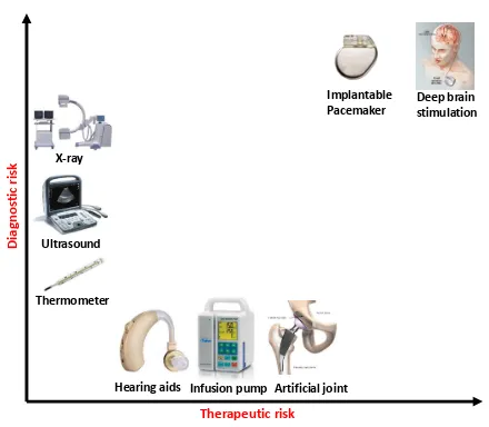
1.1 Current medical devices across a range of diagnostic and therapeutic risk. Implantable software-controlled devices such as the pacemaker and defibril-lator which operate in a closed-loop of sensing, control and actuation are amongst the highest risk . . . 2 1.2 Diagnostic-only and therapy-only devices do not interact with the patient
in direct closed-loop. The physician is responsible for the diagnostic and/or therapeutic decisions. However in closed-loop medical devices, the devices interact with the patient in closed-loop and have to make therapeutic deci-sions based on their own diagnosis.. . . 3 1.3 Medical device recalls due to software issues have risen from 10% in the
1990s to ˜15% in the past decade (U.S.FDA [2012]) . . . 5 1.4 International standards for medical device safety. These standards define
the required activities during the development process. . . 6 1.5 Percentage of computer simulation is expected to increase as safety and
effectiveness evidence of medical devices (http://mdic.org/) . . . 8 1.6 Model-based design for implantable cardiac devices with closed-loop validation 9 1.7 Validation activities during the software development life cycle (D A.
Vogel [2011]) . . . 11
2.1 (a) The circulation system (http://revisionworld.com/). (b) Electrical Con-duction system of the heart . . . 13 2.2 (a) Lead placement for a dual chamber pacemaker. (b) Electrogram (EGM)
signals measured from pacemaker leads and corresponding internal pace-maker events . . . 14 2.3 Basic 5 timing cycles for a dual chamber pacemaker which include
the Lower Rate Interval (LRI), Atrio-Ventricular Interval (AVI), and Upper Rate Interval (URI). Also included are the blanking intervals, Post Ventricular Atrial Refractory Period (PVARP) and Ventricular Refractory Period (VRP), to inhabit action by the pacemaker. . . 16 2.4 Fault Tree Analysis (FTA) for two failures of a pacemaker. . . 17 2.5 Endless Loop Tachycardia case study demonstrating the situation when
2.6 Benign open loop case: SVT without a pacemaker or with a pacemaker in sense-only mode (ODO) (b) Dangerous closed-loop-case SVT with DDD pacemaker which tries to match the fast atrial rate with a corresponding (and dangerous) fast ventricular rate. . . 19
3.1 Physiological models of the heart from different perspectives . . . 21 3.2 (a) The generation of Action potential; (b) Action potential; (c1) The
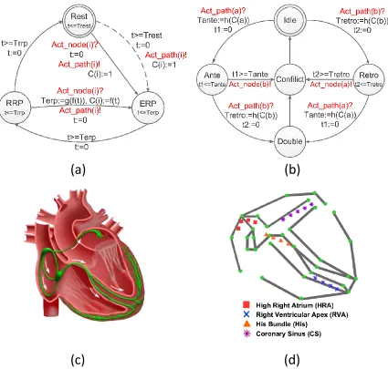
second activation arrived during ERP; (c2) Arrived during RRP; (c3) Arrived after refractory. . . 23 3.3 (a) Node automaton: The dotted transition is only valid for tissue (like
SA node) that can be activated by an external trigger; (b) Path automa-ton modeling the electric conduction and propagation between two node automata; (c) Electrical conduction system of the heart; (d) Model of the electrical conduction system of the heart using a network of node & path automata ( Jiang et al. [2012a]). . . 25 3.4 The influence of conduction velocity and probe configuration on the
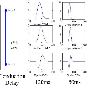
EGM morphology. The left columns show the placement of probes in relation to the path; the right columns show the functional EGM. . . 27 3.5 Crosstalk between pacemaker leads with high sensitivity in the
ventri-cle, adjusted sensitivity and ventricular safety pacing . . . 28 3.6 (a) Dotted line shows the location where the atrial lead should be (b)
Pace-maker function before lead dislodge. (c) PacePace-maker function after lead dislodge 29 3.7 The heart model was developed in Matlab/Simulink and code was
auto-matically generated to operate on an FPGA platform for platform-level testing. . . 30 3.8 Heart-on-a-Chip testbed for real-time closed-loop testing of the
pace-maker or model of the pacepace-maker with the heart model on the hardware platform . . . 31 3.9 (a) Probe locations for a general EP testing procedure. (b) EGM signals
measured from the probes at the high right atrial (HRA), His bundle (HBE) and right ventricular apex (RVA) standard catheter positions . . . 33 3.10 Key interval values when the coupling interval shortens for (a) a real patient
(Josephson [2008]) and (b) in heart model simulation (Jiang et al. [2010b]). 34 3.11 (a) Electrograms of induced Wenckebach block in a patient. (b)
3.12 Simulation model of the heart showing the conduction pathways (left) with electrogram signals from different probe locations (right) and an interactive pacing panel (bottom left). In this case, the heart was paced four times at an interval of 500ms, followed by a pacing at a shorter (250ms) interval. This EP Testing procedure is employed to trigger conduction along alternative pathways and check for the existence of
a reentry circuit. . . 36
3.13 (a) The illustration of the probe locations. (b) Multiple pacing sequences with different timing outcomes. (c) The heart model with undecided pa-rameters . . . 36
3.14 Timing intervals measured during clinical studies (Josephson [2008]) . . . 38
4.1 Five basic timing cycles for a dual chamber pacemaker, which include the Lower Rate Interval (LRI), Atrio-Ventricular Interval (AVI), and Upper Rate Interval (URI). Also included are the blanking intervals, Post Ventricular Atrial Refractory Period (PVARP) and Ventricular Refractory Period (VRP), to inhabit action by the pacemaker. . . 43
4.2 (a) Device modeling with CEGAR framework (b) Closed-loop model check-ing with environment abstraction tree. . . 45
4.3 Node and Path Automata which models the timing properties of the heart tissue. A network of node and path automata models the generation and conduction of electrical activities of a heart . . . 46
4.4 Examples of the initial set of heart models. The models are different in node and path topology and/or timing parameters. . . 47
4.5 Rule R1: Remove reentry circuits from the model . . . 48
4.6 Rule R2: Remove non-essential structures . . . 49
4.7 Rule R4: Merging parameter ranges . . . 49
4.8 Rule R6 application example: the blocking property ofN13 is fulfilled by a non-deterministic conduction path P21 . . . 50
4.9 Rule R7 application example: The conduction property of P21 is replaced by self activation ofN31 and N32 . . . 52
4.10 One example of abstraction tree of heart models . . . 54
4.11 (a) Monitor for LRL: Interval between two ventricular events should be less than TLRI, (b) Monitor for URL: Interval between a ventricular event and a VP should be longer than TURI . . . 54
4.12 UPPAAL monitor for Property 1. . . 55
4.14 (1) The componentPVAS sends VP AS! event when a VP-AS pattern with delay between [150,200] is detected; (2) Component ELTct. After 8 VP-AS pattern, the algorithm increase TPVARP to 500ms. (3) Modified PVARP’ component. TPVARP can only be set to 500 for one timing cycle. . . 57 4.15 (a) After switching to VDI mode, the new LRI component LRI’ maintains
a minimum V-V interval; (b) After switching to VDI mode, the new AVI componentAVI’ keeps track of the time after each atrial events. . . 59 4.16 (1) ComponentINT: An atrial event (AS,AR) arrives beforethreshafter the
previous atrial event is regarded as a fast event. Atrial event arrives after threshandAPare regarded as slowevent; (2) ComponentCNT: After 8fast event the algorithm will start a duration by sendingdu beg and will switch to VDI mode when the duration ends (du end); (3) Component DUR:The duration length is 8 ventricular events (VS,VP) . . . 60 4.17 (a) Safety Violation: VP is delayed due to the reset of timer during
mode-switch, (b) Efficacy Violation: The blocking period may block some atrial events, turning two Fast events to one Slow event (Jiang et al. [2012b]) . . . 61
5.1 An UPPAAL model example. . . 65 5.2 Structure of Stateflow charts derived by UPP2SF. Parent statesP1, ..., Pn
are derived from automata, while the clock states Gc x1, ..., Gc xm
model all global clocks x1, ..., xm from the UPPAAL model. The state
Eng is used to control execution of the chart. . . 71 5.3 Pacemaker Stateflow chart extracted using UPP2SF from the UPPAAL
model in Fig. 4.1; the heart and buffer models are highlighted. . . 80 5.4 Test points for behavioral real-time constraints. . . 82 5.5 Structure of the pacemaker code obtained from the Stateflow chart
shown in Fig. 5.3. . . 84 5.6 Hardware setup with MSP430F5438 experimenters board. . . 86 5.7 Transition monitors (TrMonitor) used for the worst-case execution
time estimation. . . 88 5.8 A test screen shot for property B4.2; clk pulses are highlighted. . . . 89
6.1 Bringing a device to market. Clinical trials are the last step before a new device’s market approval. Model-based clinical trials will provide insight during planning and execution of clinical trials, leading to reduction in costs and increasing the chance of a successful trial. . . 92 6.2 ICD connected to the heart. The atrial, ventricular, and shock
6.4 EGM waveform generation. From a given model instance and set of tachy-cardias, an EGM waveform is generated for the duration of an episode. The timing model determines event timings. When an event occurs, the EGM morphology for the event is output from the morphology model. . . 97 6.5 (Left) The EGM record is segmented into episodes with distinct rhythms
in each. (Right) From each episode, individual EGM morphologies are ex-tracted and stored. . . 98 6.6 SVT/VT detection algorithm by Boston Scientific (Boston Scientific
Corpo-ration [2007b]). The two cases on the right illustrate two different decisions by the algorithm. (a) illustrates a sustained VT case where at the end of the Duration, the ventricular rate is faster than the atrial rate. The algorithm correctly identified the rhythm as VT and delivered therapy. (b) illustrates a SVT case where at the end of the Duration, the ventricular rate is slower than the atrial rate. Then by comparing the EGM morphology in the Shock channel (Marker 1) with the stored NSR template (Marker 2) for the last 10 EGM events, the algorithm decided that the morphology is correlated, therefore therapy is inhibited. . . 100 6.7 Example of validation output screenshots (Ventricular fibrillation) showing
matching therapy decision for the ICD and our implementation.. . . 102 6.8 Rate of inappropriate detection (2ndand 4thcolumns) for different
Chapter 1
Medical Devices: Current State
and Challenges
The medical device market is worth $289 billion, of which $110 billion is from the US alone, with this number projected to reach $133 billion in 2016 (Research and Markets [2015]). Examples include everything from adhesive bandages, stents, artificial joints, drug infusion pumps to surgical robots, implantable cardiac pacemakers, and devices still undergoing basic research like the artificial pancreas. To take one example of the societal impact of medical devices, an estimated 3 million people worldwide have implanted cardiac pacemakers (a heart rate management device), with 600,000 added annually. Clinical trials have presented evidence that patients implanted with cardiac defibrillators (another heart rate management device) have a mortality rate reduced by up to 31% (Moss et al. [2012]).
The US Food and Drug Administration (FDA) defines a medical device as an instrument, apparatus, implement, machine, or implant which is:
• intended for use in the diagnosis of disease or other conditions, or in the cure, mitigation, treatment, or prevention of disease, in humans or other animals, or
• intended to affect the structure or any function of the human body or other ani-mals, and which does not achieve any of its primary intended purposes through chemical action and which is not dependent upon being metabolized for the achievement of any of its primary intended purposes.”
X-ray
Ultrasound
Thermometer
Hearing aids Infusion pump Artificial joint
Implantable
Pacemaker Deep brainstimulation
Therapeutic risk
Dia
gnos
tic
risk
Figure 1.1: Current medical devices across a range of diagnostic and therapeutic risk. Im-plantable software-controlled devices such as the pacemaker and defibrillator which operate in a closed-loop of sensing, control and actuation are amongst the highest risk
1.1
Closing the Device-Patient Loop
Medical
Device Patient
Physician
Medical
Device Patient
Physician
Medical
Device Patient
Physician
(a) Diagnose-only (b) Therapy-only (c) Closed-loop
Therapy Sense Operate Follow-up
Figure 1.2: Diagnostic-only and therapy-only devices do not interact with the patient in direct closed-loop. The physician is responsible for the diagnostic and/or therapeutic de-cisions. However in closed-loop medical devices, the devices interact with the patient in closed-loop and have to make therapeutic decisions based on their own diagnosis.
it operates as instructed by the physicians.
There is a class of devices with both diagnostic and therapeutic functions, i.e. im-plantable cardiac devices to treat cardiac arrhythmia, deep brain stimulation devices (Coffey [2009]) to treat Parkinson’s disease and artificial pancreas to treat Type-1 diabetes. These devices capture and diagnose the patient’s physiological conditions from patient signals, and deliver therapy in response (Fig. 1.2.(c)). These devices usually operate autonomously with very little human intervention. We denote them as Autonomous Medical Devices. The benefits of autonomous medical devices are timely therapy and more independent life-style. However, autonomy of these medical devices also brings about safety and efficacy concerns. With open-loop med-ical devices, the diagnosis and therapy decisions are made by medmed-ical professionals, who have expert knowledge of human physiology. Therefore they are able to identify adverse health conditions and adjust the therapy accordingly. On the other hand, closed-loop medical devices have to make both the diagnosis and therapy decisions on their own. The domain expertise required to make those decisions has to be pro-grammed into the device. It is not feasible to encode all the knowledge of human physiology into the device. For unanticipated physiological conditions, when the ap-propriate response has not been programmed into the device, the device may deliver inappropriate therapy which can have an adverse effect on patient’s health. There-fore, these devices are usually classified into the highest risk category and undergo the most stringent regulation.
1.1.1
Challenges for Developing Autonomous medical
De-vices
Physiological Complexity
Human physiology is complex and not completely understood. For instance, the functionality of the heart can be interpreted from multiple perspectives: from its electrical activity, mechanical contractions of the heart muscles, and dynamics of blood flow. The physiology of the heart can also be analyzed with multiple scales: from the molecular level to cellular level all the way to the organ and system level. It is impossible to encode all these contexts into the device, hence inappropriate diagnosis and therapy are observed due to the lack of physiological contexts ( Sandler et al. [2010], Hauser and Maron [2005]).
Physiological Variability
Physiological conditions and parameters demonstrate different levels of variability both within the individual at different times, levels of exertion and under the in-fluence of medication and also across individuals. For instance, a segment of the population may have additional electrical conduction pathways within their heart, which makes them vulnerable to certain heart diseases. Consequently, autonomous medical devices should be able to safely operate under a large variety of physiological conditions. This is difficult to guarantee, as the device designer must consider all possible physiological conditions, and their interaction with the device, during the development of the device.
Limited Observability
Autonomous medical devices normally rely on minimally invasive measurement of the physiological parameters in order to allow the patients to live their normal life. For example, implantable pacemakers and defibrillators commonly have only two leads and therefore two points of observation for the whole heart. The limited observability inevitably leads to ambiguities as different physiological conditions can map to the same input sequence to the device, resulting in inaccurate diagnosis and therapy.
Software-related Medical Device Recalls
The diagnostic and therapeutic functions of the autonomous medical devices are mostly controlled by their software components due to their complexity. For instance, implanted cardiac pacemakers and defibrillators have approximately 80,000-100,000 lines of software code which essentially makes all sensing, control and actuation de-cisions autonomously within the human body, over the 5-7 year device lifetime 1. Software embedded in a medical device, unlike electrical and mechanical components, does not fail due to corrosion, fatigue or have statistical failures of sub-components. Software failures are uniquely sourced in the design and development of the system.
1Paul L. Jones. Senior Systems/Software Engineer, Office of Science and Engineering
Software change control
Software Design
Software design manufacturing
process
Sum
% of all CDRH recalls
2008 13 141 2 156 18.3%
2009 9 111 1 121 15.4%
2010 4 73 3 80 8.9%
2011 11 182 10 203 15.8%
2012 12 169 5 186 15.5%
Sum 49 676 21 746 15.1%
Figure 1.3: Medical device recalls due to software issues have risen from 10% in the 1990s to ˜15% in the past decade (U.S.FDA [2012])
According to the US Food and Drug Administration, in 1996, 10% of all medi-cal device remedi-calls were caused by software-related issues (Maisel et al. [2001]). This percentage rose to an average of 15% of recalls from 2008 to 2012 (Fig. 1.3). Mal-functions of closed-loop medical devices usually have severe consequences, which will be categorized asClass I, meaning there is a “reasonable probability that use of these products will cause serious adverse health consequences or death.” (U.S.FDA [2006], Zhang et al. [2015], Sandler et al. [2010]).
1.2
Medical Device Regulation Efforts and
Chal-lenges
In the United States, the FDA is the primary regulatory authority responsible for assuring the safety, efficacy and security of patients using medical devices. Based on the rationale that 1) manufacturers know their devices better than the regulator, and 2) the variety of medical devices requires a variety of approaches, it is the device manufacturers’ responsibility to demonstrate the safety and efficacy of the medical devices. Manufacturers are required to complete a pre-market submission before the devices can be released to the market. The level of requirements for the submission is determined by the safety classification of the devices.
1.2.1
Guidelines During Device Development
IEC 60601-1
Medical electrical equipment safety
IEC 62304 Software development
life cycle ISO 14971
Application of risk management
ISO 80002-1 Apply ISO 14971 to medical device
software
Figure 1.4: International standards for medical device safety. These standards define the required activities during the development process.
compliance with international standards are ”recommended” in the aforementioned guidelines (Jetley et al. [2006]).
Fig. 1.4 describes the primary standards to enforce medical device safety and their relationships. The basic rationale behind these standards is that: if all the risks/hazards of the device are identified and reasonably mitigated, and the device is developed with rigorous process, the device is reasonably safe. The IEC 60601 Medical Electrical Equipment - General requirements for basic safety and essential performance is a product safety standard that all electronic medical devices must comply to. IEC 60324 specifies the processes and activities needed to perform during the software development life cycle to ensure software safety.
Risk management is a core activity throughout the software development life cy-cle. ISO 14971 is specified for the application of risk management to medical devices. In addition, for each risk management activity of ISO 14971, ISO 80002-1 provides additional guidelines for the software component, which highlights and explains ap-proaches to assuring that software safety is adequately addressed.
1.2.2
Pre-Market Evaluation with Clinical Trials
1.2.3
Lack of Closed-loop Validation During and After
De-vice Development
While formal methods are used for medical device software validation (Boston Sci-entific Corporation [2007a], Gomes and Oliveira [2009b], Jee et al. [2010a]), testing continues to be the primary method for safety and efficacy evaluation during device development. Testing for medical device software currently is ad hoc, error prone, and very expensive. Traditional methods of testing do not suffice as the test genera-tion cannot be done independently of the current state of the patient and organ. The primary approach for system-level testing of medical devices is unit testing using a playback of pre-recorded electrogram and electrocardiogram signals (Cortner [2003], Vip [2006]). This tests if the input signal triggers a particular response by the de-vice, but is unable to check how the device affects the physiological conditions of the patient.
The only closed-loop validation activity is clinical trials, which is very expensive and expose the patients to uncertified devices. Issues found during clinical trials are also expensive to fix. There is urgent need for closed-loop validation approaches during and after device development to provide safety and efficacy confidence to the device design.
1.3
Model-based Design and Pre-certification of
Medical Devices
In industries like automotive and avionics, mathematical models of the physical en-vironment that the system operates in are developed for analyzing the safety and efficacy of the control systems (or their models) (F¨urst et al. [2009], Feiler et al. [2010]). Similar approaches can potentially help during the development process of autonomous medical devices and provide extra confidence to the devices before conducting clinical trials. However, unlike man-made systems like automobiles and aircrafts, physiological systems are less understood with larger variations for the type and degree of patient conditions. The lack of faithful models of physiological envi-ronment for the autonomous medical devices is one of the reason that model-based approaches are not well-adopted in the medical device industry.
Computer
Computer Human
Human Animal
Animal
Bench
Bench
Now
Future
Figure 1.5: Percentage of computer simulation is expected to increase as safety and effec-tiveness evidence of medical devices (http://mdic.org/)
computer models and simulations are expected to play bigger role as as “regulatory-grade evidence” evidence in the development of future closed-loop medical devices (Fig. 1.5).
1.4
Contributions
In this dissertation, implantable cardiac devices are used as working examples to demonstrate how model-based approaches can help improve the safety and efficacy of autonomous medical devices during and after their development. By demonstrating the process of developing verified models to generate verified code of the devices, the results of model-based closed-loop validation can provide confidence towards the safety and efficacy of the devices.
The contribution of this dissertation is fourfold:
1. Clinical Electrophysiology heart model structure: A heart model struc-ture was developed that can represent a large variety of heart conditions and interact with implantable cardiac devices in closed-loop. The heart model struc-ture is available in both software and hardware for different applications of closed-loop validation.
2. Automated heart model abstraction and refinement: An abstraction tree structure was developed to abstract the heart models to capture the large variability of heart conditions during closed-loop model checking of implantable pacemaker, and refine the heart models to provide physiological interpretability to the counter-examples.
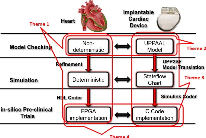
Model Checking
Simulation
in-silico Pre-clinical Trials
UPPAAL Model
Stateflow Chart
C Code implementation
UPP2SF
Model Translation
Simulink Coder
Implantable Cardiac
Device Heart
Non-deterministic
Deterministic
FPGA implementation Refinement
HDL Coder Theme 1
Theme 2
Theme 3
Theme 4
Figure 1.6: Model-based design for implantable cardiac devices with closed-loop validation
model to Stateflow model, which allows rigorous translation from model to C code.
4. in-silico Pre-clinical trials: A large virtual population of heart models was generated to evaluate the VT/SVT discrimination algorithms of Implantable Cardioverter Defibrillators before clinical trials.
Fig. 1.6 demonstrates the structure of the dissertation. The dissertation can be broken down into 4 themes, which are illustrated in Fig. 1.6.
1.5
Useful terminologies for often misinterpreted
terms
Ensuring the safety and efficacy of complex medical devices has drawn interest not only from stakeholders like regulators and industries, but also medical professionals and academia. Different communities have different interpretations over certain ter-minologies, often causing misunderstandings. In this dissertation, terminologies from the regulation perspective are adopted. Most of the definitions are referred from the FDA guideline document General Principles of Software Validation (U.S.FDA [2002]). Below are several terminologies that are used throughout the dissertation which worth clarifying.
1.5.1
Requirements vs. Specifications
By the definition of the FDA (U.S.FDA [2005]), the requirements of a system describe what the system should achieve and the specifications of a system describe how the system is designed to satisfy the requirements. For instance, a requirement for an autonomous car is ”The car should not hit objects”. The corresponding specification can be ”brake if the speed of the car is greater than x and the distance to the object is less than y”. It is obvious that a car satisfying its specification may not satisfy the requirement (e.g. when the car is driving too fast or the obstacle pops up right in front of the car). In this dissertation, the word requirement in particular denotes the intended uses of the medical devices to improve physiological conditions.
1.5.2
Validation vs. Verification vs. Testing
As defined in U.S.FDA [2002], software validation is the confirmation by examination and provision of objective evidence that:
1. software specifications conform to user needs and intended uses, and
2. the particular requirements implemented through software can be consistently fulfilled
The first aspect ensures the device is safe and effective. The second aspect maintains the traceability of requirements throughout the development life cycle. Software verification fulfills the second aspect of software validation by ”providing objective evidence that the design outputs of a particular phase of the software development life cycle meet all of the specified requirements for that phase. ”
Validation
Verification
Testing
AB
C
D
Validation activities Zone
Planning A
Requirements A
Traceability A,B
Change management A User site testing D Defect resolution A,B Risk management A
Intended use A
Evaluations B
Design reviews B
System testing C
Regression testing C,D
Figure 1.7: Validation activities during the software development life cycle (D A. Vogel [2011])
1.5.3
Closed-loop vs. Open-loop Evaluation
In open-loop evaluation, i.e. open-loop testing, input sequences are send to the sys-tem and syssys-tem outputs are compared with expected outputs. In open-loop testing, the system outputs do not affect the inputs afterward. In closed-loop evaluation, the environment of the system is taken into account. System outputs affect the state of the environment and thus affect the input sequences. For closed-loop medical de-vices, clinical trials are currently the most common closed-loop evaluation method. Enabling closed-loop evaluation during device design requires models of the environ-ment, which is human physiology for closed-loop medical devices.
Chapter 2
A Motivating Example: A Dual
Chamber Pacemaker Design
Intuitively, an autonomous medical device like pacemaker should satisfy the following requirements: 1) improve unhealthy physiological conditions of a patient (efficacy), and 2) not to deteriorate current physiological condition (safety). Evaluating both requirements requires understanding of the physiological environment the device is in. In the following sections, the physiological basis for the heart and the pacemaker is introduced, followed by a dual chamber pacemaker specification (Boston Scientific Corporation [2007b]). Potential safety hazards for a pacemaker were then analyzed and two known safety hazards were discussed in detail. The dual chamber pacemaker specification is then used throughout the thesis to demonstrate how different model-based techniques can be used to validate the safety and efficacy of an autonomous medical device.
2.1
Physiology Basis of the Heart and the
Pace-maker
First, we use this small section to introduce the physiology basis of the heart and the application of implantable cardiac devices. Readers with knowledge of this subject can skip to the following sections.
2.1.1
Blood Circulation System
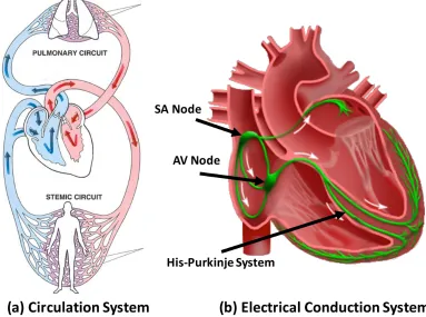
Figure 2.1: (a) The circulation system (http://revisionworld.com/). (b) Electrical Conduc-tion system of the heart
pumps low-oxygen blood to the lungs. The blood gets oxygenated in the lungs and gathers into the left ventricle. In the stemic circulation, the oxygenated blood in the left atrium is pumped into the left ventricle. The left ventricle pumps the blood to the rest of the body and the heart itself. After the body extracts the oxygen from the blood and injects carbon dioxide, the oxygen-depleted blood then flows back to the right atrium.
2.1.2
Electrical Conduction System of the Heart
Figure 2.2: (a) Lead placement for a dual chamber pacemaker. (b) Electrogram (EGM) signals measured from pacemaker leads and corresponding internal pacemaker events
muscle contractions to push blood into the ventricles. After a long conduction delay at the AV node so that both ventricles are fully filled, the signals conduct through fast-conducting His-Purkinje system to trigger almost simultaneous contractions of the ventricles and pump blood out of the ventricles.
Derangement from NSR can result in insufficient cardiac output and thus insuf-ficient oxygen supply to the body and/or the heart itself, which are referred to as Arrythmia. Arrhythmia impair the heart’s ability to efficiently pump blood and com-promise the patient’s health. Arrhythmia are categorized into so-called Tachycardia and Bradycardia. Tachycardia features undesirable fast heart rate which can cause inefficient blood pumping. Bradycardia features slow heart rate which results in in-sufficient blood supply. Bradycardia are due to failure of impulse generation with anomalies in the SA node, or failure of impulse propagation where the conduction from atria to the ventricles is delayed or blocked.
2.1.3
Electrophysiology and Implantable Cardiac Devices
The electrical activities of the heart closely couple with the mechanical contractions thus the electrical activities of the heart can be monitored and used to diagnose arrhythmia. The most well-known method is Electrocardiogram (ECG), which mea-sures the integration of electrical activities of the heart measured along different axis on the body surface. The electrical activities can also be directly measured by insert-ing electrodes through the vein into the heart. The electrodes are placed against the inside heart wall and localized electrical activities can be measured. Physicians can also deliver pacing sequence through the electrodes to explore the heart conditions. This procedure is referred to as Electrophysiological (EP) Testing (Josephson [2008]) and the signals are referred to as electrograms (EGMs) (Fig. 2.2.b). The timing and morphology of the ECG and EGM signals together are used to diagnose arrhythmia.
treat bradycardia. A typical dual chamber pacemaker has two leads inserted into the heart through the veins which can measure the local electrical activity of the right atrium and right ventricle respectively (Fig. 2.2.a). According to the timing between sensed impulses, the pacemaker may deliver electrical pacing to the corresponding chamber to maintain proper heart rhythm.
2.2
A Dual Chamber Pacemaker Specification
The focus of this section is implantable pacemaker, which is one of the simpler im-plantable cardiac devices. The specifications are based on the algorithm descriptions from Boston Scientific manuals (Boston Scientific Corporation [2007b]) and the func-tional description released as part of the Pacemaker Challenge (Boston Scientific Corporation [2007a]).
The pacemaker is designed for patients with bradycardia (i.e. slow heart rate). Two leads, one in the right atrium and one in the right ventricle, are inserted into the heart and fixed onto the inner wall of the heart. These two leads monitors the local activation of the atria and the ventricles, and generate corresponding sensed events (AS, VS) to its software. The software determines the heart condition by measuring time difference between events and delivers pacing events(AP, VP) to the analog circuit when necessary. The analog circuit then delivers pacing signals to the heart to maintain heart rate and A-V synchrony. In order to deal with different heart condition, pacemakers are able to operate in different modes. The modes are labeled using a three character system (e.g. xyz). The first position describes the pacing locations, the second location describes the sensing locations, and the third position describes how the pacemaker software responds to sensing. Here we introduce the widely used DDD mode pacemaker which is a dual chamber mode with sensing and pacing in both atrium and ventricle.
A DDD pacemaker has five basic timing cycles triggered by external and internal events, as shown in Fig. 2.3.
Lower Rate Interval (LRI)
The Lower Rate Interval (LRI) defines the longest interval allowed between two ven-tricular events, thus keeping the heart rate above a minimum value. In DDD mode, the LRI interval is divided into a V-A interval (TLRI-TAVI) and a A-V interval (TAVI). Since the last ventricular event (VS, VP), if no atrial event has been sensed
(AS), the pacemaker will deliver atrial pacing (AP) after TLRI-TAVI. (Marker 1 in Fig. 2.3)
Atrio-Ventricular Interval (AVI) and Upper Rate Interval (URI)
atrial event(AS, AP), and the time since the last ventricular event(VS, VP)is longer than TURI, the pacemaker will deliver ventricular pacing(VP). (Marker 3 in Fig. 2.3) The URI limits the ventricular pacing rate by enforcing a lower bound on the times between consecutive ventricle events.
2.2.1
Post Ventricular Atrial Refractory Period (PVARP)
and Post Ventricular Atrial Blanking (PVAB)
Ventricular events, especially Ventricular Pace(VP)are sometimes so strong that the atrial lead can sense the activation as well. This signal may be falsely recognized as an atrial event and disrupt normal pacemaker function. This scenario is called crosstalk and was discussed in our previous work (Jiang and Mangharam [2011]). In order to prevent this undesired behavior, and filter potential noises, there is a blanking period (PVAB) followed by a refractory period (PVARP) for the atrial events after each ventricular event (VS, VP). Atrial events during PVAB are ignored and atrial events during PVARP trigger AR! events which can be used in some advanced diagnostic algorithms. (Marker 2 in Fig. 2.3)
2.2.2
Ventricular Refractory Period (VRP)
The VRP follows each ventricular event (VP, VS) to filter noise and early events in the ventricular channel which could otherwise cause undesired pacemaker behavior.
1 2 3
Ventricular rate slower than physiological need
Ventricular rate faster than physiological need
Intrinsic Ventricular tachycardia
Pacemaker increases Ventricular rate
faster than physiological need
Endless loop Tachycardia Pacemaker fails to
increase ventricular rate above physiological need
Atrial Tachycardia
Response
Figure 2.4: Fault Tree Analysis (FTA) for two failures of a pacemaker
2.3
Identify Hazards in the Dual Chamber
Pace-maker Design
Implantable pacemakers are designed to treat bradycardia by increasing the heart rate with external pacing. Therefore the heart rate should not only be 1) increased to the minimum physiological need, but also 2) should not be increased beyond phys-iological need. Failing to satisfy the two requirements leads to failures that may be harmful to the patient. Fault tree analysis (FTA) is a top down and deductive failure analysis in which an undesired state of a system is analyzed using Boolean logic to combine a series of lower-level events. Fig. 2.4 demonstrates two FTAs for two failures corresponding to the two requirements. In this section we introduce two well-studied safety hazards in a basic dual chamber pacemaker design.
2.3.1
Endless-Loop Tachycardia
Intrinsic pathway
Fast “pathway”: pacemaker A-V synchrony
(a) Virtual circuit formed by the pacemaker and the heart
0 1000 2000 3000
AS AS AS AS AS
VS VP VP VP VP VP
ms AS
1 2
3
(b) Pacemaker trace for ELT initialized by a early ventricular signal
Figure 2.5: Endless Loop Tachycardia case study demonstrating the situation when the pacemaker drives the heart into an unsafe state (Jiang et al. [2011])
driving the ventricular rate as high as the Upper Rate Limit. During ELT, the heart rate is not only high, but also fixed without changing according to physiological need, which is an unsafe scenario.
2.3.2
Atrial Tachycardia Response
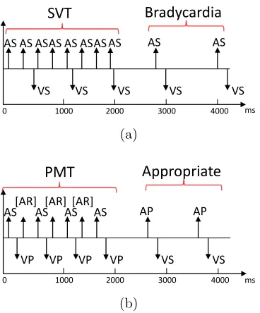
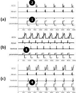
Supraventricular Tachycardia (SVT) is an arrhythmia with an abnormally fast atrial rate. Typically, in a heart without pacemaker, the AV node, which has a long re-fractory period, can filter most of the fast atrial activations during SVT, thus the ventricular rate remains relatively normal. Fig. 2.6(a) demonstrates a pacemaker event trace during SVT, with a pacemaker in ODO mode, which just sensing in both channels. As there is no pacing in ODO mode, the heart is in open-loop with the pacemaker. In this particular case, every 3 atrial events (AS) correspond to 1 ventric-ular event (VS) during SVT. As an arrhythmia, SVT is still considered a safe heart condition since the ventricles operate under normal rate and still maintain adequate cardiac output.
0 1000 2000 3000 4000
AS AS AS AS AS AS AS AS AS
VS VS VS VS VS
AS
ms
SVT Bradycardia
(a)
0 1000 2000 3000 4000
AS [AR] AS AS AS AP AP
VP VP VP VP VS VS [AR] [AR]
ms
PMT Appropriate
(b)
Figure 2.6: Benign open loop case: SVT without a pacemaker or with a pacemaker in sense-only mode (ODO) (b) Dangerous closed-loop-case SVT with DDD pacemaker which tries to match the fast atrial rate with a corresponding (and dangerous) fast ventricular rate.
2.4
Discussion
Implantable cardiac devices such as implantable pacemakers are typical autonomous medical devices. Despite their seemingly simple controllers, the pacemakers also subject to the three challenges discussed in Chapter 1:
• The physiology of the heart and its interaction with the rest of the body are complex.
• The pacemakers have to safely operate within a large variety of physiological conditions.
• A dual chamber pacemaker can only observe electrical activities from two local sites in the heart.
Chapter 3
Theme 1: Modeling the
Physiological Environment
The safety and efficacy of autonomous medical devices have to be evaluated within their physiological environment. Models of human physiology can replace real patients and enable closed-loop evaluation earlier during device development. In this chapter, a heart model structure is developed for closed-loop validation of implantable cardiac devices. This chapter aim to address the following questions:
• How much detail does the physiological model need?
• How to validate the physiological model?
• What applications can the physiological models be used?
3.1
Related Work
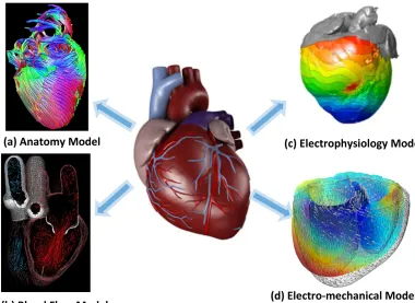
Figure 3.1: Physiological models of the heart from different perspectives
been modeled to synthesize optimal control of pacemaker pacing. (Bogdan et al. [2013]) Abstraction of the electrical cellular model has also been attempted by Islam et al. [2014] to reduce model complexity without sacrificing accuracy. The electrical properties and the mechanical properties of the heart are closely coupled. Models combining both of these aspects are also developed to study the effects of different arrhythmia on cardiac outputs (Trayanova and Boyle [2014], Rossi et al. [2011]).
3.2
EP Heart Model Structure for Closed-loop
Val-idation of Implant-able Cardiac Devices
Models should be designed in accordance with their respective applications. The aforementioned models of the heart are designed for understanding the mechanisms of different heart diseases. For closed-loop evaluation of autonomous medical devices, physiological modeling should have the following considerations:
C2. Differentiate different physiological conditions: To evaluate the safety and effectiveness of the device, the device has to be evaluated under certain phys-iological conditions specified by the requirements. For example, the pacemaker is supposed to maintain proper heart rate during Bradycardia. The model should be expressive enough to be able to differentiate the physiological condition (Bradycardia in the example) from other conditions. Failing to do so may result in false-positives or false-negatives in the evaluation result.
C3. Physiological/logical interpretation of model states: In closed-loop evaluation we are checking the device safety and effectiveness against the physiolog-ical requirements. However, due to the limited interface (e.g. two leads for a dual chamber pacemaker) it is always difficult to determine only from an execution trace that the therapy is safe and effective. Therefore, being able to provide physiological meanings to the states of the model also allows us to interpret the closed-loop execu-tion more accurately, thus reducing the number of physiologically invalid execuexecu-tions during the evaluation. To satisfy these requirements, the model structure of these physiological models should base on physiological or clinical first principles so that states and state transitions of the closed-loop executions can be explained with phys-iological language.
C4. Available patient data: In closed-loop evaluation, physiological models are developed to represent certain physiological condition across a population of patients or even particular patients. The model parameters must be identified so that the be-haviors of the models match the bebe-haviors of the patients (groups). Due to the limited sensing capability of closed-loop medical devices, the obtained data is sparse: i.e. we can not put a sensor on every tissue region of the heart. Therefore the complexity of the model should be in accordance with the available data to avoidover-fitting, which occurs when a model has too many parameters relative to the number of observations, and this can introduce errors during prediction.
The electrophysiological models mentioned in the last section (Trayanova and Boyle [2014], Grosu et al. [2011]) satisfy C1-C3. However, the parameter space of these models are too large (10+ parameters for each cellular model multiplied by 105 of elements) which not only increase simulation complexity, but also impossible to identify due to lack of data. As introduced in Section 2.1.3, the pacemaker has only two leads at fixed locations and only use timing between local activation events for diagnosis. These models with high spatial fidelity possess details that can be abstracted without sacrificing the model accuracy.
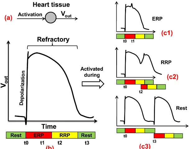
Figure 3.2: (a) The generation of Action potential; (b) Action potential; (c1) The second activation arrived during ERP; (c2) Arrived during RRP; (c3) Arrived after refractory.
diagnose most arrhythmia thus distinguish them (C2,C3), and 3) there are abundant patient data available (C4).
In the remaining chapter we will introduce the heart model structure based on EP testing, and model adaptation for two different applications of closed-loop evaluation of implantable cardiac devices.
3.2.1
Timing Behaviors of Cellular Electrophysiology
wave (Fig. 3.2(c2)). Fig. 3.2(c1)-(c3) show the action potential shape change and corresponding timing change in refractory periods when the tissue is activated at time stamp t1, t2,t3 after the initial activationt0.
3.2.2
Heart Model Components
We introduce the model components that can be used to configure heart models corresponding to different heart conditions. As discussed earlier, the action potential of a heart tissue has 3 timing periods during which the tissue responds to external electrical stimuli differently. We use an extended timed-automata formulation (Alur and Dill [1994]) to model the timing behaviors of a heart tissue during each cycle.
Node Automata: We refer to the tissue model asnode automatonand Fig. 3.3.(a) shows the structure of a node automaton i. 3 states correspond to the timing peri-ods of the action potential. From Rest state, the node can either self-activate or get activated by external stimuli (Act node) and go to ERP state. During ERP state the node does not respond to external stimuli (blocked). DuringRRPstate, the node can still be activated and go to ERP state, however the ERP period and the conduction delay of the tissue are affected by the ”earliness” of the activation arrived during the RRP period, which is tracked by a shared variable C(i). The new ERP period is determined by a function over clock value g(f(t)) which mimics the beat-to-beat dynamics described in Josephson [2008]. The function g and f are given by:
f(t) = 1−t/T rrp (3.1)
and
g(x) =
Tmin+ (1−(1−x)3)·(Tmax−Tmin), i=AV
Tmin+ (1−x3)·(Tmax−Tmin), i6=AV
(3.2)
where Tmin and Tmax are the minimum and maximum value for Terp of the tissue.
Due to the limited number of observable points within the heart, modeling the electrophysiological behavior of every tissue of the heart and its full anatomy is un-necessary and unfeasible. In our heart models, only self-activating tissue and key hubs of the electrical conduction system are modeled as node automata.
Path Automata: The electrical conduction through the tissue between nodes are abstracted using path automata. The path automata can be used to represent struc-tural or topological (functional) electrical connections between nodes. Fig. 3.3.(b) shows a path automaton connecting node a and b.
(a)
(b)
(d)
(c)
Figure 3.3: (a) Node automaton: The dotted transition is only valid for tissue (like SA node) that can be activated by an external trigger; (b) Path automaton modeling the electric conduction and propagation between two node automata; (c) Electrical conduction system of the heart; (d) Model of the electrical conduction system of the heart using a network of node & path automata ( Jiang et al. [2012a]).
This corresponds to the change of the conduction delay that is caused by the early activation. Similar to node automaton, the changing trend is extracted from clinical data and the function h is defined as:
h(c) =
path len/v·(1 + 3c), i=AV
path len/v·(1 + 3c2), i6=AV (3.3)
transition to Idle state. The intermediate state Conflict is designed to prevent back-flow, where the path is activated by the node b it has just activated. If during Ante or Retro state another Act path event is received from the other node connected to the path automaton, a transition to Double state will occur, corresponding to the two-way conduction. In this case, the activation signals eventually cancel each other and the transition to Idle state is taken.
3.2.3
Modeling the Heart’s Electrical Conduction System
The node and path automata are the basic building blocks for EP heart modeling. Hearts with different conditions are modeled by using different conduction topologies with appropriate timing parameters for each node and path automata. Fig. 3.3.(d) shows one such topology of a network of node and path automata.
3.3
Interaction with the Heart Model
In this section, we first introduce a probe model we developed to generate synthetic EGM signals from the EP heart model. We then use two case study to demonstrate that the probe model enables the EP heart model to evaluate device malfunctions due to sensing errors.
3.3.1
Probe Model for Synthetic EGM Generation
In EP testing and during pacemaker implantation, the local electrical activities, mea-sured as electrogram (EGM) signals, are used to diagnose heart conditions. During heart model construction, we can assign a node automaton at electrode locations and the transitions to the ERP state can be used to represent the local activation events. In a more general setup where electrodes are assigned anywhere within the heart model, a probe model is designed to generate synthetic EGM signals using spatio-temporal information from the proximity to the network of node and path automata.
Figure 3.4: The influence of conduction velocity and probe configuration on the EGM morphology. The left columns show the placement of probes in relation to the path; the right columns show the functional EGM.
probes can be placed anywhere within the heart model and generate clinically-relevant EGMs.
With the sensing model, the heart model structure can be used to identify safety hazards caused by sensing errors.
3.3.2
Pacemaker Oversensing and Crosstalk
(a)
(b)
(c)
1 2
3
4
Figure 3.5: Crosstalk between pacemaker leads with high sensitivity in the ventricle, ad-justed sensitivity and ventricular safety pacing
subsequent ventricular pacing (VP). This is indicated by no QRS-wave in the ECG channel. (Marker 2) For a patient with complete heart block this will cause dangerous ventricular asystole, meaning a long time without ventricular events.
Increasing the sensing threshold of the ventricular channel can prevent false sens-ing. In Fig. 3.5(b), the small signals in ventricular EGM are ignored and ventricular pacing are successfully delivered.
3.3.3
Lead Displacement
Lead displacement affects many patients and can result in inappropriate or ineffective therapy. Fig. 3.6. (b) shows the simulation result for the pacemaker function when the leads are in their designated location. From the figure we can observe: 1) Each P-wave is initialized by an Atrial Pace signal. 2) Each QRS complex is initiated by a ventricular pacing signal. 3) The interval between AP and VP is 150 ms, which matches the programed AVI period.
(a)
(b)
(c)
Figure 3.6: (a) Dotted line shows the location where the atrial lead should be (b) Pacemaker function before lead dislodge. (c) Pacemaker function after lead dislodge
the ventricle rather than atrium and atrial pacing will initiate a ventricular event. Fig. 3.6.(c) shows the simulated EGMs in this case. The figure reveals several facts: 1) No P wave is sensed or tracked (Marker 1). 2) Atrial Pace initiates an abnormal, wide QRS which is then sensed by the ventricle lead (Marker 2). 3) Intermittent ap-pearance of VP on QRS 110 ms after the AP. The ventricular lead can receive signal from: 1) pacing signal sent from the atrial lead, 2) the intrinsic A-V conduction path. The two paths are shown in Fig. 3.6.(a) and form a timing race condition. When the signal from the atrial lead arrives the ventricular lead first, it will trigger VS. If the intrinsic signal arrives the ventricular lead during the VSP sensing window (defined in previous section), it will trigger VSP. Although the pacing is ’safe’ because the pacing is early enough to avoid the vulnerable refractory period, the damage caused by pacing on depolarized tissue is currently a matter of much investigation.
3.4
Heart-on-a-Chip Platform
Heart Model Assembly
(Heart à Model) (Model HDL Generation à Code)
FPGA Synthesis (Code à Hardware)
Heart Model in Simulink à VHDL Code Genera6on à Synthesis for FPGA à Closed-‐loop tes6ng
Figure 3.7: The heart model was developed in Matlab/Simulink and code was automatically generated to operate on an FPGA platform for platform-level testing.
implemented on a lower cost fast micro-controller platform. The fast clock ensures that executions of all nodes and paths can be finished within 1ms. The Heart-on-a-Chip platform includes a heart model implementation which is able to represent common heart conditions such as bradycardia, tachycardia, heart block, etc (for mode details refer to Jiang et al. [2012a]). The parameters of the heart model can be changed at run-time by either switching among pre-defined parameter sets, or sending values directly to the model through a user interface in Matlab. A monitoring system observes logical interactions between heart model and the pacemaker and checks them against safety invariants at run-time.
![Figure 1.7: Validation activities during the software development life cycle (D A. Vogel[2011])](https://thumb-us.123doks.com/thumbv2/123dok_us/9331234.1467738/30.612.113.536.82.324/figure-validation-activities-software-development-life-cycle-vogel.webp)