http://www.sciencepublishinggroup.com/j/ejb doi: 10.11648/j.ejb.20190701.12
ISSN: 2329-1745 (Print); ISSN: 2329-1737 (Online)
Report
Verifying Faraday’s Magneto-optical Effect for Some
Materials
Pooja Daggar, Suram Singh Verma
Department of Physics, Sant Longowal Institute of Engineering and Technology, Sangrur, India
Email address:
To cite this article:
Pooja Daggar, Suram Singh Verma. Verifying Faraday’s Magneto-optical Effect for Some Materials. European Journal of Biophysics. Vol. 7, No. 1, 2019, pp. 8-14. doi: 10.11648/j.ejb.20190701.12
Received: June 8, 2019; Accepted: July 9, 2019; Published: July 18, 2019
Abstract:
Magneto-optic effect is a phenomenon in which an electromagnetic wave propagates through a medium and gets affected by the presence of a quasistatic magnetic field. Verdet constant describes the strength of Faraday Effect for a particular material. The objective of this work was to measure the Verdet constant for different transparent materials. The Verdet constant is measured by using the Faraday Effect which is a magneto-optical phenomenon; mean it describes the rotation of the plane of polarization of light with in a medium when it is placed in an external magnetic field. So this experiment determines the rotation of the plane of polarization with respect to the wavelength and the magnetic field. The experiment was carried out with different materials like flint glass, potassium iodide, potassium bromide, olive oil, glycerin, normal water and salty water. Reading observed through this experiment depicts a linear relationship between the angle of rotation and the magnetic field. The Verdet constant is determined to be at constant laser wavelength λ = 632.8nm. This effect was demonstrated in olive oil and water and value of Verdet constant be V=16.18 radian/T-m and 24.68 radian/T-m respectively and also show optical activity for glycerin. However, no change was noticed for black glass and salty water.Keywords: Magneto-optical Effect, Polarization, Magnetic Field, Verdet Constant
1. Introduction
The phenomenon of Faraday Effect was first discovered Michael Faraday in 1845. He discovered for the concrete evidence for the relation between the branch of Optics, magnetism and atomic Physics. He found out that when a block of glass is subjected to a strong magnetic field, it becomes optically active which we cannot observe with naked eyes. The effect occurs when a plane polarized light passes through a thickness of a transparent medium. This effect is not only limited to optically active materials, but also included some optically inactive materials placed in high magnetic fields. In magnetize medium, the refractive indices for right and left handed circularly polarized light are different. The effect in rotation of plane of polarization of linearly polarized light, this observable fact is called magneto-optic effect. The Faraday Effect is caused by left and right circularly polarized wave propagating at slightly at different speed, a property known as circular birefringence. It occurs as an internal
property of material when placed in external magnetic field. The direction of polarization, rotation depends on the properties of material through which the light is passed. This effect is widely used in optical isolators, phase modulators, spin dynamics, etc. Faraday rotation is also observed in astronomy and used to measure magnetic field in space. Faraday Effect is given by the relationship.
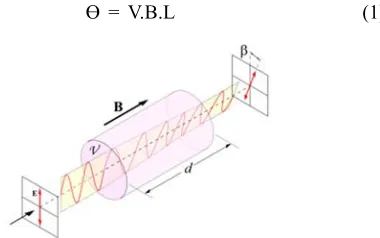
ϴ = V.B.L (1)
European Journal of Biophysics 2019; 7(1): 8-14 9
Where ϴ is the angle by which the plane of polarization of light rotates in radians, B is the uniform external magnetic field in Tesla, L is the length of sample material in meters, V is the Verdet constant. Verdet constant is characteristic of the medium and is defined as the rotation of the plane of polarization per unit magnetic field (Figure 1).
The linear light is seen to rotate in the Faraday effect can be seen as consisting of a right and left beam and the direction of the electric field rotates at the frequency of the other direction. The direction of rotation depends on the properties of the material through which the light is shown. A full treatment would have to take into account the effect of the external and radiation- caused fields on the wave function of the electrons, and then calculate the effect of this change on the refractive index of the material for, to see whether the right or left is slowed down more. The Faraday effect has been used to measure optical rotator power and for sensing of magnetic fields (such as fiber optic current sensors). The Faraday effect is used in spintronics research to study the polarization of electron spins in semiconductors. Faraday rotators can be used for amplitude modulation of light, and are basis of optical isolators and optical circulators; such components are required in optical telecommunications and other laser applications.
2. Experimental Setup
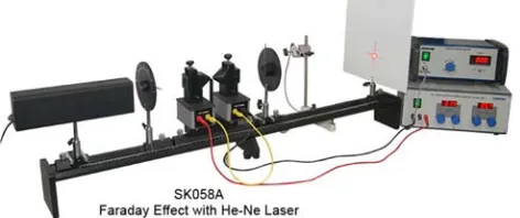
The experiment setup (figure 2) used to accurately measure the Verdet constant and this apparatus set was purchased from INDOSAW.
Figure 2. Experimental setup.
Apparatus parts:
a. He- Ne Laser
b.1 U-core c. 1 photometer
d.Digital Gauss Meter with hall probe e. 1 Rider base for electromagnet f. 1 Polarization filters
g.1 Analyzer filter
h.1 Sample material with holder i. 2 Coil with 300 turns
j. 1 Photometer
k.Power Supply 30V, 10 Amp for Electromagnet
l. 1 stand rod, 25cm m.1 stand base
n.1 Optical bench setup
o.1 Pair cables 100cm, red/black Test materials
For performing experiment with flint glass, one requires a very strong magnetic field to rotate the plane of polarization of light. However, for weak magnetic fields as were available in laboratory, another type of transparent material have been used. The materials used in present investigations are: Glycerin, Olive Oil, Water, Salty water and Potassium bromide (KBr).
3. Experimental Procedure
Optical Bench Setup:
a. Arrange the He-Ne laser on the optical bench. b.Position a polarizer close to the laser.
c. Place the U-core of the demountable transformer with the two coils on the rider base with thread and fix it with the holder for the transparent sheet square.
d.Place the bored pole pieces on the U core in such a manner that the transparent sheet can be placed on the holder.
e. Use the clamps to fix the bored pole pieces on U-core. f. Position the analyzer close to U core on bench. g.Position the photometer opposite to the analyzer. h.Separate angular scale with the degree divisions which is
attached to the translucent screen photometer. All analyzer settings can be read off from this angular scale easily.
Electrical setup:
a. Connect the coils in series to the variable.
b.Connect the Laser to mains 230V AC supply.
c. The maximum coils current under permanent use is 6amp, however the current can be increased up to 8 to 10Amp for few minutes without the risk of damaging the coils by overheating.
Optical Adjustment:
a. Switch on laser and form an image of analyzer cross wire on the photometer.
b.Align the light source and the bored pole pieces in such a manner that maximum light passes through the bores in pole pieces (with no transparent sheet).
c. To project an image of thread cross on the analyzer onto the photometer, shift the lens toward the analyzer until a sharp image is observed.
Calibration of the magnetic field:
a. Remove the sample.
b.Connect the digital gauss meter to main switch. c. Place the hall probe between the pole pieces.
d.Use the standard material to hold the magnetic probe between the bored pole pieces.
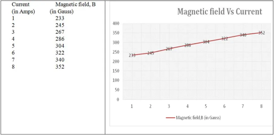
Figure 3. Current along x-axis (in ampere) Vs Magnetic field along y-axis (in gauss).
It shows that current is directly proportional to magnetic field. Due to the limitation of setup in the lab, the maximum coils current under permanent use is 6amp, however current can be increased up to 8 to 10amp for a few minutes without risk of damage to the coils by over-heating. Since electromagnets are used to generate the magnetic field for the experiment, a correlation between the current supplied to the electromagnets and the measured magnetic field in the space between the poles needed to be deduced. The magnetic field at the center of the poles was measured at each integer current between 1 and 8A.
Rotation of the polarization plane as a function of the magnetic field B
a. Switch ON He-Ne laser.
b.Align the sample between the bored pole pieces.
c. Set the desired magnetic field by means of the magnet current.
d. Set the analyzer to 0ᵒ position.
e. Find the minimum intensity by turning the polarizer. f. For a final minimum adjustment (almost dark) the
minimum light intensity can be easily checked by looking directly into the screen. The polarizer and the analyzer are set to the intensity minimum as it can be easier accessed then the intensity maximum.
g.Note the values of intensity at different angle by rotating the analyzer.
h.Note the value of intensity by using photometer or photodiode.
i. Repeat these steps for various magnetic fields by varying the magnetic current.
4. Results and Discussion
4.1. Olive Oil (Sample Thickness =1.5cm)
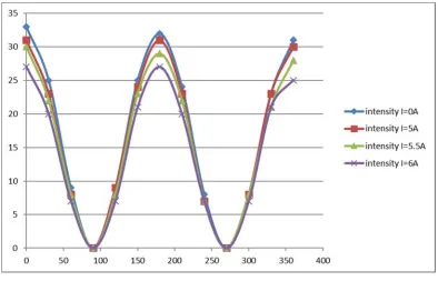
Table 1. Angle and intensity at different values for current (Malus’s law).
Angle (in degree ɸ) Intensity at (I=0Amp) Intensity at (I=5Amp) Intensity at (I=5.5Amp) Intensity at (I=6Amp)
0 33 31 30 27
30 25 23 22 20
60 9 8 8 7
90 0 0 0 0
120 9 9 8 7
150 25 24 23 21
180 32 31 29 27
210 24 23 22 20
240 8 7 7 7
270 0 0 0 0
300 8 8 8 7
330 23 23 21 21
European Journal of Biophysics 2019; 7(1): 8-14 11
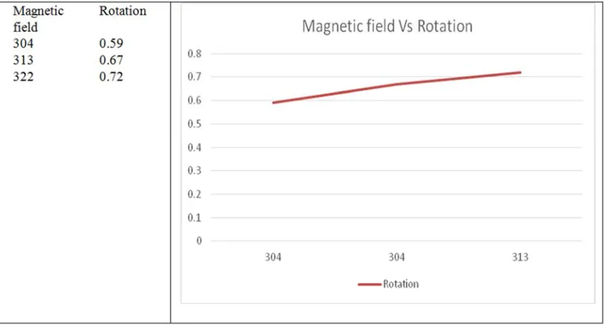
Magnetic field and angle of rotation for constant wavelength = 632.8nm
Figure 4. Graphical representation for Olive oil by Malus’s Law. Rotation angle along x-axis (in degree) and Intensity along y-axis for different value of current.
Figure 5. Graph between magnetic field (in gauss) along x-axis and rotation angle (in degree) along y-axis.
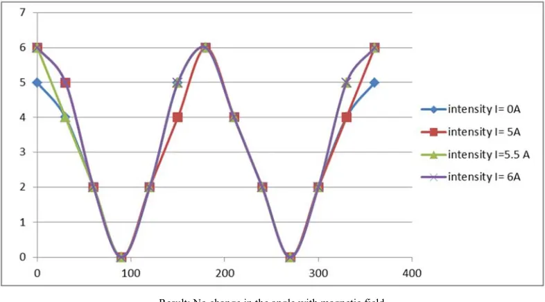
4.2. Black Glass (Sample Thickness=6mm)
Table 2. Angle and intensity at different values for current (Malus’s law).
Angle (in degree ɸ) Intensity at (I=0Amp) Intensity at (I=5Amp) Intensity at (I=5.5Amp) Intensity at (I=6Amp)
0 5 6 6 6
30 4 5 4 5
60 2 2 2 2
90 0 0 0 0
120 2 2 2 2
150 5 4 5 5
180 6 6 6 6
210 4 4 4 4
240 2 2 2 2
270 0 0 0 0
300 2 2 2 2
330 4 4 5 5
Result: No change in the angle with magnetic field.
Figure 6. Graph representation for black glass by malus law. Giving rotation angle along x-axis and Intensity along y-axis for different values of current.
4.3. Water (Sample Thickness=1.5cm)
Table 3. Angle and intensity for different values of current (Malus’s law).
Angle (in degree ɸ) Intensity at (I=0Amp) Intensity at (I=5Amp) Intensity at (I=5.5Amp) Intensity at (I=6Amp)
0 41 34 32 30
30 31 27 25 24
60 11 10 9 9
90 0 0 0 0
120 11 9 9 8
150 31 26 24 22
180 40 32 29 28
210 30 25 25 24
240 9 9 8 8
270 0 0 0 0
300 8 9 9 9
330 25 25 25 25
360 34 32 32 30
Magnetic field and angle of rotation for constant wavelength = 632.8nm
European Journal of Biophysics 2019; 7(1): 8-14 13
Figure 8. Graph between magnetic field (along x-axis) and angle of rotation (along y-axis).
4.4. Glycerin (Sample Thickness=1.5cm)
Table 4. Angle and intensity at different values of current (Malus, s law).
Angle (in degree ɸ)
Intensity at (I=0Amp)
Intensity at (I=5Amp)
Intensity at (I=5.5Amp)
0 27 29 30
30 21 22 24
60 8 8 8
90 0 0 0
120 7 8 8
150 21 23 24
180 27 30 32
210 22 23 25
240 7 8 8
270 0 0 0
300 8 8 8
330 22 22 25
360 29 30 32
Result: Rotation of angle with magnetic field in anti-clockwise direction.
Figure 9. Graph between rotation angle (x-axis) and intensity (y-axis) at different values of current for glycerine.
4.5. Salty Water (40% Concentration) (Sample Thickness=1.5cm)
Table 5. Angle and intensity at different values of current (Malus’s law).
Angle (in degree ɸ)
Intensity at (I=0Amp)
Intensity at (I=5Amp)
Intensity at (I=5.5 Amp)
Intensity at (I=6 Amp)
0 4 4 4 4
30 3 3 3 3
60 1 1 1 1
90 0 0 0 0
120 1 1 1 1
150 3 3 3 3
180 4 4 4 4
210 3 3 3 3
240 1 1 1 1
270 0 0 0 0
300 1 1 1 1
330 3 3 3 3
360 4 4 4 4
5. Results
Verdet constant for:
1.Olive oil is found as 16.18rad/T-m and 0.00093 degree/G. cm.
2.Water is found as 24.66rad/T. m and 0.0014 degree/G. cm.
3.No rotation was noticed in case of black glass and salty water (may be due to low magnetic fields available). 4.A negative rotation was noticed in case of Glycerin. 5.Similar problems were faced with pallets made up of
Potassium Bromide (KBr) and Potassium Iodide (KI).
6. Conclusion
The effect of rotation of plane polarized light is used every day especially by organic chemists who use the optical properties of chiral compounds for identification purposes. But less used in the magnetically induced optical activity seen in Faraday effects. The application of magnetic field causes the medium to become optically active and as magnetic field increased the angle of rotation increased. The project successfully measures the Verdet constant for different materials. There is a significant rotation in plane of polarization especially in shorter wavelengths. This effect was demonstrated in olive oil and water and value of Verdet constant be V=16.18 radian/T-m and 24.68 radian/T-m respectively and also show optical activity for glycerin. However, no change was noticed for black glass and salty water. From our result we found that the Verdet constant for olive oil and water is positive and negative for Glycerin. The rotation of water and olive oil is clockwise looking parallel to magnetic field for both direction of propagation. We found that Verdet constant of water at 632 nm is greater than the olive oil.
References
[1] Kales M. L., Modes in wave Guides containing Ferrites, Journal of Applied physics 24 (5) (2008) 604.
[2] Larry W., Charles H., (ed), The ARRL handbook for radio Amateurs sixty eighth edition, America radio relay league (1990).
[3] Stefaan G, Vandendriessche, Faraday rotation in Mesogenic organic molecules. Chemistry of materials (2013) 1139. [4] Shakir A. A, Mudhafa-AL. R. D., Dergazly-AL. A. A., Verdet
constant measure -ement of olive oil for magnetic field sensor, International Journal of Advances in Electrical and Electronics Engineering (2004) 2319.
[5] Ehsan T., mohammad T., Verdet constant measurement of nanocrystal and thin film of cadmium maganease telluride, Optik (2015) 3919.
[6] Thomas G. S., Verdet constant of light flint glass, Physics Department, The college of Weester (2003).
[7] Stites R. W., O’Hara K. M, The Verdet constant of undoped Y3Al5O12 in the near infrared, Optics Communication 285 (2013) 3997.
[8] Toporov A. Y. U., Nikitin P. I. M. V. V., Beloglazow A. A., Perrone A. A. L., Faraday effect in thin amorphous magnetic films, Sensors and Actuators A, 59 (1997) 326.
[9] Willet C. S., An Intoduction to Gas Lasers, Pergamon Press, (1974) 411.
[10] White A. D., Rigden J. D., Continuous Gas Laser operation in the visible, Proc IRE vol. 50 (1962) 1697.
[11] Gasvik K. J., Optical Metrology (3rd ed.). John wiley and Sons. ISBN 0470846704 (2003) 219.
[12] Draper J. W., A textbook on chemistry. NY: Harper and Brothers (1861) 78.
[13] Indosaw apparatus
(http://universeits-pilani.ac.in/uploads/manjuladevi/magnetopt ic Effect.pdf).
[14] Belapura J. S., Faraday rotation effect, M.Sc.-I Report, University of Pune, India (2007).