HARDWARE IMPLEMENTATION OF
THE PCM CODEC FOR VOIP
TELEPHONY
LUCIEN NGALAMOU
School of Engineering, Grand Valley State University 301 W. Fulton Street, Grand Rapids, MI 49508, USA
MARCUS GEORGE
Dept. of Electrical and Computer Engineering, University of the West Indies St. Augustine, Trinidad and Tobago
LEARY MYERS
Department of Physics and Engineering, University of the West Indies Mona Campus, Kingston 7, Jamaica
Abstract:
This paper presents the hardware implementation of the pulse code modulation coder and decoder (PCM Codec), that aims at improving the delay of the speech compression of this codec, which is originally implemented in software for Voice-over Internet Protocol (VoIP) Telephony. This design provides a solution known as intellectual property (IP) core ready to be deployed in a reconfigurable architecture with other voice codecs. Such architecture can then be used to improve the Quality-of-Service (QoS) of VoIP Telephony.
Keywords: PCM; Delay; Hardware Implementation; IP Core; VoIP Telephony.
1. Introduction
The quality of service refers to a measure or guarantee of performance. It is generally accepted that IP data networks are “best effort” networks and therefore transmitted data is not guaranteed to arrive at its destination. Also the time for different packets to arrive is variable. For conventional data, this is not a problem since the delay involved is not important and protocols such as TCP can be used in order to ensure that all data is properly received. But for real-time services such as VoIP, these events will affect system performance.
Quality-of-Service (QoS) factors [Ribadeneira (2007)] which are typically measured for VoIP traffic include delay, jitter and packet loss. Delay is defined as the length of time required to move a packet/signal from source to destination. Jitter is defined as the variation in the sequence of packets received on the receiver side relative to the sequence of packets sent from the sender side. Packet loss is defined as the percentage of packets transmitted from the sender which are not delivered to the receiver. Jitter and packet loss depend entirely on the status of the network. Delay however has some dependence on components of the IP network.
Figure 2 [Arora (1999)] illustrates various types of delays existing on a VoIP network. Algorithmic delay is introduced by the speech compression algorithm and is dependent on the coding algorithm. Packetization delay is the time over which samples are accumulated before they are packeted. Serialization delay is the time required to initially transmit the IP packet and also includes delays incurred whenever a packet passes through a store-and-forward device (such as a router or a switch).
Propagation delay is the time required for the electrical or optical signal to travel along a transmission medium and is a function of the geographic distance. Component delay is caused by the various components within the transmission system. For example, a segment passing through a router has to move from the input port to the output port through the backplane. The focus of this work is on quantifying and potentially reducing algorithmic delay. Processing delay is the time required to process the header of a packet received from the IP network after transmission. Finally, playback buffer delay is the time required to reproduce speech samples from received packets.
Figure 2: Various delays associated with a VoIP system [Arora (1999)]
1.1. Speech Compression
A speech signal is a sound formed by humans in order to communicate. Like all other sound, it is a perturbation of the atmospheric pressure that travels in the form of a sound wave [Juan (1995)]. To transport speech over communication networks, the speech signal must be transformed from a sound wave to an electrical signal. This is usually done with a microphone and the result is an electrical signal where the voltage varies with the pressure of the speech signal.
vocal chords allow the passage of air into the vocal tract. They can be either opened or closed. When closed (voiced signals) they create a periodic oscillation with a fundamental frequency, known as the pitch. On the other hand when open (unvoiced signals) the pressure signal is not modulated.
1.2. Pulse Code Modulation (PCM)
The PCM algorithm is a waveform based speech compression algorithm. The international standard for PCM is ITU-T G.711 [ITU (1972)]. The G.711 algorithm PCM uses logarithmic scalar quantization and represents each speech sample with 8 bits. Logarithmic scalar quantization places most of the quantization steps at lower amplitudes by using the non-linear function logarithm function. The PCM algorithm converts speech in 16-bit uniform PCM format to 8-bit μ-law or A-law PCM format.
The μ-law/A-law PCM byte comprises of three components: sign bit, segment and interval. The sign of the input PCM sample is represented by bit 7 (MSB) of the uniform PCM byte, the segment to which the input PCM sample belongs to is represented by bits 4 to 6, and the position within the segment that the input PCM sample resides, known as the interval value is represented by the lower nibble. PCM is widely used due to its simplicity. This results in low algorithmic delay and high decoded speech quality but also a relatively high bit rate.
1.3. Objectives and Paper organization
The aim of the work presented in this paper is to demonstrate that PCM speech compression algorithm can be implemented in hardware with lower algorithmic delay than software implementations. To achieve this aim the following objectives were pursued:
a) Determine the latency (algorithmic delay) of software-implemented PCM speech compression algorithm. b) Produce hardware implementations of the PCM speech compression algorithm.
c) Determine the latency for the hardware-implemented PCM speech compression algorithms.
d) Compare the latency of both hardware and software implementations of the PCM speech compression algorithm.
The remainder of the paper is organized in three sections. Section 2 presents the profiling of the PCM’s software implementation, section 3 deals with the IP core design of the PCM, and section 4 concludes the paper.
2. Profiling the Software Implementation of PCM
Profilers are tools which monitor the time each instruction takes to execute in a given program and hence the total time needed for execution, i.e. the frequency with which functions call other functions. Profiling on Linux operating systems can be performed by compiling code with the GNU compiler so that profiling data is recorded during execution [Fenlason (1992)]. GProf [Gprof (2010)] is then run to analyze the profiled data.
Execution times displayed in the flat profile are estimates because they include overhead from other tasks running on the operation system. The execution time in nanoseconds displayed in the flat profile can be converted to machine cycles e.g. A desktop computer with 2.4GHz Intel(R) Pentium Duo Core E2220 processor is capable of executing at a clock speed of 2.4×10⁹ cycles per second. The processor speed specified corresponds to the speed at
which the processor operates. A dual core processor with a clock speed of 2.4GHz has two processors, each operating with a clock speed of 2.4GHz. An execution time can be converted to cycles by computing the product of the execution time in seconds and the number of cycles executed per second on the processor eg. 27ns = (27×10-6) ×
(2.4×109) = 64.8 cycles.
Gprof gives execution times in seconds, with a resolution of 0.1 second. Therefore, to determine the time required toexecute a short routine, the routine must be invoked by a program multiple times, after which the average execution time can be computed.
Sun Microsystems
Name of function end-to-end execution
time / ns cycles
PCM Encoder 33 (33×10-6) × (2.4×109) = 79200
PCM Decoder 36 (36×10-6) × (2.4×109) = 86400
Table 1: Latency of software implemented PCM speech compression algorithm from Sun Microsystems
3. Hardware Implementation of the PCM Codec
3.1. PCM Speech Compression Algorithm
The PCM encoder converts data in 16-bit two’s complement format to 8-bit μ-law/A-law PCM format using logarithmic scalar quantization. The PCM decoder converts the μ-law/A-law PCM byte received to 16-bit two’s complement format. The μ-law/A-law PCM byte (Figure 3) comprises of three components: sign bit, segment and interval. The sign of the input sample is represented by bit 7 (MSB) of the μ-law/A-law PCM byte, the segment to which the input sample belongs to is represented by bits 4 to 6, and the position within the segment that the input sample resides, known as the interval value is represented by the lower nibble.
Figure 3: Structure of a μ-law/A-law PCM byte
3.2. PCM Encoder Design
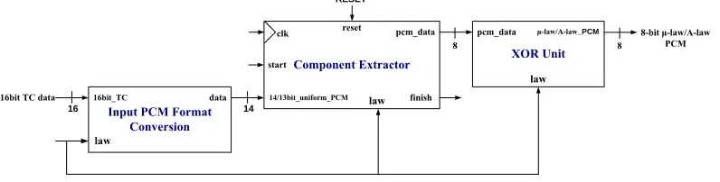
The PCM encoder (Figure 4) converts data in 14/13-bit uniform PCM format to 8-bit μ-law/A-law PCM format, and consists of three units. The input PCM format conversion unit converts speech in 16-bit two’s complement format to 14-bit two’s complement format (14-bit uniform PCM). The component extractor unit along with the XOR operation convert data in 14-bit two’s complement format to 8-bit μ-law/A-law PCM format. Among these three units, only the operation of the component extractor must be initiated and controlled. However a controller unit was not included because the latency of the input PCM format conversion and XOR units were very short and their operation does not need to be initiated or controlled. It can therefore be concluded that the exclusion of a controller unit would not have adversely affected the operation of the PCM encoder.
Component Extractor
start
pcm_data
finish clk reset
RESET
8
XOR Unit
law
μ-law/A-law_PCM
8
8-bit μ-law/A-law PCM
14
Input PCM Format Conversion
data
law
16
16bit_TC law
16bit TC data 14/13bit_uniform_PCM
pcm_data
Figure 4: Datapath block diagram of the PCM Encoder
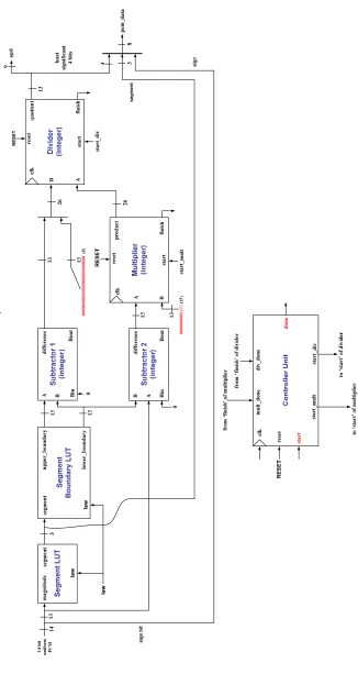
component extractor responsible for the computation of the interval was designed by applying the hardware design technique outlined in Equation 1.
2
1111
_
_
_
_
/
_
int
boundary
lower
boundary
upper
boundary
lower
law
A
law
erval
Equation 1: Interval computation for μ-law/A-law Component Extraction process
An integer multiplier and divider were used instead of floating point units in the computation of the interval because the quantized version of the interval has to be stored in the lower nibble of the μ-law/A-law PCM byte. The integer multiplier was placed before the divider to ensure that output values less than 1 are not obtained, thereby eliminating the need for floating point units to ensure correct computation of the interval. Another reason for choosing integer units is that they require less hardware than floating point units.
3.3. PCM Decoder Design
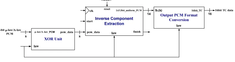
The PCM decoder, consists of three units, (Figure 6) and converts speech in 8-bit μ-law/A-law PCM format to 16-bit uniform PCM format. . The units are: theinverse-component extractor unit along with the XOR operation convert the μ-law/A-law PCM byte to 14-bit two’s complement format, and theoutput PCM format conversion unit converts speech in 14-bit two’s complement format to 16-bit two’s complement format. A controller unit was not included for the same reason given for its exclusion in the PCM encoder.
Figure 6: Datapath block diagram of the PCM Decoder
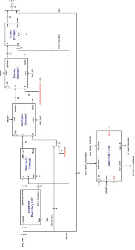
The inverse-component extractor (Figure 7) first extracts the sign bit (MSB) installed it as the sign bit of the 14-bit two’s complement sample. The segment and interval were used in computation of the least significant 13-bit of the two’s complement output. This section was designed by applying the hardware design technique outlined in Equation 2.
boundary
lower
boundary
upper
B
boundary
lower
A
B
value
erval
A
law
A
law
_
_
_
]
)
10000
(
_
int
[
_
/
_
2
Equation 2: μ-law/A-law value computation in the μ-law/A-law Computation process
Se g m e n t Boundary LUT S ubtract o r (i nteger) M u lti p li er (i nteger) Divi der (int eger) seg m en t up per _bo unda ry low er_ bou nda ry A B di ffe renc e Bi n Bou t A B sta rt star t pr odu ct qu ot ie n t fin ish fini sh clk clk res et rese t 3 0 RE SE T 13 13 RE SET 26 star t_d iv A B st ar t_ m u lt si gn bi t 8 in ter val _val ue 13 26 Ad d e r (i nteger) 13 A B 13 su m 0 Co ut Ci n low er _bou nda ry si gn 14 13 4 13 law 00 0000 000 (0) 9 13 00 0000 0000 0000 0000 0000 1111 (15 ) Co ntr o ll er U n it sta rt_ m u lt m ult_d one cl k rese t div_ don e st art_ div to ‘ sta rt’ o f d iv id er to ‘ sta rt’ o f m u lt ip lie r RE SET sta rt done fr om ‘f in is h ’ of d ivi d er from ‘f inish ’ of m ultipl ier pc m _d ata 14 -b it uni fo rm PC M la w
Figure 7: Datapath block diagram of the Inverse Component Extraction unit
3.4. Hardware Implementation of the PCM Speech Compression Algorithm
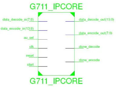
Figure 8. Interface View of the G7.11 Codec generated as a RTL Module
After implementing the PCM speech compression algorithms, they were synthesized in the Xilinx 11.1 ISE environment in preparation for verification and validation (figure 9).
Device Utilization Summary (estimated values) [-]
Logic Utilization Used Available Utilization
Number of Slices 4515 7680 58%
Number of Slice Flip Flops 7126 15360 46%
Number of 4 input LUTs 4737 15360 30%
Number of bonded IOBs 50 173 28%
Number of MULT18X18s 16 24 66%
Number of GCLKs 8 8 100%
Figure 9: Details of the resource utilization for the PCM Hardware Implementation. The timing summary is given below.
Timing Summary: --- Speed Grade: -5
Minimum period: 29.005ns (Maximum Frequency: 34.477MHz) Minimum input arrival time before clock: 23.434ns
3.5. Verification of the hardware implemented PCM speech compression algorithm
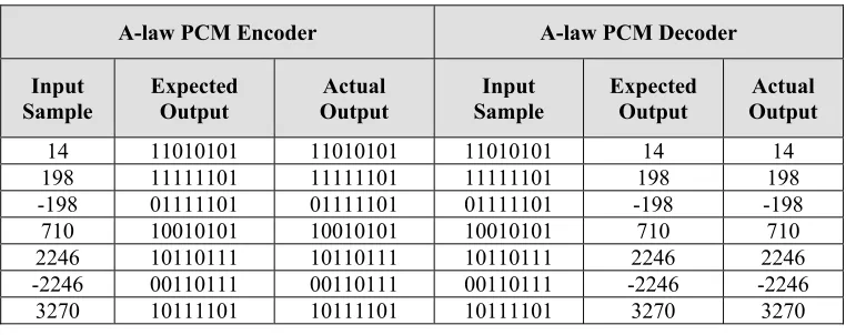
Test cases for the verification tests consisted of input samples belonging to each of the following categories: small, intermediate and large values along withpositive and negative values. The expected outputs for the PCM encoder were obtained from [ITU (1972)]. The actual outputs of the hardware-implemented PCM encoder were obtained through simulation using Modelsim XE 6.4b using the chosen test cases. The actual outputs were compared with the expected outputs to verify that the hardware-implemented PCM encoder correctly compressed the input test sequences.
The expected outputs of the implemented PCM encoder were used as the inputs to the hardware-implemented PCM decoder. The expected outputs for the PCM decoder were obtained from [ITU (1972)]. The actual outputs of the hardware-implemented PCM decoder were obtained through simulation using Modelsim XE 6.4b. The actual outputs of the hardware-implemented PCM decoder were compared to the input samples to the hardware-implemented PCM encoder to verify that the hardware-implemented PCM decoder correctly decompressed selected inputs.
The verification test results (Table 2 and Table 3) indicate that the actual outputs of the PCM encoder and decoder in μ-law and A-law modes corresponded to the expected outputs from [ITU (1972)]. This demonstrated that hardware-implemented PCM encoder and decoder correctly compressed and decompressed the input samples respectively.
u-law PCM Encoder u-law PCM Decoder
Input Sample
Expected Output
Actual Output
Input Sample
Expected Output
Actual Output
14 11111111 11111111 11111111 14 14
198 11010111 11010111 11010111 198 198
-198 01010111 01010111 01010111 -198 -198
710 10111111 10111111 10111111 710 710
2246 10011111 10011111 10011111 2246 2246 -2246 00011111 00011111 00011111 -2246 -2246 4294 10001110 10001110 10001110 4294 4294 7923 10000000 10000000 10000000 7923 7923
Table 2: Verification tests results for PCM Encoder and Decoder in u-law mode
A-law PCM Encoder A-law PCM Decoder
Input
Sample Expected Output Output Actual Sample Input Expected Output Output Actual
14 11010101 11010101 11010101 14 14
198 11111101 11111101 11111101 198 198 -198 01111101 01111101 01111101 -198 -198 710 10010101 10010101 10010101 710 710 2246 10110111 10110111 10110111 2246 2246 -2246 00110111 00110111 00110111 -2246 -2246 3270 10111101 10111101 10111101 3270 3270
Table 3: Verification tests results for PCM Encoder and Decoder in A-law mode
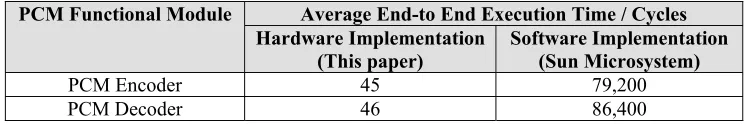
3.6. Validation of the hardware implemented PCM speech compression algorithm
encoder was 1760 times shorter than the latency of software PCM encoder, while the latency of the hardware PCM decoder was 1878 times shorter than the latency of the software PCM decoder.
PCM Functional Module Average End-to End Execution Time / Cycles Hardware Implementation
(This paper) Software Implementation (Sun Microsystem)
PCM Encoder 45 79,200
PCM Decoder 46 86,400
Table 4: Performance Comparison of Hardware and Software Implementations of PCM
4. Conclusion
The results presented in this paper clearly show that the actual outputs of the PCM encoder and decoder in both μ-law and A-law modes correspond to the expected outputs from (ITU 1972). This is a clear demonstration that hardware-implemented PCM encoder and decoder can correctly compress and decompress their input samples respectively and hence can be considered equivalent implementations of the PCM encoder and decoder. The validation results indicates that the latency (algorithmic delay) of both the hardware-implemented PCM encoder and decoder in both μ-law and A-law modes were 1760 and 1878 times shorter than the latency of their software counter-parts from Sun Microsystem respectively. This indicates that the algorithmic delay of the PCM speech compression algorithm which has been implemented in software can be significantly reduced by implementation in hardware.
Success in analyzing and implementing these speech compression algorithms in hardware was achieved As the PCM encoder and decoder correctly compresses and decompresses their input sequences respectively.
The main advantage of using hardware is speed as these algorithms use a great deal of processing power for computation. Software has the disadvantage of being slower but however has the benefit of flexibility. This implementation is customized to be used as an IP core in a upcoming project relating the application the application of reconfigurable architectures for efficient voice and video deployment over internet protocol.
References
[1] Arora, Rakesh. 1999. Voice over IP: Protocols and Standards. June 23. http://www.cs.wustl.edu/~jain/cis788-99/ftp/voip_protocols.pdf
(accessed April 04 2008)
[2] Bishop, David. 2008. Parameterized Fixed-Point Package. February 27. http://www.vhdl.org/fphdl/vhdl.html (accessed July 17 2009) [3] Grof, Gprof Profiler, http://sourceware.org/binutils/docs/gprof/index.html (accessed October 9, 2010)
[4] Halsall, Fred. 1998. Data Communications, Computer Networks and Open Systems. 4th. ed. Wales: Addison-Wesley Publishing Company.
[5] International Telecommunication Union (ITU). 1972. Pulse Code Modulation (PCM) of Voice Frequencies. G.711. [6] Juan, G. R. 1995. Introduction to the Physics and Psycholophysics of Music. 3rd ed. New York: Springer Verlag.
[7] Montminy, Christian. 2000. A Study of Speech Compression Algorithms for Voice Over IP. Msc Thesis. Ottawa-Carleton Institute for Electrical and Computer Engineering, University of Ottawa, Canada.
[8] Perry, Douglas. 1998. VHDL. 3rd ed. New York: McGraw-Hill.
![Figure 1: Components of VoIP Network [Montminy (2000)]](https://thumb-us.123doks.com/thumbv2/123dok_us/9614380.1489700/1.612.119.496.551.690/figure-components-voip-network-montminy.webp)
![Figure 2: Various delays associated with a VoIP system [Arora (1999)]](https://thumb-us.123doks.com/thumbv2/123dok_us/9614380.1489700/2.612.130.487.368.536/figure-various-delays-associated-voip-arora.webp)