ISSN: 2393-8366
Microcontroller Based Li-Ion Cell Balancing using
Single Switched Capacitor for Spacecraft Application
Sukanya P M1, Lincy P Benny2,Maneesha K M3, Reshma Unnikrishnan4, Thanseeha Kassim5
1
UG Scholar,Department of Electronics and Communication , Jyothi Engineering College,kerala,India
[email protected],[email protected],[email protected],
[email protected],[email protected]
Abstract: The emerging plugin hybrid vehicle technology requires larger battery packs which do not
compromise on its lifetime and performance and battery weight. Due to the manufacturing defects and performance variations of each individual cell in the pack, charge balancing is necessary In this paper we simulated and plotted using MATLAB/Simulink software. This paper aimed at proposing a microcontroller based Li ion cell balancing using single switched capacitor (SSC). SSC technique provides an efficient control over other techniques. This method help to reduce the thermal power consumption and power loss as compared with the passive topologies. It also provides higher efficiency and accuracy. This paper also includes a review and comparisons between the double tiered and single switched capacitor balancing topologies for battery string based on MATLAB/Simulink simulation. The comparison carried out according to circuit design, balancing simulation, practical implementations, application, balancing speed, complexity, cost, size, balancing system efficiency, voltage/current stress etc.
Keywords: Li-ion cells, Cell balancing, microcontroller, Single Switched Capacitor(SSC), MATLAB
simulation, charge transfer algorithm.
1. Introduction
ISSN: 2393-8366
results in series health hazards. This limits its application to short duration missions. Nickel-cadmium [2] batteries came in to seen in this scenario. But extra size and mass limited its use. The cadmium present in this battery is also harmful . It causes big health and environmental hazards. Then the introduction of Nickel-hydrogen batteries which is having the capacity of longer and more efficient life time than Ni-Cd batteries were reduced the impact of toxic metals. But it results in a new risk of flame and explosion hazard. Presently most of the spacecrafts are using Li-ion battery technology, due to its high voltage per cell, high volume density, and low self-discharge[3]. Moreover these batteries can provide power to the satellite very effectively during eclipse. Multiple cell configuration for Li–Ion batteries can be connected either in series or in parallel combinations of cells. This combination satisfies all the necessary conditions for satellite applications. Due to manufacturing tolerances internal resistance of each cell may vary. Thus the voltage in some cell can be over charged or undercharged, so that the capacity of the cells are reduced and the life of whole battery pack is decreased. Individual cell failures may lead to the replacement of entire battery pack and the consequences are extremely costly. Therefore a voltage balancing circuit is required for voltage equalization. The need for balancing is less for parallel chain, since the parallel connection holds all the cells at the same voltage and at the same time allows charge to move between the cells, i.e. they are self-balanced. Lead acid and Ni-MH cells can withstand a level of over voltage without sustaining permanent damage. A degree of cell balancing or charge equalization can occur with these technologies by prolonging the charging time, since the fully charged cells will release energy by gassing until the weaker cell reach their full charge. This is not possible with lithium cells which can’t tolerate over voltages.
2. Cell Balancing
2.1 What is Cell balancing
The performance of a battery stack with different single-cell capacities can significantly be increased when the charge from the cells is equalized with an electronic circuit [4], [5]. This is called cell balancing. Cell balancing refers to the technique that maximizes the capacity of a battery with multiple cells in series to make all of its energy available for use and increase the battery life. This is done by transferring energy from or to individual cells until the SOC (State Of Charge) of the cell with the lowest capacity is equal to the battery’s SOC. By this process of equalizing the cell voltage which makes all the cells remain within the operating range, the cells are balanced such that the overall battery voltage can be used to ensure that none of the cells are over-charged or over-discharged.
2.2 Why Cell balancing
ISSN: 2393-8366
manufacturing process due to technical and economical limitations. Hence, the cell capacities are initially not equal, and moreover, there is a different capacity drift over the lifetime. When single cells are built together to a battery stack, each cell has a different temperature even with a well-designed cooling system . Therefore, the cells age unequally fast. This is a second reason why a cell capacity diversification in a battery stack can occur [7].
2.3 Types of Cell balancing
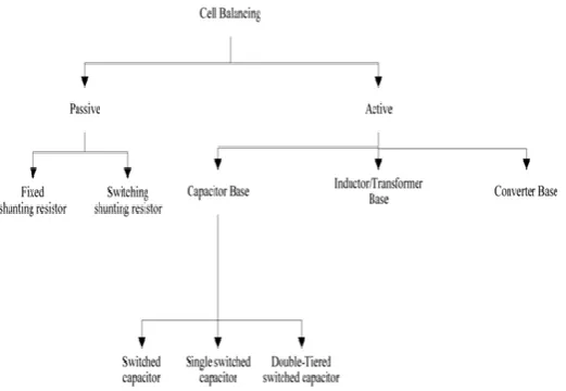
Different cell balancing methodologies have been proposed for the battery pack as shown in the Fig 1. The balancing methods are mainly divided in to two types namely Passive and active cell balancing [8].
Figure 1 Classification of cell balancing
2.3.1.Passive Cell balancing
Passive cell balancing uses a resistor to discharge the cell with the highest cell voltage so that charging can be continued till all cells are fully charged. This method is only suitable during the charging process and not efficient due to power dissipation and energy waste. With active cell balancing, charge can be transferred between the cells in a battery stack using a short time storage element, which can be either a capacitor or an inductor. Fixed shunt resistor method uses continuous bypassing the current for all the cells and the resistor is adjusted to limit the cell voltage. It can only be used in Lead-acid and Nickel based batteries because they can be brought into overcharge conditions without cell damage. This method is simple but energy is dissipated as heat continuously. Shunting resistor method is based on removing the excess energy from the higher cell non continuously but controlled by using switches. It could work in two modes. Continuous- mode and detecting mode. In continuous mode, all the relays are controlled by the same on/off signal. Whereas in detecting mode the cell voltages are monitored and when the imbalance conditions are sensed, a decision is taken to shunt the respective resistors. This method is more efficient than fixed resistor method [9]. Passive cell balancing method is the simplest and cheapest cell balancing method. This method could be operated continuously on each cell independently but this method results in high energy losses, which reduces the energy efficiency.
2.3.2. Active Cell balancing
ISSN: 2393-8366
simultaneously, the balancing must be done sequentially. The charging times for each cell, in the equalization process is very time consuming with charging times measured in hours. There are active cell balancing schemes, which are designed to halt the charging of the fully charged cells and continue charging the weaker cells till they reach full charge thus maximizing the battery’s charge capacity. There are many methods of active balancing. Some of the important options are the following.
Inductive balancing: A multi winding transformer is the key component in this method. Bidirectional equalization capability will assure that all battery cells have uniform charging and that the energy delivered by the battery string is maximized. This topology uses inductors or transformers to move energy from a cell or group of cells to another cell or group of cells. This requires less balancing time. Major disadvantage is high cost of the transformers and requirements of filter capacitors across each battery. DC-DC converter based balancing: It uses a bidirectional DC-DC converter. Initially the cells are divided in to two groups. Part A and Part B. Select the highest cell in part A and the lowest in part B. Turn ON the corresponding Polar switches and control the energy of the DC-DC converter to flow from Part B to Part A, if the highest cell in part B is higher than the lowest one in part A. It has several categories like cuk, buck/boost, fly - back, ramp and full bridge converters. Method of shuttling capacitors: This method utilizes an external energy storage device, capacitor for shuttling energy between the pack cells for the balancing. This can be sub categorized into three: switched capacitor, single switched capacitor, double-tiered switched capacitor .
3 CAPACITIVE SHUTTLING: AN ANALYSIS
3.1 Switched Capacitor
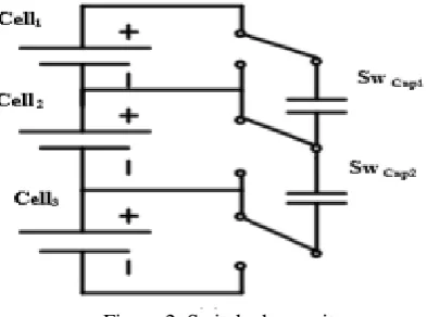
In order to shuttle energy among different cells to keep the voltage balanced this method utilizes external capacitors . The operation principle is very simple. For example in Fig. 3 (a), in one state, Cell1 will be paralleled with SwCap1 and hence SwCap1 will be charged/discharged in order to obtain the same voltage as Cell1. Then the system will turn to the other state where Cell2 also connected in parallel with SwCap1. The cycle repeats and by this process Cell1 and Cell2 are getting balanced. Single switched capacitor uses only 1 capacitor to balance n cells while using n switches whereas, switched capacitor technique utilizes n-1 capacitors and 2n switches to balance n cells (can be batteries as well as SCs). This process reduces the speed of equalization of single switched capacitor as compared to that of the conventional switched capacitor network.
Figure 2 Switched capacitor
ISSN: 2393-8366
3.2 Double-tiered switched capacitor
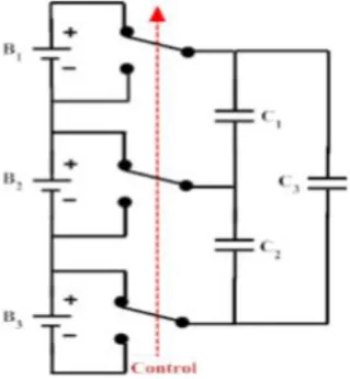
This balancing method is also one of the type of the switched capacitor method, only the difference is that it uses two capacitor tiers for energy shuttling as shown Fig. 3. It needs n capacitor and 2n switches to balance n cells. More tiers means more paths between batteries, which gives small impedance to the transport of charge over a particular distance across the battery pack. Double-tiered switched capacitor circuit operation and control approach is as same as that of the conventional switched capacitor. The only difference between them is the additional tier of capacitors are in parallel with existing capacitors. This ensures the charge exchange between non-adjacent cells in a switching cycle. Therefore, the charge is transferred to far off cells in fewer switching cycles which reduce equalization time. This topology additionally demands n-1 capacitors compared to that of conventional switches while using the same number of switches.
Figure 3 Double tiered switched capacitor
The advantage of double-tiered switched capacitor compared to that of the switched capacitor method is that the second capacitor tier reduces the balancing time for more than a half. Not only that the double-tiered switched capacitor can also work in both charging and recharging operation of capacitor. MATLAB/Simulink becomes the most used software for modeling and simulating systems, here it is used for simulating the switched capacitor balancing methods for constructing the cell balancing. Double-Tiered Switched capacitor (DTSC) battery balancing methods have been simulated using Simulink with the suitable control systems with no load current drawn. DTSC simulation results are shown in Fig. 4. Here, Four 12 Ah Lithium-Ion cells are used for the simulation comparison with a 5% state of charge (SoC) difference between each two neighbored cells[12].
ISSN: 2393-8366
4. PROPOSED SINGLE SWITCHED CAPACITOR METHOD
In this battery management algorithm; a new switched capacitor techniques is explored and is responsible for controlling the charge and discharge currents going into and out of the battery pack. The primary responsibility of the algorithm is to limit the overcharge, over discharge and balance the cells in the pack by maintaining safe operation of the pack; the battery chemistry and hence the spacecraft bus and subsystems. Other important responsibility of this algorithm is cell voltage monitoring battery voltage monitoring and cell bypassing. In the proposed method as the cell balancing is done continuously and is a non dissipative method, the dispersion is minimized continuously and restricted some set value around 10mV and thermal dissipation is reduced significantly and hence more power can be drawn from the battery. The large number of series connected cells are charged continuously by constant current solar array. If the cell voltage falls to a preset UVP limit of 30V the micro controller takes a decision to open the S/C battery discharge relay hence protects the Li-Ion cell from over discharge. If the cell voltage reaches the preset OVP level of 42.5V the controller takes a decision to put off the S/C charger string; to prevent the cells from overcharge. Overcharging even a single cell above this voltage will results in irreversible damage to the entire pack including explosion. Hence a multi level control is programmed in to the controller to include redundancy.
Charge current control is accomplished by charge timer and can be programmed to check the charge and discharge rate of the battery to prevent thermal damage. The controller selects the cell having the highest voltage and allows it to be switched across the lowest cell using a multilevel switch network; till the highest cell fall to an average value or as set by the controller whichever is low. This action continues till the upper set voltage is reached. If the average value is below the previous average; the controller skips the bypass function for that cycle and follow incremental algorithm.
The initial SoC for ten cells of 12Ah capacity is considered as 94 to 99%. This means an SoC differential of 5% and cell voltage differential of 3.9 to 4.1 V for simulation purpose. MOSFET switches are used for simulation having an internal resistance of 50milli ohms. The capacitor used for charge removal from cell having highest voltage is 100uF with an ESR of 30milli ohms. The switches are controlled by the micro controller. Total no. of switches needed for balancing an 'N' cell battery is N+5.The switching frequency is 1KHz with a duty cycle of 45%.The balancing is considered to be completed if the terminal voltage difference among the cell is 10mV or less which corresponds to less than 1% of SOC and the algorithm gets terminated automatically.
Cell balancing is done continuously by using a microcontroller. The controller takes decision to put off and on switch capacitor charger string to prevent cells from over charge and over discharge. The controller selects cell having the highest voltage and allows it to be switched across the lowest cell using a multilevel switch network, till highest cell falls to an average value set by the controller.
ISSN: 2393-8366
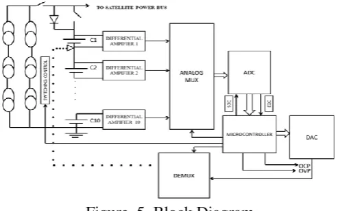
The cell selection for bypass is decided by the controller. The cell having highest voltage is connected to the lowest. To select this DC level, the controller output is connected to a digital to analog converter (DAC). The analog multiplexer is used to reduce the number of channels needed by the ADC. Only one switched capacitor is used to switch between cells. A schematic of the flying capacitor switching scheme is depicted in Fig. 6. The selection of the cells is accomplished by the controller by operating 5 switches in unison and by selecting these switches; the cell with highest voltage gets connected to the capacitor initially and then switches over to the cell having the least voltage. The advantage of this switching network is that it uses only one capacitor to remove and re- use the charges.
Figure 6 Switched Capacitor Network
5. SIMULATION USING SIMULNK MODEL
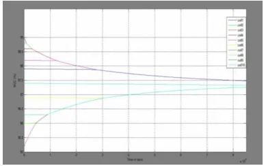
This work presents MATLAB and Simulink simulation of a cell balancing algorithm for Li-Ion cells in a battery pack. One of the method used for balancing is the incremental algorithm during charging of the cells in a battery pack[13]. Initially the cell voltage TMs are read by the software and is compared with the end of charge (EOC) voltage. If any cell voltage is more than the EOC set, that particular cell voltage is replaced with EOC voltage. If the cell voltage is less than EOC; The program finds the lowest and the highest voltage of the cells. The algorithm is made to connect the cell with highest cell voltage to a capacitor through an array of switches. After a predetermined cycle time of around 30 seconds; the capacitor gets connected to the cell having the lowest voltage. The cycle time is programmable through a delay subroutine. The discharge of highest cell voltage is restricted to the average TM voltage; if the current through the MOSFET is of any concern; during switched capacitor charge equalization. In the next cycle; a random number is generated and added with the program run.
Figure 7 Graphical Output of Cell SOC Convergence
ISSN: 2393-8366
is programmed by calling a delay subroutine in the MATLAB S/W. The cell voltages are plotted in each iteration to find total cycle time and charge build up. The shortcoming of the switched capacitor algorithm is its low balancing speed.
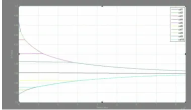
Figure 8 Graphical Output of Cell Voltage Convergence Figure 9 Capacitor Charging and Discharging Curve
The model mainly consists of serially connected ten cells, switching network, capacitor with ESR of 0.1ohms along with the embedded MATLAB function. Ten cells of 12Ah lithium-ion cells are used with initial SoC’s of 99, 98.8, 98.6, 97.4, 98.2, 96.9, 97.9, 96, 95.2 percentages respectively. SoC difference of neighboring cells are 0.2 , 0.2, 1.2, 0.8, 1.3, 1.0, 1.9, 0.8, 1.1 percentages respectively. Ideal switches are used here. Control can be classically performed by using a clock of fixed frequency and duty cycle. SSC balancing control circuit simulated by MATLAB/Simulink program.
Experimental setup is implemented by using Simulink model and coded using program. Single switched capacitor cell balancing can optimize its performance by using more efficient control strategy; conventionally the control of the SSC is based on selecting the high voltage cell and low voltage cell and shutting the energy from the higher cell into the lower one. Balancing is considered to be completed if the terminal voltage difference among the cell is 10mV or less which corresponds to less than 1 percent of SoC and the algorithm get terminated automatically. Experimental results are obtained from the simulation test carried out on 10 series cell rated 12Ah and 3.6V nominal voltage as shown in fig.7, fig.8 and fig.9. In this test the cells are balanced by using SSC balancing systems. The ten cells of 12Ah are realized according to the following condition.
The ten cells started with a voltage of 3.8 to 4.1 the initial SOC of these cells are around 96 to 99 percentage.
The simulation is performed with capacitor of capacitance is1F at a switching frequency of 500 Hz. The time of test is around 24 hours for balancing between cells. The result of simulation is illustrated
in figure
6. CONCLUSION
The microcontroller based Li ion cell balancing using SSC have been discussed in detail which required less system cost and balancing time due to the increased energy transfer between cell and capacitor. The MATLAB simulation of ten cells in series with cell voltage of around 3.9 to 4.2V was done. The voltage comparison and overall monitoring are the mere responsibility of microcontroller. The cell balancing is readily achieved through soft computing of MOSFET. Here the proposed SSC technique was compared with that of double tiered switched capacitor balancing technique to validate the developed battery system model. The main benefits of SSC balancing topology is that it possess optimal weight, low power dissipation and higher efficiency. Overall the proposed technique provide a preliminary check on feasibility and practical implementation of the proposed design.
7. ACKNOWLEDGEMENT
ISSN: 2393-8366
REFERENCES
[1] Timothy Pratl, Charles Bostian and Jeremy Allnutt,"Satellite communications", second edition, Wiley India, New Delhi, 2008.
[2] Jinrong Qian, Yevgen Barsukov, "Battery Power Management for Portable Devices". Artech House Publishers,2013.
[3] SAFT, "Rechargeable Li-ion battery system, Light energy storage for space applications", October 2006.
[4] S.Wenand T.Instruments,“Cell balancing buys extra run time and battery life,” Analog Appl. J.,
2009, Dallas, TX, 1Q.
[5] M. Kultgen, “Managing high-voltage lithium-ion batteries in HEVS,”EDN: Information, News,
and Business Strategy for Electronics Design Engineers, Milpitas, CA, Apr. 2009.
[6] C. Mi, B. Li, D. Buck, and N. Ota, “Advanced electro-thermal modeling of lithium-ion battery
system for hybrid electric vehicle applications,” in Proc. IEEE VPPC, Sep. 9–12, 2007, pp. 107–111.
[7] M. Broussely, P. Biensasn, F. Bonhomme, P. Blanchard, S. Herreyre, K. Nechev, and R. J. Staniewicz, “Main aging mechanisms in Li ion batteries,” J. Power Sources, vol. 146, no. 1–2, pp. 90–
96, Aug. 2005.
[8] J. Guerin and W. Liu, “Cell balancing algorithm verification through a simulation model for
lithium ion energy storage systems,” Soc. Automat. Eng. Int. Conf., 2010, Detroit, MI.
[9] Mohamed Daowd 1, Mailier Antoine 1, Noshin Omar 1,2, Peter van den Bossche 2 and Joeri van Mierlo 1, "Single Switched Capacitor Battery Balancing System Enhancements",2013.
[10] A. Thomas. Stuart, and Wei Zhu, “Fast Equalization for Large Lithium Ion Batteries”,IEEE Aerospace and Electronic Systems Magazine, Vol. 24, pp. 27-31, 2009.