© 2016 IJSRST | Volume 2 | Issue 4 | Print ISSN: 2395-6011 | Online ISSN: 2395-602X Themed Section: Science and Technology
Modelling and Structural Analysis of a Pressure Hull under
Dynamic Load
P. Yamini Charishma
*1, T. R. Sydanna
2, M. Naga Kiran
3, A. Salmon
41,2Department of Mechanical Engineering, JNTUA, Sreenivasa College of Engineering and Technology, Kurnool
Andhra Pradesh, India
3,4
Department Mechanical Engineering, JNTUA, Dr. K.V.Subba Reddy Institute of Technology, Kurnool, Andhra Pradesh, India
ABSTRACT
Pressure hulls are the main load bearing structures of naval submarines, and autonomous underwater vehicles (AUVs). A pressure hull is a structure that is designed to withstand the compressive forces associated with hydrostatic pressure. In this thesis, the assembly of the pressure hull including Navigation compartment shell, Battery compartment shell which is connected with bolts is designed which is used at present. Around 16 M12 bolts are used to connect the Navigation compartment shell and Battery compartment shell. These shells are to be dissembled very frequently for battery charging and other maintenance purpose. It is observed that the dissembling and assembling process is a very time consuming because it requires unbolting and bolting of all the 16 bolts every time. A new design of pressure hull is proposed where the bolts are removed and the navigation compartment and battery compartment are welded. In the present paper, design calculations are done as per ASME codes to withstand the pressure of 65 Bar. The design constraints considered for the analysis were stresses and deflections. The pressure hulls have been modeled considering the elliptical cross section. The modeling of the pressure hull has been carried out by pro-5.0 and analysis software is ANSYS 14.0 software packages
Keywords : Pressure hulls, steel, Static analysis, dynamic analysis.
I.
INTRODUCTION
A light hull (casing in British usage) of a submarine is the outer non-watertight hull which provides a hydrodynamic ally efficient shape. The pressure hull is the inner hull of a submarine; this holds the difference between outside and inside pressure.
SUBMARINE HULL
Type XXI U-Boat, late WWII, with pressure hull almost fully enclosed inside the light hull Modern submarines is usually cigar-shaped. This design, already visible on very early submarines is called a "teardrop hull", and was patterned after the bodies of whales. It significantly reduces the hydrodynamic drag on the sub when submerged, but decreases the sea-keeping capabilities and increases the drag while surfaced.
TYPES
LIGHT HULL
The double hull of a submarine is different from a ship's double hull. The external hull, which actually forms the shape of submarine, is called the outer hull, casing or light hull. This term is especially appropriate for Russian submarine construction, where the light hull is usually made of steel that is only 2 to 4 millimetres thick, as it has the same pressure on both sides. The light hull can be used to mount equipment, which if attached directly to the pressure hull could cause unnecessary stress.
PRESSURE HULL
Inside the outer hull there is a strong hull, or pressure hull, which actually withstands the outside pressure and has normal atmospheric pressure inside. The pressure hull is generally constructed of thick high-strength steel with a complex structure and high strength reserve, and is separated with watertight bulkheads into several compartments. The pressure and light hulls aren't separated, and form a three-dimensional structure with increased strength. The interhull space is used for some of the equipment which doesn't require constant pressure to operate. The list significantly differs between submarines, and generally includes different water/air tanks. Incase of a single-hull submarine, the light hull and the pressure hull are the same.
II.
METHODS AND MATERIAL
A. Specification of the Problem
The objective of the present work is to design and analyses, of steel pressure hull including Navigation compartment shell; Battery compartment shell which is connected with bolts is designed. These shells are to be dissembled very frequently for battery charging and other maintenance purpose. It is observed that the dissembling and assembling process is a very time consuming because it requires unbolting and bolting of all the 16 bolts every time. A new design of pressure hull is proposed where the bolts are removed and the navigation compartment and battery compartment are welded. Pressure hull is a created in Pro-E 5.0. Model is imported in ANSYS 14.0 for analysis by applying normal load and dynamic load conditions. After analyis
a comparison is made between exisisting in terms of deflections and stresses, to choose the best one.
B. Structural Analysis of Pressure Hull
Dimensions of the structural and dynamic analysis the design of pressure hull without bolts and pressure hull with bolts. Pressure hull consists of 5 layers (thickness of each layer, 0.6mm). Diameter of the pressure hull is 125mm. Since the properties of pressure hull vary with directions of a 3-D model of pressure hull is used for analysis in ANSYS 14.0. The loading conditions are assumed to be static and dynamic. The element choosen is SHELL LINEAR LAYER 99, which is a layered version of the 8-node structural shell model. The element has six degrees of freedom at each node: translations in the nodal x, y, and z directions and rotations about the nodal x, y, and z-axes. The finite element analysis is carried out on pressure hull with bolts as well as pressure hull without bolts .From the analysis the equivalent stress (Von-mises stress) and displacements were determined and are shown in figure 2-15. Table 2 - 4 shows the Comparative structural and dynamic analysis of a pressure hull with bolts and without bolts.
C. Specifications of Existing Pressure Hull
Table 1 shows the specifications of a steel pressure hull of alister 3000. The typical chemical composition of the material is 0.565C, 1.8% Si, 0.7%Mn, 0.045%P and 0.045% S.
Sr.no parameters value 1 Total length of pressure
hull(Eye to Eye)
245mm
2 Diameter of pressure Hull 125 mm
3 Thickness of pressure Hull 3 mm
4 Applying the pressure 6.326 N/mm2
5 Young’s modulus of steel 2.1e5 N/mm2 6 Density of pressure Hull 7860 kg/m3
7 Yield strength 500 N/mm2
8 Tensile strenth 620 N/mm2
D. Structural and Dynamic Analysis of Pressure Hull
A. Pressure Hull with Bolts
Figure 2. Analysis of pressure hulls without bolts
1. Structural Analysis
Figure 3. stress distribution for pressure hulls
Figure 4. Displacement pattern for pressure hulls
2. Dynamic Analysis : 10 Secs
Figure 5. Stress distribution for pressure hulls
Figure 6. Displacement pattern for pressure hulls
3. Dynamic Analysis : 20 Secs
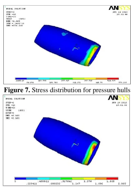
Figure 7. Stress distribution for pressure hulls
B. Pressure Hull with Out Bolts
Figure 9. Analysis of pressure hulls without bolts 1. Structural Analysis
Figure 10. Stress distribution for pressure hulls
Figure 11. Displacement pattern for pressure hull
2. Dynamic Analysis : 10 Secs
Figure 12. Stress distribution for pressure hulls
Figure 13. Displacement pattern for pressure hulls
3. Dynamic Analysis : 20 Secs
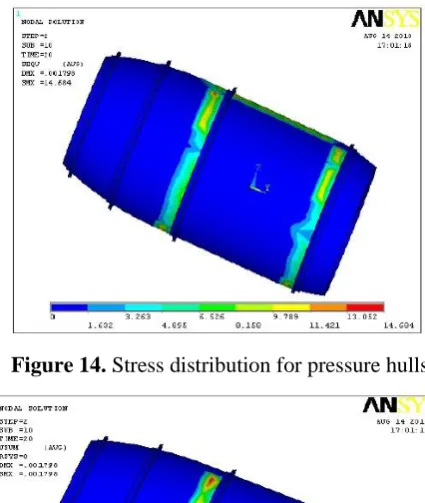
Figure 14. Stress distribution for pressure hulls
Figure 15. Displacement pattern for pressure hulls
III.
RESULT AND DISCUSSION
A. Structural Analysis Results
Sr. No PH Stress (N/mm2)
Displacement mm
Strain
1 WB 288.579 1.029 0.001861 2 WOB 7.341 0.000657 0.000046
Notes: 1. PH = pressure hull 2. WB = with bolts 3. WOB = without bolts.
1. Dynamic Analysis Results
Table 3 : Comparative dynamic analysis of a pressure hull with bolts and without bolts.
Sr. No parameters Time PHWB PHWOB
1 STRESS
(N/mm2)
10 sec 288.97 7.341
20 sec 578.289 14.684 30 sec 867.749 22.06 2 Displacement
(mm)
10 sec 1.031 0.000899
20 sec 2.065 0.001798
30 sec 3.099 0.002697
3 Strain 10 sec 0.001863 0.000046
20 sec 0.003729 0.000094
4 STRESS
(N/mm2)
10 sec 288.97 7.341
30 sec 0.005595 0.000141
Notes: 1. PHWB = pressure hull with bolts, 2. PHWOB = pressure hull without bolts.
2. Modal Analysis Results
Table 4 : Comparative modal analysis of a pressure hull with bolts and without bolts
Sr.No PH with bolts PH Without bolts
Displace ment (mm) Frequenc y (Hz) Displacem ent (mm) Frequency (Hz)
1 1.0029 0 0.218416 0 2 0.32194 21.646 0.19668 0 3 0.23168 25.742 0.10598 0.000007 4 0.276541 26.2929 0.228769 0.0000081
Notes: 1. PHWB = pressure hull with bolts, 2. PHWOB = pressure hull without bolts
B. Graphs
Pressure Hull with bolts and without bolts for dynamic analysis
Figure 16. Time – Displacement curves for PHWB AND PHWOB
Figure 17. Time – Displacement curves for PHWB AND PHWOB
Notes: 1. PHWB = pressure hull with bolts, 2. PH WOB = pressure hull without bolts, 3. Series 1 = PHWB curve
4. Series 2 = PHWOB curve
IV.
CONCLUSION
To observer the all results and to compare the pressure hull with bolts and without bolts with respect to weight, stiffness and strength.
By employing the pressure hull without bolts for the same load carrying capacity, there is reduction in are 32%- 41% higher than pressure hull with bolts and 52%- 63% stiffer than pressure hull with bolt.
and pressure hull without bolts. Based on the results, it was inferred that pressure hull without bolts has superior strength and stiffness and lesser in weight compared to pressure hull with bolts.
From the results, it is observed that the pressure hull without bolts is lighter and more economical than the conventional pressure hull with bolts with similar design specifications
V.
REFERENCES
[1] Tsybenko A.S., Kuranov B.A., Chepurnoi A.D., Krishchuk N.G. &Shtefan E.V., State of Stress and Strain of Pressure Vessel during
Pressurization, Plenum Publishing
Corporation(1989).
[2] Liang C.C., Optimum Design of Filament-wound Multilayer- sandwich Submersible Pressure Hulls, Pergamon Ocean Engineering,30 (2003) 1941-1967.
[3] Ross C.T.F., A Conceptual Design of an Underwater Vehicle, Elsevier Ocean Engineering, 33 (2006) 2087-2104.
[4] Ross, C.T.F., A Conceptual Design of an Underwater Missile Launcher, Elsevier Ocean Engineering, 32 (2005) 85-99.
[5] Ross C.T.F. & Etheridge J., The Buckling and Vibration of Tube-stiffened Axisymmetric Shells under External Hydrostatic Pressure, Pergamon Ocean Engineering, 27 (2000) 1373-1390.
[6] Ross C.T.F., Little A.P.F. &Adeniyi K.A., Plastic Buckling of Ring-stiffened Conical Shell under External Hydrostatic Pressure, Elsevier Ocean Engineering, 32 (2003) 21-36.
[7] Ross C.T.F., Little A.P.F. & Leonidas Chasapides, Jeff banks, and Daniele Attanasio, Buckling of Ring Stiffened Domes under External Hydrostatic Pressure: Science Direct Ocean Engineering, 31 (2002) 239-252.
[8] Ross C.T.F. & Little A.P.F., The Buckling of a corrugated Carbon Fiber Cylinder under External Hydrostatic Pressure, Elsevier Ocean Engineering, 28 (2001) 1247-1264.
[9] Blachut J. & Smith P., Buckling of multi-segment underwater pressure hull, Elsevier Ocean Engineering, 35 (2007) 247-260.
[10] Derek Graham, Predicting the collapse of externally pressurized ring-stiffened cylinders