Methodology for assessing impact damage using integrated
simulation and experimentation
M. Feligiotti1a, E. Hack1, and G. Lampeas2
1Laboratory Electronics/Metrology/Reliability, EMPA, CH-8600 Dübendorf, Switzerland 2Laboratory of Technology and Strength of Materials, Mechanical Engineering and Aeronautics
dept., Univ. Patras, 26500 Rion, Greece
Abstract. The investigation of damage induced by dynamic events is since many years of central interest especially to increase safety and security of all means of transportation. The use of integrated full-field optical methods and FEM analysis gives good results in investigating damage produced after impact. In this paper a methodology for assessing impact damage using both simulation and experimentation will be presented. The methodology considers the effect of the defect presence on different parameters (e.g. geometrical parameters, strain field, dynamic parameters). Although a number of possible approaches in providing FEM and measurement results are being investigated, a general procedure to compare the data has been identified and includes the possibility of using reduced or decomposed data for the comparison of results from experimentation and simulation.
1 Introduction
In the last few years interest has been directed to the development for techniques investigating damage induced by dynamic events. Most of these techniques make use of full-field optical methods of deformation measurement to experimentally validate simulations of dynamic events. Applications include vehicle structures that have been damaged in-service, for which the identification and characterization of damage will likely be followed by a structural prognosis and a decision on continued operation/repair/retirement. The motivation for ADVISE [1] is to enable higher quality structural prognosis, and one of the objectives is to develop a methodology for assessing impact damage helping in the reliable prediction of the residual life of a structure.
The establishment of a methodology for integrating experimental and simulation results has been initiated. Development of both numerical and experimental studies has been carried out in order to achieve high levels of confidence when the results are compared. The evaluation of different approaches for damage detection and assessment, reported in the literature, has assisted with the development of the final methodology.
a
e-mail : [email protected]
© Owned by the authors, published by EDP Sciences, 2010 DOI:10.1051/epjconf/20100646008
EPJ Web of Conferences 6, 46008 (2010) 6
2 General overview of the methodology
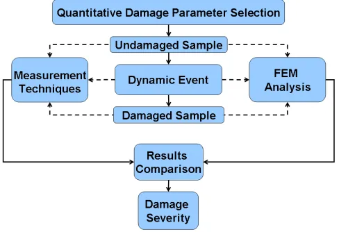
The approaches evaluated show a common structure that can be summarized in a schematic manner as in Figure 1. The first step is the proper selection of the parameter/s capable of describing the damage in a quantitative manner. The parameter can be a geometrical one (e.g. shape of defect, crack length, delamination area and width) but can also be a parameter related to the response of the structure (e.g. strain field, curvature, mode shape). Relating the parameter value to the size of the defect enables to predict the severity of the damage. Once the parameter is chosen, the attention can be focused on how to obtain comparable results from measurement techniques and FEM analysis.
In Figure 1 the full arrows indicate the path that all procedures have in common; the dashed arrows show the different ways that can be followed to achieve a characterisation of the damage.
Fig. 1. General Methodology.
Three different classes of approach can be distinguished:
• First approach: comparison of the values of selected parameter measured experimentally and simulated by FEM analysis during the dynamic event
• Second approach: comparison of the values of selected parameter measured experimentally and simulated by FEM analysis in an undamaged and a damaged sample
• Third approach: comparison of the resulting characteristic of the damage measured
experimentally and simulated by FEM analysis
In the first approach the FEM analysis must be carried out for the dynamic event itself, and the measurements during the dynamic event. In the second approach, focus is on the damage. Measurements and FEM analysis are performed on undamaged and on damaged samples without considering the details of the dynamic event. While in these two approaches the investigated parameters are not related to the geometry of the defect, the third approach is focused on the comparison of damage geometry obtained from measurements and FEM analysis. In the next paragraphs the three different approaches will be analysed in more detail. A schematic view will be presented in order to facilitate the comprehension of the three different approaches.
The last step of the methodology is the comparison of the results. It is noticeable that in many papers the comparison between FEM and experimental results is often restricted to a qualitative comparison. The purpose of ADVISE is to find a methodology capable of assessing the damage and making use of a quantitative comparison between FEM and full-field experimental results.
Performance Space Structure Systems GmbH (HPS) (Figure 3). A drop-weight impact tower is used to reproduce dynamic events and to damage the samples. FEM analyses of the specimens are carried out in order to provide data for comparison with the experimental results.
Fig.
2
. Flat panels in Polypropylene Long Glass Fiber and Polyamide Short Glass Fiber (CRF)a) Panel during impact test
b) Upper skin after impact
c) Lower skin after
impact d) FEM model Fig. 3. Sandwich panel(HPS)
3 Quantitative Damage Parameter Selection
In the first step of the methodology the right parameter/s capable of describing the damage are chosen. Several parameters can be considered: strain field, mode shape, curvature, as well as geometrical parameters (e.g. area or diameter of the delamination, crack length). However, the main issue is which one of these parameters can best represent the behaviour of the structure when damage evolves. Monitoring the parameter and recording changes in its value should not only indicate the presence of a defect but should help in assessing the health of the structure making more evident the decision to leave it in service, to repair it, or to completely dispose of it. At the moment it is common practice to locate a defect in a structure using one of the many measurement techniques available for damage inspection. However, the relation between damage and the corresponding condition or reliability of the structure is often very difficult to establish [2].
Each parameter presents distinct characteristics and can be used in the methodology. However advantages and disadvantages of each parameter must be investigated in order to choose the best parameter for damage assessment.
The geometrical characteristics make immediately understandable the extent of the damage, especially for big defects, which are easily detected. However, in most cases the defects are small and even with the support of non-destructive measurement techniques the estimation of their exact geometry is very complicated (e.g. length of a small crack). From this point of view the defect itself seems not to be an exhaustive parameter since it does not provide any further information about the
a) Panel during impact test b) PP after impact
c) PA after impact
health condition of the structure. This limits the use of a damage characterisation approach by way of direct comparison of defect shape.
It is well known, that when damage is present in a structure it alters its dynamic characteristics such as frequency response functions and modal parameters. Several full-field optical techniques focus on determining the existence of damage making use of dynamic parameters. FEM modal analysis can be carried out to obtain comparable results helping with the identification of the location and size of the defect. The damage can be detected when the measured and simulated dynamic parameter deviates appreciably from the value expected for a healthy structure. Many studies show how these parameters produce satisfactory damage diagnoses with an acceptable level of accuracy [3-5]. However the modal parameters are linked to the out of plane displacement, so that the behaviour of the structure is well known only in one direction. Furthermore, the modal analysis response is very sensitive to many other parameters apart from defects, e.g. loading and boundary conditions which might interfere and results in difficulties in the separation of the influence of the defects on the response.
The influence of damage on the strain distribution after the damage-inducing event seems to be one of the most relevant considerations for evaluating the residual life of a structure. Several studies describe structural health monitoring assessment approaches based on strain comparison between values from FE prediction and experimental measurements [6-9].
It has to be taken into account that strain is a derived quantity, since FEM is based on calculations of displacement at the nodes and many optical techniques like DSPI or Image Correlation have displacement components as the primary output. This means that validation through strain values affects the comparison of uncertainties related to strain calculation (both from numerical differentiation as well as from image analysis). Therefore it seems obvious that validation through displacement values is more appropriate. However, displacement components can contain rigid body displacements from potential object movements. Consequently, a simple interpretation of displacement maps is not possible in many cases. In contrast, strain data is free of rigid body movements. Moreover strain rather than stress is chosen to be plotted as FEM and measurement results. All these reasons make the strain a suitable parameter for damage assessment [10].
4 Different approaches to provide measurement and FEM results
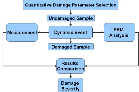
4.1 First Approach
In the first approach the measurements and the FEM analysis are performed during the dynamic event. Figure 4 shows a flowchart of the approach.
The parameter (e.g. strain) is measured during the impact test, e.g. by piezoelectric sensors [11], by strain gauges [12] or by digital image correlation [13] as in the ADVISE project. In particular in this paper an impact test by use of a drop tower has been carried out on the above mentioned sandwich honeycomb panel (Figure 3). The strain histories have been recorded during the impact by use of a Digital Image Correlation system and they have been compared with the one numerically calculated by FEM analysis. This paper provides a valid support of the approach.
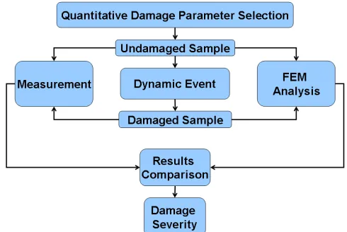
4.2 Second Approach
Characterisation of a defect can be done by analysing a sample before the dynamic event without defect and then after the dynamic event with the presence of a defect. In Figure 5 a flowchart of the second approach is shown.
Fig. 5. Flowchart of Second Approach.
Initially, the parameter that will be investigated is chosen (e.g. modal parameter [14-16], strain [17]). The parameter value should change in the presence of the defect, so that the change can be derived from the measurements and the FEM analysis of an undamaged and damaged specimen. Comparing the values obtained from both measurement and FEM analysis it is possible to better understand the damage severity. Since the FEM analyses are performed on damaged specimens, the geometry of the defect has to be known (e.g. by conducting an inspection with full field optical techniques on the damaged specimen) and it has to be introduced in the FEM model.
4.3 Third Approach
Fig. 6. Flowchart of Third Approach.
5 Results comparison
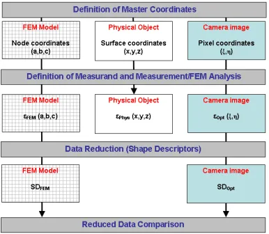
The crucial point of the methodology for assessing impact damage is the rigorous comparison of experimental and simulation data. The feasibility study on data comparison with simulated results achieved in the SPOTS project, is the starting point to build a new methodology suitable for dynamic events, as required by the ADVISE project. The flowchart in Figure 7 helps to understand how the comparison is performed.
Fig. 7. Flowchart of results comparison
5.1 Definition of master coordinates
5.2 Definition of measurand and measurement/FEM analysis
This step resumes topics already well discussed in the previous paragraphs: the definition of the parameter and the different manner how to perform FEM analysis and measurements. In particular here the measurand has been denoted by ε, which identifies a strain component. Once measurements and FEM analysis are performed, the strain components are related to the three entities: FEM model
εFEM (a,b,c), Physical object εPhys (x,y,z) and camera image εOpt (ξ,η). It is noticeable how at this step
the results are still linked to the coordinate systems.
5.3 Data Reduction
Detailed finite element models and advanced full-field optical measurement techniques make accurate dynamic characteristics available for large and complicated structures. It means that a comparison between FEM analysis and measurement results involves a large amount of data. To reduce the amount of the data, it is possible to extract from them a number of shape features with good discriminative capability, in order to form a feature vector called the shape descriptor (SD). The functionality of shape descriptors in particular the Zernike moment descriptor and the Fourier descriptor are well described [21], providing evidence of how these shape descriptors can strongly reduce the amount of the data.
In this step the presence of the Physical Object is not essential anymore, assuming that the FEM model and the camera image are representative of the physical object (e.g. by calibration). As a consequence the data reduction concerns the strain field coming from the FEM model (SDFEM) and
the camera image (SDOpt). It is noticeable that the dependence from the coordinate systems
disappears, according to the property of shape descriptors.
5.4 Reduced Data Comparison
Once the data reduction is accomplished and the SDs are available, the comparison between FEM analysis and measurements results can be performed making a statistical comparison from the shape descriptors, the technique is discussed in [21]. The presence of a defect in the system modifies the SDs, making visible the damage. The comparison between SDs related to the FEM analysis and measurement results become then a valid support to evaluate the severity of the damage.
6 Conclusions
The establishment of a generalized methodology for assessing impact damage integrating experimental and simulation results has been proposed. Although a number of possible methods in providing FEM and measurement results are being investigated when impact damage occurs, a general approach has been identified. In particular the methodology takes care of selecting the parameter that has to be investigated (e.g. shape of defect, strain field, modal parameters) and includes the possibility of using reduced or decomposed data (SDs) for the comparison of results from experimentation and simulation. The comparison of the SDs related to the measured and simulated results will facilitate the understanding of damage severity since sensible changes are recorded when damage occurs.
Acknowledgements
7 References
1. ADVISE – Advanced Dynamic Validations using Integrated Simulation and Experimentation, FP7 project SCP7-GA-2008-218595
2. F. Necati Catbas, A. Emin Aktan, Condition and Damage Assessment: Issues and Some Promising Indices, Journal of Structural Engineering, Vol. 128, No. 8, (2002)
3. P. Qiao, K. Lu, W. Lestari, J. Wang, Curvature mode shape-based damage detection in composite laminated plates, Composite Structure 80, 409-428, (2007)
4. Myung-Keun Yoon, D. Heider, J.W. Gillespie Jr, C.P. Ratcliffe, R.M. Crane, Local Damage Detection with the Global Fitting Method Using Mode Shape Data in Notched Beams, J Nondestruct Eval 28, 63-74 (2009)
5. S.S. Kessler, S.M. Spearing, M.J. Atalla, C.E.S. Cesnik, C.Soutis, Damage detection in composite materials using frequency response methods, Composites. Part B 33, 87-89, (2002)
6. H.C.H. Li, I. Herszberg, C.E. Davis, A.P. Mouritz, S.C. Galea, Health monitoring of marine composite structural joints using fibre optic sensors, Composite Structures 75, 321-327, (2006)
7. Rodrigo A. Silva-Muñoz, Roberto A. Lopez-Anido, Structural health monitoring of marine composite structural joints using embedded fiber Bragg grating strain sensors, Composite structure 89, 224-234, (2009)
8. Ch.E. Katsikeros, G.N.Labeas, Development and validation of a strain-based Structural Health Monitoring system, Mechanical System and Signal Processing 23, 372-383, (2009)
9. D. Maity, A. Saha, Damage assessment in structure from changes in static parameter using neural networks, Sadhana - Academy Proceedings in Engineering Sciences, Vol. 29, Part.(3), pp.315-327 (June 2004)
10.SPOTS: Standardisation project for optical techniques of strain measurement, EU contract no. G6RD-CT-2002-00856, see http://www.opticalstrain.org
11.S.E. Watkins, F. Akhavan, R. Dua, K. Chandrashekhara, D. Wunsch, Impact induced damage characterization of composite plates using neural networks, Smart Material and Structures, 16, 515-524 (2007)
12. P.M. Schubel, J. Luo, I.M. Daniel, Low velocity impact behaviour of composite sandwich panels, Composites: Part A 36, 1389-1396, (2005)
13.G. Lampeas, T. Siebert, Validation of non-linear dynamic simulations through full field optical methods, paper No. 321, ICEM14 Conference, (Poitiers, France, 2010)
14.M.N. Helfrick, P. Pingle, C. Niezreck, P. Avitabile, Using Full-Filed Vibration Measurement Techniques for Damage Detection, Proceeding of the IMAC-XXVII, (Orlando, Florida, 2009)
15. P. Qiao, W. Lestrai, M.G. Shah, J. Wang, Dynamics-based Damage Detection of Composite Laminated Beams using Contact and Noncontact Measurement Systems, Journal of Composite Materials, Vol. 41, No 10, (2007)
16.H. Hu, J. Wang, Damage detection of a woven fabric composite laminate using a modal strain energy method, Engineering Structures 31, 1042-1055, (2009)
17.N. Ramanujam, T. Nakamura, Estimating Surface Damage of Composite Panels with Inverse Analysis, Journal of Composite Materials, Vol. 41, No. 20, pp. 2471-2498, (2007)
18. F. Aymerich, F. Dore, P. Priolo, Simulation of multiple delaminations in impacted cross-ply laminates using a finite element model based on cohesive interface elements, Composites Science and Technology, 69, 1699-1709(2009)
19.M. Guida, F. Marulo, M. Meo, M. Riccio, Analysis of Bird Impact on a Composite Tailplane Leading Edge, Appl Compos Mater 15, 241-257, (2008)
20.W. Hufenbach, N. Petrinic, A. Hornig, A. Langkamp, M. Gude, J. Wiegand, Delamination Behaviour of 3D-Textile Reinforced Composites- Experimental and Numerical approaches,
Conference on Damage in Composite Materials: Impact and delamination Prediction (CDCM06), (Stuttgart, 2006)