IJEDR1704031
International Journal of Engineering Development and Research (www.ijedr.org)
201
Modelling of PR Controller For A Grid Connected
Single Phase Inverter
1Gandham Krishna Kanth, 2T Lova Lakshmi, 3M Gopichand Naik 1PG scholar, 2Research scholar, 3Associate professor
1Department of Electrical Engineering, 1Andhra University, Visakhapatnam, India
________________________________________________________________________________________________________
Abstract—Single-phase grid-connected inverters are widely used to connect small-scale distributed renewable resources to the grid. However, unlike a three-phase system, control for a single-phase inverter is more challenging, especially when the inverter is used with an LCL filter. This paper proposes the modelling of PR (proportional resonant) controller for a grid connected single phase inverter and observation of its performance during load fluctuation condition. From Simulation results of the system it is demonstrated that the modelled PR controller exhibits good transient response over the conventional PI controller when system subjected to load disturbance.
Index Terms— Single phase inverter, LCL filter, PR controller, PI controller, current control loop.
________________________________________________________________________________________________________
I.INTRODUCTION
In recent years, distributed generation has been put on the agenda, distributed generation has the merits of less pollution, high reliability, high energy efficiency and installation flexibility, it can solve many potential problems of the large scale centralized power effectively, however, electricity produced by distributed power generation can’t supply to AC load directly, grid-connected interface equipment must be inserted[7].
Power inverter is an important part of many DC to AC conversion equipments such as uninterruptable power supply (UPS), induction motor drive and automatic voltage regulator (AVR) systems. In these systems, it is the major requirement for the power inverter to be capable of producing and maintaining a stable and clean sinusoidal output voltage waveform regardless of the type of load connected to it. The main key to successfully maintain this ability is to have a feedback controller.
Currently, grid-connected inverter generally use control strategy of the output current control, nowadays, the most commonly used method have PI control[6] and so on. It has the merits of good control performance, robustness, and simple algorithm, clear physical meanings of parameters, easy to implement and high reliability, so it is widely applied in industry field as yet but conventional control can't reach perfect control effects for sine reference current, because this method has relatively more rise and settling time. In order to settle this problem, PR controller is designed in this paper. PR-controllers provide theoretical infinite gain in a narrow bandwidth that is centered at a predefined resonance frequency, hence eliminating the steady state error at that frequency and allowing effective tracking behavior with sinusoidal reference signals. Another advantage associated with the PR controllers is the possibility of implementing certain harmonics compensation without requiring excessive computational resources. This controller is highly suited to operate with sinusoidal references like the reference used in Grid-Connected PV Inverters, thus making it an optimal solution for this application.
II.SINGLEPHASEGRIDCONNECTEDINVERTER
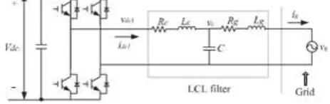
Figure 1, shows the schematic circuit diagram of a single-phase full bridge inverter with connected to grid. In this study, control based on the PR strategy theory is presented.
Fig.1 Schematic diagram of grid connected single phase inverter
A full bridge configuration with sinusoidal pulse width modulation (SPWM) unipolar voltage switching scheme is used as the switching circuit of the inverter. By selecting the full bridge configuration, the minimal allowed DC-link voltage can be set to be the peak value of the AC grid voltage (plus margins). In this, power IGBT is used in order to get high switching frequency with minimal switching losses as IGBT provides high switching character of MOSFET and minimal switching losses of BJT.
A. output filter design
IJEDR1704031
International Journal of Engineering Development and Research (www.ijedr.org)
202
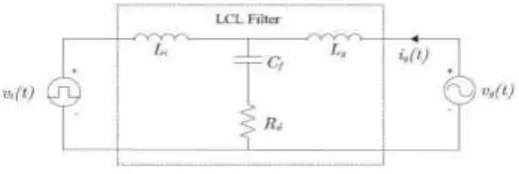
Figure.2: interconnection diagram of LCL filter
Here vt(t) represents the inverter output voltage which acts as input to the filter consists of a fundamental component and higher,
vg(t) is the grid voltage and ig(t) is the grid current. Analyzing the filter in the s-domain gives the following transfer function equations
At 𝑣𝑔= 0
Ig(s)
Vt(s)= −
sCfRd+1
s3LiLgCf+s2CfRd(Li+Lg)+s(Li+Lg) (1) At 𝑉𝑡= 0
𝐼𝑔(𝑠)
𝑉𝑔(𝑠)=
𝑠2𝐿𝑖𝐶𝑓+𝑠𝐶𝑓𝑅𝑑+1
𝑠3𝐿𝑖𝐿𝑔𝐶𝑓+𝑠2𝐶𝑓𝑅𝑑(𝐿𝑖+𝐿𝑔)+𝑠(𝐿𝑖+𝐿𝑔) (2)
Therefore, Equation (1) is used as the transfer function of the filter from the filter circuit. From equation (1) we can calculate the resonant frequency of the filter which is 𝜔𝑟 and
𝜔𝑟= √
(𝐿𝑖+𝐿𝑔)
𝐿𝑖𝐿𝑔𝐶𝑓
Finally, the LCL filter components are chosen following this guideline and the values of each component are shown in Table.1
Table 1: filter design parameters III.CONTROLLERMODELLING
A.Proportional resonant controller
The current controller can have a significant effect on the quality of the current supplied to the grid by the PV inverter, and therefore it is important that the controller provides a high quality sinusoidal output with minimal distortion to avoid creating harmonics
A single phase feed back current loop is used to regulate the grid current. A proportional resonant control strategy is used as compensator to track a sinusoidal current reference frame. The basic control loop diagram[4] with PR control is as shown in figure 3.
Fig. 3 control loop diagram with PR controller Transfer function of the ideal PR controller is as below:
𝐺𝑃𝑅(𝑠) = 𝐾𝑝+ 𝐾𝑅 𝑠 𝑠2+𝑤
𝑜2 (3) Where 𝐾𝑝− proportional gain of the controller
𝐾𝑅−resonant gain of the controller
𝑤𝑜− resonant frequency of the controller in general which is frequency of the grid
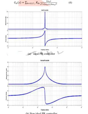
Unfortunately, the ideal PR controller acts like a network with an infinite quality factor, which is hard to implement the PR controller in reality. Firstly, the infinite gain introduced by PR controller leads to an infinite quality factor which cannot be achieved in either analog or digital system.
Secondly, the gain of PR controller is much reduced at other frequencies and it is no adequate to eliminate harmonic influence caused by grid voltage. Therefore, an approximating ideal (non-ideal) PR controller, is given by
Filter element Value
Li- inverter side inductor 15.7mH
Lg-grid side inductor 0.57mH
Cf-filter capacitance 10𝜇F
IJEDR1704031
International Journal of Engineering Development and Research (www.ijedr.org)
203
𝐺𝑃𝑅(𝑠) = 𝐾𝑝+ 𝐾𝑅2𝜔𝑐𝑠
𝑠2+2𝜔𝑐𝑠+𝑤𝑜2 (4) Where 𝜔𝑐- bandwidth around the ac frequency of 𝑤𝑜
The frequency response of (4) is shown in Fig. 3(b), where the resonant peak now has a finite gain of 40 dB which is satisfactorily high for eliminating the voltage tracking error. In addition, a wider bandwidth is observed around the resonant frequency, which minimizes the sensitivity of the controller to slight grid frequency variations. At other harmonic frequencies, the response of the non-ideal PR controller is comparable to that of the ideal PR controller.
B.PR Controller with compensator
In order to reduce the harmonics generated during load fluctuations within short time interval we use PR harmonic compensator[4,5] along with our PR controller. The basic control loop diagram of PR with compensator as shown in figure 4
IV.
Fig. 4 control loop diagram of PR controller with compensator.
The harmonic compensator GH (s) is represented by
𝐺𝐻(𝑠) = ∑ 𝐾𝑙ℎ
𝑠 𝑠2+(ℎ𝜔𝑜)2
ℎ=3,5,7,.. (5)
Where 𝐾𝑙ℎ resonant gain term of particular harmonic and ℎ𝜔𝑜 is the resonant frequency of that harmonic.
Eq. (5) represents an ideal harmonic compensator which as stated for the fundamental PR controller, can give stability problems due to the infinite gain. To avoid these problems, the harmonic compensator equation[9] can be made non-ideal by representing it using (6)
𝐺𝐻(𝑠) = ∑ 𝐾𝑙ℎ
2𝜔𝑐𝑠
𝑠2+2𝜔𝑐𝑠+(ℎ𝜔𝑜)2
ℎ=3,5,7,.. (6)
(a) ideal PR controller
(b) Non ideal PR controller
IJEDR1704031
International Journal of Engineering Development and Research (www.ijedr.org)
204
From the below frequency responses we can observe the variations in the performance and stability of the PR controller with the variation of controller gains and parameters.Based Based on the theory analysis, in this paper, the PR controller gains are chosen as: Kp = 6.8, KR = 1498.72 and ωcut = 0.5(rad/s).
(a) Frequency response when Kp changes
(b) Frequency response when Kr changes
(c) Frequency response when 𝜔𝑐𝑢𝑡 changes
Fig.6 Frequency responses of a non ideal PR controller for changes in (a)Kp (b)Kr (c)𝜔𝑐𝑢𝑡
Load disturbance:
IJEDR1704031
International Journal of Engineering Development and Research (www.ijedr.org)
205
controller[8] makes much difference in the system which severely influences the settling time, fluctuations of the system parameters and system stabilityIV SIMULATION AND RESULTS
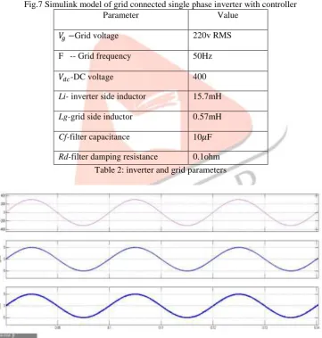
Figure 7 below shows the basic Simulink model of the implemented single phase inverter connected to grid along with the controller. The parameters taken into consideration for the implementation of grid are listed in table 2.
Fig.7 Simulink model of grid connected single phase inverter with controller
Table 2: inverter and grid parameters
Fig.8: Steady state a)grid voltage b)grid current c)inverter current .
Parameter Value
𝑉𝑔−Grid voltage 220v RMS
F -- Grid frequency 50Hz
𝑉𝑑𝑐-DC voltage 400
Li- inverter side inductor 15.7mH
Lg-grid side inductor 0.57mH
Cf-filter capacitance 10𝜇F
IJEDR1704031
International Journal of Engineering Development and Research (www.ijedr.org)
206
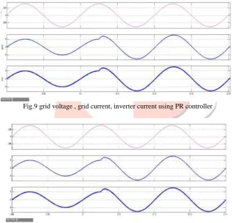
Fig.9 grid voltage , grid current, inverter current using PI controller.Load fluctions on the system clearly showing the variations in grid current , inverter current and also we can observe the settling time taken by the system in order to settle down the load disturbance occurred
Fig.9 grid voltage , grid current, inverter current using PR controller
Fig. 10 grid voltage , grid current, inverter current using PR controller with compensator V. CONCLUSION
The modelling of PR (proportional resonant) controller for a grid connected single phase inverter and observation of its performance during load fluctuation condition is done using MATLAB/Simulink. From Simulation results of the system it is demonstrated that the modelled PR controller exhibits good transient response over the conventional PI controller when system subjected to load disturbance. The better performance is obtained using harmonic compensator along with the modelled PR controller.
VI. REFRENCES
[1]. N. Zhang, H. Tang, and C. Yao, “A systematic method for designing a PR controller and active damping of the LCL filter for single-phase grid- connected PV inverters,” Energies, vol. 7, no. 6, pp. 3934–3954, Jun.2014.
[2]. W. Wu, Y. Sun, Z. Lin, T. Tang, F. Blaabjerg, and H. S. Chung, “A new LCL-filter with in-series parallel resonant circuit for single-phase grid- tied inverter,” IEEE Trans. Ind. Electron, vol. 61, no. 9, pp. 4640–4644, Sep. 2014.
IJEDR1704031
International Journal of Engineering Development and Research (www.ijedr.org)
207
[4]. Daniel Zammit , Cyril Spiteri Staines, Maurice Apap, John Licari “Design of PR current control with selective harmoniccompensators using Matlab”, press aricle, 10 jan.2017.
[5]. S. B. Kjaer, J. K. Pedersen, and F. Blaabjerg, “Linear current control scheme with series resonant harmonic compensator for single-phase grid- connected photovoltaic inverters,” IEEE Trans. Ind. Electron., vol. 55, no. 7, pp. 1292–1306, Jul. 2008.
[6]. “Design of a Current Mode PI Controller for a Single-phase PWM Inverter” 2011 IEEE Applied Power Electronics Colloquium (IAPEC).
[7]. S. Kjaer, J. Pedersen, and F. Blaabjerg, "A review of single-phase inverters for photovoltaic modules," Industry Applications, IEEE Transactions on, vol. 41, no. 5, pp. 1292-1306, sept.-oct. 2005.
[8]. Zammit, D., Spiteri Staines, C., Apap, M., 2014. Comparison between PI and PR current controllers in grid connected PV inverters, WASET. Int. J. Electr. Electron. Sci. Eng. 8 (2).