Research on On-card Bytecode Verifier for Java
Cards
Tongyang Wang, Pengfei Yu, Jun-jun Wu and Xin-long Ma
Institute of Information & System Technology,Huazhong Univ. of Sci & Tech.,Wuhan 430074, China Email: [email protected]
Abstract—The bytecode verification is a key point of the
security chain of the Java Platform. This feature is optional in many embedded devices since the memory requirements of the verification process and the process capability of hardware are too high. In this paper we propose a verifier that utilizes the logical flow graph based cache policy and an improved non stressing type coding method, for the bytecode verification on the Java card, which remarkably reduces the use of the memory by the scheduling algorithm of the bytecode verifier. Off-card pre-processing is unnecessary for the bytecode, hence it is possible to be implemented on card and to prevent any bytecode, which is correct yet not pre-processed, from being refused by the on-card verifier. This algorithm also features strong transportability and feasibility with a perfect verification process based on traditional bytecode verification. The results of the experiments show that this bytecode verification can be performed directly on small memory systems.
Index Terms—java card, bytecode verification, type
deduction, cache scheduling policy
I. INTRODUCTION
The Java programming language was born in the early 90s in order to meet flexible and highly reliable smart electronic device programming requirements. It is used in a growing number of fields and lately also in the embedded system world.
Actually, a Java Card is a Smart Card running a Java Virtual Machine (VM), the Java Card Virtual Machine (JCVM), and it is going to become a secure token in various fields, such as banking and public administration. The JCVM is the core of the Java Card: it is a software CPU with a stack based architecture that creates an execution environment between the device and the programs (Java Card Applets). The JCVM guarantees hardware-independence and enforces the security constraints of the sandbox model. In particular, the Java bytecode Verifier is one of the key components of the sandbox model: the Java Card Applets are compiled in a standardized compact code called Java Card bytecode and the Verifier checks the correctness of the code before it is executed on the JCVM.
As Java is a good trans-platform language, it is easy to download Java applet from internet to personal computers, and the Java card architecture [1] even allows users to
download the applet, once released, to a smart card. However, we have to face some security problems while enjoying this facility. For example, is the code downloaded online safe? Is there any malicious code attempting to falsify or even destroy the original applets? What measures should be taken to ensure the applet security? These are some of the outstanding security problems, especially for the smart card, which is widely used in payment, mobile communication and the verification system, where security requirements are very crucial.
To combat the security risks associated with mobile code, Sun has developed a security model for Java in which a central role is played by bytecode verification, which ensures that no malicious programs are executed by a Java Virtual Machine (JVM). Bytecode verification takes place when loading a Java class file and the process verifies that the loaded bytecode program has certain properties that the interpreter’s security builds upon. The essential, and nontrivial, part of bytecode verification is checking type-safety properties of the bytecode, that is, that operands are always applied to arguments of the appropriate type and that there can be no stack overflows or underflows. By checking these properties statically prior to execution, the JVM can safely omit the corresponding runtime checks.
In Java language, a model named “sandbox” [3] is used to solve the security problems for the operational environment of the Java program. The security of the sandbox model relies on the following three aspects:
Firstly, the application is not compiled directly into an executable code but a virtual machine-oriented named “bytecode”. The operation of the virtual machine for data processing is better than the low level hardware processing operation, for example, substituting a memory address with an object, and thus ensuring the basic security.
Secondly, a series of well designed and encapsulated API types and methods are required by the application to access hardware, and the old methods, for example, direct hardware access through a serial port, are prohibited.
in the verification, such as mismatch type, are likely to incur hidden trouble for the security.
The above sandbox model can be applied to Java card as well. Before the applet is downloaded as bytecode, to smart card, it was verified by the off-card verifier. This verification method is based on the data type analysis and data overflow analysis during the operation.
Bytecode verification can be performed off-card or on-card. However, because of the strong memory constraints of the Java Cards, the bytecode verification is unfeasible directly on-card in its standard form. The bytecode, generated by Java program and verified by an off-card bytecode verifier, is available in such an open environment as the internet, for users to download. However, the bytecode in this open environment is unreliable because of human falsification and other factors. A verification task which is not happened in the real Java card progress is therefore necessary to ensure the security after the bytecode is downloaded.
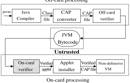
It can be seen that bytecode verification plays a critical part in the security of Java card. The problem resulted from the unreliable environment can be surmounted, if the bytecode verifier is transferred from off-card to on-card. Subsequently the security of the Java card will be improved definitely. However, it is very difficult to implement this verification process on Java card due to the limitation of the smart card itself. Figure 1 shows the utopian process of Java bytecode verification. After the on-card verifier is inserted into the whole process, the off-card verifier can be kept or removed from the schema according to the concrete verification algorithm.
Off-card processing
On-card processing
javac Java
Compiler
CAP converter
Off-card verifier Class
file
CAP file
JVM Bytecode
Verified applet
Verified CAP file On-card
verifier
Applet installer
Non-defensive VM Untrusted
Figure 1. Utopian bytecode verification schema.
II. RELATEDWORKS
A. Bytecode Verifier from SUN
It is necessary to review the traditional method of standard verification, as it was firstly implemented by SUN. This traditional bytecode verifier is based on a stack structure, where all the relevant local variables are stored. The traditional Java card verification interprets each method constituting the applet in an abstract way, aiming to check the control flow and data flow statistically so that they will not cause any error, for example, overflow or underflow of the stack, incorrect type of variable etc. This algorithm is called type
deduction, which is described in Leroy’s paper [3] in detail.
The algorithm of traditional bytecode verification, launched by Sun and developed by Gosling and Yellin, can be roughly described as follows. The verifier consists of a group of type stacks and a corresponding group of local variable arrays. When processing linear codes (without any branch or exceptional processing), the verifier will process each instruction in order. That is, it checks whether the entry is sufficient for or match each instruction. While processing codes with branches, it respectively takes folks and joins into account, and employs a data structure called “dictionary”, which consists of the stacks and local variable types of each corresponding branch or exceptional processing program point. When a branch instruction is analyzed, the branch type stored in the corresponding dictionary must be changed. That is, it is decided by the previous type in the dictionary and the Least Upper Bound, LUB for short, deducted from this instruction. Once the dictionary entry is changed, the corresponding instruction and the succeeding ones must be reanalyzed until a proper status is achieved. It can be calculated that the time complexity of this algorithm is O(S4), where S stands for the number of instructions of the verified program, and the space complexity is (3S+3N +3)×B, where S stands for the maximum stack space, N for the number of local variables in the method, and B for the number of different branches, given 3 bytes are needed to store each type.
B. Resource Limitation
From the above analysis of the traditional algorithm, it can be concluded that the Java Card Virtual Machine (JCVM) will mainly face the problem of limitation on the resource, which includes two aspects, namely hardware stress and limited memory space, when we attempt to transfer the off-card verifier to an on-card one. On a typical Java card, the RAM space is about 3k-6k, the EEPROM space about 16k-256k, and the CPU 16 or 32 bits. Based on the above discussed space complexity (3S + 3N + 3)×B for the algorithm of traditional bytecode verification, about 3150 bytes are needed for the to-be-stored dictionary structure in order to process a moderately complicate bytecode verification, given S = 5, N = 15, and B = 50. For the present Java card, it is impossible to allocate so many memory space of RAM to support the implementation of this algorithm. In addition, linear increase of the number of branches B in the program will probably lead to linear or even exponential rise on the memory space of dictionary in the algorithm, almost making the bytecode verification on Java card an impossible task.
All the above mentioned problems make it impossible to successfully implement this kind of traditional bytecode verification on Java card without any modification to it.
C. On-card Solutions Review
To solve the problems above, many researchers have made great efforts in the bytecode verification on Java card, as summarized below.
A Digital Signature method [3] uses the digital signature of a trusted third party, thus “omitting” the bytecode verification process on Java card. Though not relating to the narrowly defined verification, this method does not apply to those cases, where there is no trusted third party, for example, an offline one. Lightweight algorithm [5] processes all branches at the off-card stage of verification, and puts additional information into the bytecode. Then the instruction processed at the on-card stage of verification will become a linear one, because there is no branch, thus reducing the RAM space required by the verifier. However, the volume of bytecode will greatly increase (approximately by 50%) due to the additional information attached at off-card stage. Xavier Leroy [4] attempts to make semantic translation at the off-card stage of verification, so as to unify all instructions. While verifying the data structure, keep the stacks empty both in the beginning and at the end of processing, thus lowering the space complexity. This algorithm contains less additional information than the lightweight algorithm [5] (by approximately 2%). However, this algorithm can not check the initialization of local variables dynamically. Cinzia Bernardeschi [10] described a dynamic algorithm, which processes all branches in the control flow graph of the program, and deletes data in the stack after processing a branch structure before analyzing the following one. The maximum space complexity of this algorithm depends on the verification unit with the most branches in the program. PCC method [9] uses NVM to store the data structures corresponding to the bytecode verification, and this method proves to be practical in experiment. However, it takes much more time than the traditional algorithm as the writing operation of NVM is much slower than that of RAM, though this method does not present any problem with the storage space. An improved PCC method [2] differs from PCC in that a soft cache severs to try to put the bytecode verification into RAM, thus saving more time by the virtue of the quick speed of accessing RAM. But no reasonable cache scheduling algorithm is proposed in this method.
III. LOGICALFLOWGRAPHBASEDBYTECODE
VERIFIER
In response to the above-mentioned problems, this article presents a verifier based on the Logical Flow Graph (LFG), together with a corresponding cache scheduling algorithm. The LFG based bytecode verifier proposed in this article is to use NVM as the main memory, storing data types and relevant dictionary, and at the same time employs a part of RAM space as the
cache. To solve the problem that it takes long time for NVM to complete writing or erasing operation, this verifier adopts an improved non stressing type encoding method and provides a corresponding cache scheduling policy. In this way, it is possible to build an on-card verifier to execute bytecode verification.
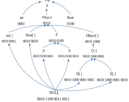
A. Improvement on Non Stressing Type Encoding With the consideration on the performance of NVM on smart card, this article attempts to improve the non stressing type encoding method proposed by Damien [2], and applies it in our proposed on-card verifier.
In traditional bytecode verification, the data structure of dictionary occupies a very large storage space in the whole verification process. To ease the space stress, we suggest storing this data structure in NVM.
Since it takes quite long time for NVM to complete reading and erasing/writing, it is necessary to minimize the data processing in cache. As the whole process of bytecode verification is type deduction, when processing complex branches, for example, when two branches converge on one instruction node, LUB can be available through a type comparison (“and” logic) between the corresponding types on the two branches. In terms of hardware, this type comparison shows that this processing process involves a large volume of data storage processing via cache, and it also relates to the operation of “and” logic, which will slow down the whole bytecode verification.
Top 0
int 0001
Object 0010
float 0100
int[ ] 0010 0001
float[ ] 0010 0010
C 0010 0100
Object[ ] 0010 1000
D 0010 0100 0001
E 0010 0100 0010
C[ ] 0010 1000 0001
D[ ] 0010 1000 0001 0001
E[ ] 0010 1000 0001 0010
NULL 0010 1100 0011 0011
Figure 2. Improved non stressing type encoding
The non stressing encoding proposed by Damien sets type encoding according to the type lattice, so that each type corresponds to a group of Boolean data. Since it takes less time for NVM to complete the writing operation than the erasing operation, we can change a certain bit position from 0 to 1 when several types are combined as one in the lattice, thus obtaining an improved encoding mode.
is necessary to get LUB of two types. For example, to get the LUB of D and E, just keep the first 8 bit positions that are the same for D and E. In this way, the “and” operation in hardware can complete type deduction by abandoning some data. With the cache scheduling policy, which will be described later, this improved type encoding mode is advantageous in that it is only necessary to record the length of the corresponding data type when the data in cache are written back into NVM, which saves the time of writing or erasing operation in NVM, thus reducing time for the whole verification process. Therefore, the improved non stressing type encoding can be well applied in bytecode verification on Java card.
B. Logical Flow Graph
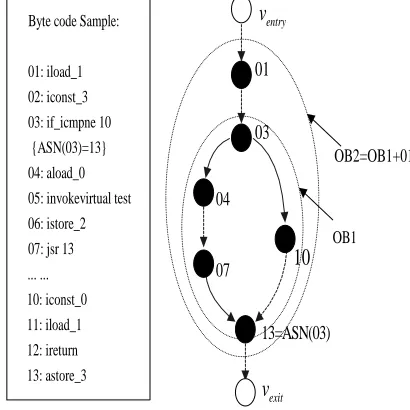
In our proposed bytecode verifier, a cache scheduling policy is used to solve the limited resource problem when doing bytecode verification based on Logical Flow Graph, LFG for short. Figure 3 shows a simple example of bytecode and the corresponding LFG.
entry
v
exit
v
Byte code Sample:
01: iload_1 02: iconst_3 03: if_icmpne 10 {ASN(03)=13} 04: aload_0 05: invokevirtual test 06: istore_2 07: jsr 13 ... ... 10: iconst_0 11: iload_1 12: ireturn 13: astore_3
13=ASN(03)
OB2=OB1+01
OB1
01
03
04
07
10
Figure 3. Bytecode example and corresponding LFG
Definition 1: LFG (Logical Flow Graph)
If a graph G is a logical flow graph, then it conforms to the following two conditions:
G is a directed graph, where the number of directed paths is greater than 1 ( P G
( )
≥1) and the number of nodes is greater than 3 (V G( ) ≥3); There are only one entry nodeu, the in-degree of which is zero (D uin( )=0), and only one exit nodev, the out-degree of which is zero as well (Dout( )v =0).The process of bytecode verification can be imaged as a LFG, where any nodeu, except for the entry node and the exit one, can be subdivided into a new graph. When all the nodes in LFG can not be subdivided any more, every node in LFG stands for a VM instruction Iu and every edge E u v( , )the dependency between instruction
u
I andIv.
Definition 2: MN (Master Node) and SN (Slave Node)
Supposedu v, ∈V LFG( ), if direct path P u v( , ) exists, then u is the MN of v and v is the SN of u. Specially, whene E LFG∈ ( ) and e=
{
E u v u v V LFG( , )| , ∈ ( )}
, u is the DMN of v, and v the DSN of u. Otherwise, u is the indirect MN, and v the indirect SN ofu. If v is the SN of u and the distance between them is longer than that between any other SN of u andu, u is the associated MN ofv, denoted asu=AMN v( ) , when Dout( )
u ≥2andDin
( )
v ≥2. At the same time, v is the associated SN of u, expressed as v=ASN u( ).Definition 3: OB (Operation Block)
Let u v, ∈V LFG( ) , if path set
( ) {
}
P u v, = P u vi( , ) | 1≤ ≤i n stands for all the possible
directed paths from u to v , then
( )
w{
w | 1j , wj ( , )}
V = ≤ ≤j m ¨ P u v is the set of all
the nodes located on P
( )
u v, , where wj¨ P u v( , )meansthat wj is located on P u v( , ) .
Furthermore, E e
( ) {
= ek | 1≤ ≤k q w, k¨ P u v( , )}
stands for the set of edges located onP( )
u v, . If vis the associated SN ofu , namelyv=ASN u( ) , then graph( ) ( )
{
,}
G= V w E e is an OB . Supposed that ,
s f
OB OB ∈LFG andOBs ⊂OBf, if a nodeOBt, which satisfies OBs ⊂OBt ⊂OBf can not be found inLFG ,
f
OB is the minimal envelope graph of OBs, represented
as OBf =MEG OB
(
s)
.When applied to bytecode verification, an OB in fact includes all the nodes which have the same entry and the same exit nodes, which can be considered as a basic verification and cache unit after combined with the other linear bytecode nodes or not.
C. Bytecode Verification Based on Cache Scheduling Policy
In addition to the non stressing type encoding method, a cache scheduling policy based on LFG is necessary to copy some data from NVM to RAM during bytecode verification, and then to substitute the data in RAM through scheduling cache, thus enabling the verifying instruction to extract data from RAM as more as possible.
Before describing the detailed verification process, it should be helpful to define some necessary functions, namely abstract interpreters (AI), which are based on LFG and play an important role in the process. Every AI includes a state, represented as i S, , where i is the value of the program counter and S is the current state of registers and operand stack. Definetype i
( )
to return the label corresponding to the instructioni , target i( )
to return the targets of instructioni, succ i( )
to return the( )
outst i to denote the function of the standard verifier
that generates the after-state of instructioni. Specially, there are two other functions regarding cache scheduling should be defined. One is writecache S
( )
, which represents that the current state S and the stack will be written into the cache when the instruction i does not hit the data in the cache, which is substituted according to the FIFO (First In, First Out) policy. Otherwise, if instruction i hit the data in the cache, the verification will be done in this cache. The other is writeback S( )
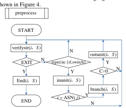
, which represents that the verifier will write the current state and the stack back to the NVM, when the current instruction is verified. Based on these definitions, the detailed bytecode verification process is described below.Step 1.initialization
All the control nodes corresponding to instructions with “if” or “switch” are analyzed according to the structure of LFG, to search the ASN of every node. The additional message indicating the positions of these nodes and the number of branches for each verification unit will be stored in the dictionary structure.
Step 2.verifystr
The instruction i will be verified as the traditional way and the instruction j is predecessor ofi, if it is not a control node or an ASN. If the instruction i does not hit the data in the cache, the data structure corresponding to instruction i will be put in the RAM, and the dictionary
corresponding to instruction i in the cache. The
state ,i S is transferred to〈succ i outst i S( ), ( , )〉. This step can be described as below.
( )
,
={
( ),
,
( ),
( , )
|
( ),
( ) {if, switch}}
verifystr i S
writecache S
i S
succ i outst i S
i
ASN j
type i
〈 〉 → 〈
〉
≠
∉
Step 3.inunit
When the control node (instructions with “if” and “switch”) is verified, the verifier finds the ASN corresponding to it. Then the NVM puts the instruction and the related stack in the RAM. The dictionary corresponding to the instruction is written in the Cache including the present state S to the ASN (if the space of the Cache is not large enough, the size of the data which is written in the Cache is equal to the size of the Cache). Then, verify them. The state <i S, > is transferred to <target( ), outst(i I, S)>. This step can be described as below:
min{ ( ), }
inunit(
)={
(
),
,
target( ),
( , )
|
ASN( ),
( ) {if , switch} }
ipd j i N
i S
writecache S,S
i S
i outst i S
i
j type i
+
〈 〉 →〈
〉
≠
∈
,
Step 4.outunit
When the ASN is verified, the verifier judges whether all the branches is verified (C is equal to 0 or not). If yes, all the control node-related node data, which can be substituted in the following verification, will be released from the RAM. The related structure of the current instruction is put into the RAM to be verified and the dictionary is put into the Cache. The state i S, is transferred to <succ( ),outst( , )>i I S and the state
outst( , ) i S is rewritten into the NVM. This process can be stated as below.
outunit( )={ ( ), ,
( ), ( , ), ( ( , )
| ASN( ), ( ) {if, switch}, 0 } i S writecache S i S
succ i outst i S writeback outst i S
i j type i c
〈 〉 →
〈 〉
= ∉ =
,
Step5.branch
When the ASN is verified, it should be determined whether all the branches are verified (C is equal to 0 or not). If no, the writecache( , )i S is executed. When the instruction is not hit, the verifier substitutes the data in Cache and verifies it in the RAM. The state< , >i S is transferred to <target( ),outst( , )>j i S . Then the verification jumps to the next branch.
branch(
)={
( ),
,
target( ),
( , ) ,
|
ASN( ),
( ) {if, switch},
0 }
i S
writecache S
i S
j outst i S c
i
j type i
c
〈 〉 →〈
〉 −−
=
∉
≠
,
Step6.end
When the exit node EXIT is verified, the verification process finishes. The state “success” stands for the verification is completed successfully.
end(i,S)={ ,〈i S〉 →success | i=EXIT } The flow chart of this Cache scheduling algorithm is as shown in Figure 4.
inunit(i,S)
outunit(i,S) verifystr(i,S)
branch(i,S) preprocess
START
EXIT
END
∈ type(i) {if,switch}
C=0 N
N
N
N
Y Y
Y
Y ASN( )
i= j
End(i,S)
Figure 4. Flow chart of Cache scheduling algorithm
time advantage of RAM and the space advantage of NVM.
IV. RESULTANDANALYSIS
A. Compare to the traditional algorithm
Because the traditional algorithm puts all the data in RAM, the space complexity is (3S+3N +3) ×B. In our algorithm, the space complexity on RAM depends on the part with most branches in the LFG. Assume C as the maximum number of branches between the total control nodes and the corresponding ASN, then the corresponding space complexity of RAM will be (3S + 3N + 3) × C, C < B.
B. Compare to the improved PCC algorithm
The verification process can be described and analyzed in detail, with the following bytecodes in Figure 3 as an example.
In the beginning, the verification program searches all control nodes, indicated by 3 in the figure, and the corresponding ASN (3) =10. The number of branches of a verification unit is recorded as C=2.Verification begins from where START is indicated, and the dictionary is empty. The corresponding data in RAM are null, and instructions are scheduled in order from NVM and stored in the corresponding status stacks. When verification comes to the first control instruction, which is 03: if_icmpne10, the instruction enters an OB, and the corresponding successor status is written into RAM until
it reaches 13: astore_3. The verifier reads out corresponding status from RAM and verifies this verification unit.
When verification reaches 13 for the first time, C=1, and not all the branches have been verified. Then the verification program returns to the entry control node 3 to continue verification until it reaches the ASN of the control node. After the analysis, the program saves the entry status and input status into Cache, and all data of this OB in RAM can be substituted in the following verification. The verification program implements operation in this way until it reaches the node indicated by “END”, then verification finishes.
The following is an analysis of the above presented bytecodes. Assume 8 for the number of instruction stack structures that can be stored in RAM. Based on the algorithm of improved PCC [2], relevant data are called every time by the program flow. When verification starts from node 1, relevant information of nodes 1-8 will be written into Cache, and both verification nodes 2 and 3 are hit. When node 10 is not hit upon verification, information of this node will be written into Cache and substitute node 1 based on the principle of “First in, first out”. Similarly, if none of the nodes 11, 12, 13, 3, 4, 5, 6, 7 and 13 is hit upon verification, the substituted nodes will be respectively 2, 3, 4, 5, 6, 7, 8, 10 and 11. See Table 1 for the hit status.
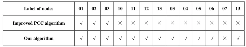
Table 1 is based on the above-analyzed Improved PCC algorithm and the substitution policy introduced in this article.
TABLE I.
COMPARISON BETWEEN IMPROVED PCC ALGORITHM AND THE POLICY MENTIONED IN THIS ARTICLE (√ STANDS FOR “HIT” WHILE × FOR “NOT HIT”)
Label of nodes 01 02 03 10 11 12 13 03 04 05 06 07 13
Improved PCC algorithm √ √ √ × × × × × × × × × ×
Our algorithm √ √ √ √ √ √ √ √ √ √ √ × √
According to the data in the table, obviously the hit rate is approximately 23.08% for improved PCC algorithm, while it is approximately 92.31% for the scheduling algorithm introduced in this article, which means the hit rate can be greatly improved with the Cache scheduling policy introduced in this article.
It is normal and reasonable for improvement of the hit rate since the scheduling algorithm in this article follows the LFG, that is, the scheduling follows the verification process. It is improved on the complicated scheduling algorithm. However, since this scheduling algorithm process is similar to the flow process, the program can guarantee its implementation without occupying large extra memory space while implementing the Cache scheduling policy during the verification process.
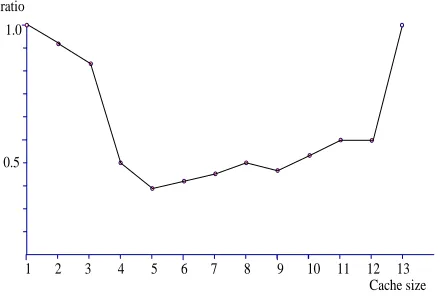
A comparison of the time for substitution between the algorithm introduced in this article and that with the algorithm of improved PCC shall be given for the Cache of different lengths because the time is affected by the
Cache and NVM, the more there will be data verified in Cache.
Therefore, the difference between algorithms will become insignificant.
The time for substitution 13 T
1 T
1 2 3 4 5 6 7 8 9 10 11 12 13 Cache size The algorithm in this article
Improved PPC algorithm
Figure 5. The time for substitution between the algorithm introduced in this article and that with the algorithm of improved PCC for Cache
of different length
1 2 3 4 5 6 7 8 9 10 11 12 13 0.5
1.0 ratio
Cache size
Figure 6. Ratio of time with the algorithm introduced in this article to that with the algorithm of improved PCC
As for the time of the algorithm, the whole verification process consumes the traditional verification time plus the time for the Cache scheduling algorithm, with the process of the Cache scheduling algorithm taken into account. The algorithm introduced in this article try to avoid the writing and reading problems of NVM by converting the writing and erasing operations of NVM into reading operation in the improved non stressing encoding mode, thus removing the bottleneck in the time of reading and writing with NVM.
For the operation of writing into RAM necessary the scheduling algorithm, the whole verification process consumes the traditional verification time and the time for the Cache scheduling algorithm, based on the analysis of the time complexity, and as the processor reads and accesses data in a short time, the time complexity O(S) of the added verification time △T with the Cache scheduling algorithm is completely acceptable, compared with the time complexity of the traditional verification algorithm O(S4).
In addition, it will not take more than 0.2 for RAM to write in a bit data. Based on such time complexity, it can be guaranteed that the verification process can be completed within the time acceptable to users with enough verification space as mentioned above for the whole verification process.
C. Guarantee of the Algorithm Correctness
The following aspects can guarantee correctness of the verification program. First, the basic principle of verification is the algorithm of traditional verification, which guarantees that the verification has been testified and proved correct in terms of algorithm. Second, the memory capacity of NVM guarantees the algorithm of traditional verification, thus avoiding verification failure caused by any fault as a result of insufficient memory capacity during the verification process. Last, the Cache scheduling policy and the improved non stressing encoding guarantee reliable verification in terms of time.
Based on the comparison between the above-mentioned algorithm of improved PCC and the analysis of time complexity, we can draw a conclusion that this scheduling algorithm is better for the bytecode verification on Java card.
V. CONCLUSION
This article designs a mode of bytecode verification on Java card based on the Cache scheduling algorithm. In this mode, the bytecode verification can be implemented completely on Java card through Cache, without being restricted by limitation of the Java card itself. Another reason for preference of this scheduling algorithm is that any preprocessing is unnecessary for the bytecode, that is, any bytecode, which is correct yet not pre-processed, will not been refused by the verifier. Through data scheduling of NVM and RAM, this algorithm realizes a perfect verification process based on traditional bytecode verification, featuring strong transportability and feasibility.
ACKNOWLEDGMENT
Instructions and supervisions from Prof. Xinfang Zhang, constructive suggestions from Xinlong Ma and Mingwei Fang, and collaborations of Tongyang Wang and Jun-jun Wu are gratefully acknowledged.
REFERENCES
[1] Zhiqun Chen. Java Card Technology for Smart Cards: Architecture and Programmer’s Guide. Addison Wesley Longman Publishing co., Inc., 2000.
[2] Damien Deville. Building an “impossible” verifier on a Java Card. In USENIX Workshop on Industrial Experiences with Systems Software(WIESS’02), 2002. [3] X.Leroy. Java bytecode verification: algorithms and
formalizations. Journal on automated reasoning, 30, 2003. [4] X.Leroy. Bytecode verification on Java Smart card.
Software Practice & Experience, 32:319-340, 2002. [5] Rose E, Rose K. Lightweight bytecode verification. In
[6] Joachim Posegga and Harad Vogt. Java bytecode verification using model checking. In 26th symposium Principles of Programming Languages, pages 70-78. ACM Press, 2002.
[7] Raymie Stata and Martín Abadi. A Type system for Java bytecode subroutines. ACM Transactions on Programming Languages and System, 21(1): 90-137, 1999.
[8] Virtual Machine Specification. Java Card TM Platform, Version 2.2.2. Sun Microsystems, Inc, 2006.
[9] George C.Necula. Proof-carrying code. In 24th symposium Principles of programming Language, pages 106-119. ACM Press, 1997.
[10]C. Bernardeschi, L. Martini, and P. Masci. Java bytecode verification with dynamic structures. International Conference on Software Engineering and Applications (SEA), Cambridge, MA, USA, 2004.
Tongyang Wang(1963-), male, Wuhan Hubei, Institute of Information & System Technology, Huazhong Univ. of Sci & Tech. associate professor, Ph.D, Research in Embedded System, CAD.
Pengfei Yu(1981-), male, Chibi Hubei, Institute of Information & System Technology, Huazhong Univ. of Sci & Tech. Ph.D Candidate, Research in Embedded System, Trusted Computing, Secured Portable Storage, Information Security.