Prototype Design and Synthesis of Cluster
MPSoC Architecture for Multiple Applications
Da Li
School of Electronics and Information Engineering, Xi’an Jiaotong University, Xi’an, China Email: [email protected]
Yibin Hou, Zhangqin Huang and Chunhua Xiao Embeded System and Software Institute, BJUT,Beijing, China Email: {yhou,zhuang}@bjut.edu.cn, [email protected].
Abstract—Modern embedded devices require high performances such as computing, throughput and power consumption. Multiprocessor System-on-Chip (MPSoC) is a promising solution to meet the requirements. And the Network-on-Chip (NoC) is used as the interconnection of MPSoC. Whereas it brings more challenge on application programming and fast design exploration of software and hardware implements automatically.
In this paper we propose a cluster MPSoC architecture, which adopts hybrid interconnection of processor clusters and NoC. And we present a design automation and synthesis methodology to generate MPSoCs in a system-level way for multiple application use-cases. And it merges them onto a minimal hardware architecture of resources. The desired MPSoC design is generated with short design time, making it suited for fast design exploration for MPSoC development. The proposed design flow is implemented into a tool for Xilinx FPGAs. The experiments results illuminate that our design methodology is a convenient approach to generate the MPSoC design for multiple use-cases.
Index Terms—cluster MPSoC systems, multiple use-cases, colored timed Petri net, design exploration
I. INTRODUCTION
New applications for embedded systems demand complex multiprocessor designs to meet the constraints such as real-time deadline, energy consumption and resource usage ratio. The Multiprocessor System-on-Chip (MPSoC) is proposed as a high performance architecture for such problems [1], for the requirements of higher computing performance, good flexibility, lower power consumption, but there are many design challenges for such complex multiprocessor systems. One of the key design challenges is the automated design space exploration (ADSE) of such MPSoC systems, to allow fast exploration of system hardware and software implementations with accurate performance design and evaluation [2].
Many such potential use-cases in the embedded devices is leading to a design shift towards developing systems in software and programmable hardware, and a single hardware configuration may not suit for large number of use-cases. So in this paper we present a solution to provide a systematic design methodology that generates high level models for the desired multiple use-cases, to generate a merged design for the use-cases. The approach merges use-cases onto a hardware configuration such that multiple use-cases can be supported in MPSoC system with varieties of performance requirements.
We also estimate the performance of mapping design, and use decentralized computational grads of fuzzy system to control decision with characteristics of system state description. This fuzzy approach can find well-performing tradeoff policies for performance characteristics. Results of a case-study with multiple applications are also presented. And we compare the results of analysis with FPGA implementation.
The rest of this paper is organized as follows. Section II reviews the related work for system design and synthesis methodology for multiprocessor systems. Section III introduces the CTPN graphs. Section IV describes our approach of mapping multiple use-cases onto MPSoC. Section V presents the results of experiments obtained by our design methodology. Section VI concludes the article and gives directions for future work.
II. RELATED WORK
How to map the application to the architecture is one of key design problems, and it has been widely studied in literature. Model of Computation (MoC) is essentially a general way of describing system behavior in an abstract, conceptual form and as such enables representation of system requirements and constraints on a high level. Dataflow models are often used for modeling DSP applications and for designing concurrent stream applications [6]. ESPAM [7] uses Kahn process networks (KPNs) for application specification, but the KPN is limited to a single application and completely distributed over individual processes, which is difficult to achieve an efficient and practical realization. MAMPS [8-9] uses Manuscript received December15, 2011; revised April 12, 2012;
accepted April 17, 2012.
synchronous dataflow (SDF) for applications specification, but it cannot capture the behaviors of competition and constraints on resources between applications. So the SDF is limited to independent applications. In our approach, we use Colored Timed Petri Net (CTPN) [10-11] to extend dataflow model in a high abstraction for the application specification instead. CTPN uses colored sets to present kinds of resources, and time labels to present the timing of processes, which are efficient to describe data stream and control between processes. CTPN can be viewed as a combination of process-oriented and state-oriented MoC. CTPN can get the dynamic behaviors of data transfer and states of resources. And further our approach creates a hierarchical CPN design to support multiple applications.
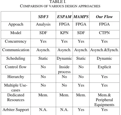
Table I shows estimates of various design approaches by various means. The first method SDF3 [12] is only able to predict performance of single applications. ESPAM does not support multiple applications. MAMPS is the closest to our approach, as it uses FPGA and supports multiple applications, but it is limited in memory resource and it does not support the control flow. Our flow supports multiple applications and different resources, and also provides quick results of application performances and realization on FPGA.
To be cost effective, SoCs are often programmable and integrate several different applications or use-cases. But the use-case concept is relatively new to MPSoCs. Murali [13] focuses on the communication infrastructure of MPSoC, in particular networks-on-chip (NoC). And the MAMPs is to design a common point-to-point connections for multiple use-cases. Our flow is mainly targeted towards hierarchical connections, which use both of NoC and processor clusters. The use-case is defined as a combination of some applications like a use-scenario [5], and more use-cases with new applications will emerge in front of us. The design methodology for multiple use-cases in embedded devices is essential to the research in the design automation, which allows designers to quickly generate MPSoC designs for various use-cases and to achieve the performances requirements, such as low costs, high computing performance. Our design methodology provides an approach for designers to study the performances of the use-cases and tune the architecture to achieve a better performance. Our target hardware platform is Xilinx FPGAs, and Xilinx provides a tool-chain as well to generate the designs, but the tool mostly aims at designing with architecture of one or two processors. So it is time consuming and error prone to generate MPSoC architecture by manual operations. In our flow MPSoC is automatically generated together with software for each processor.
III.CTPN AND PROBABILISTIC ANALYSIS
A. CTPN Specfication
In a typical CTPN, a transition represents a task execution. Tasks also need some input data or control and usually also produce some output, such data or information is referred to as tokens. Directed arcs
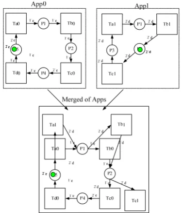
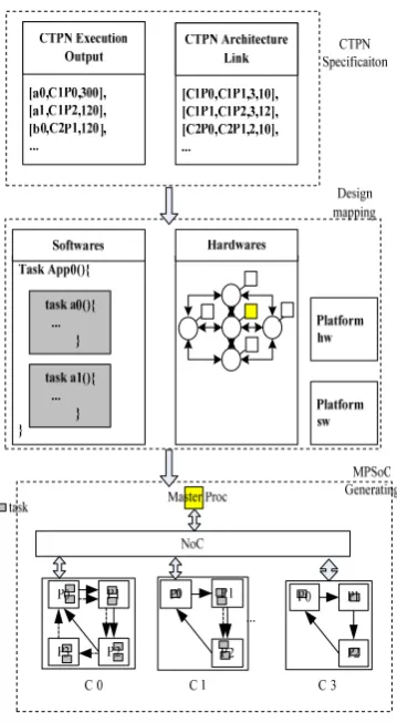
represent the dependency of tasks. Different kinds of data stream may be defined as colored tokens to distinguish between each other. Data buffers may be modeled as tokens on a back flow on places. In such case, the number of tokens on the place indicates the buffer size available. When a transition fires, the input data buffer size reduces and the output data buffer size increases. Fig.1 shows an overview of CTPN of multiple applications. It merges App0 and App1 into a CTPN model, in which each application has its own dataflow graph. The two applications share the data places and they may be dependent or independent, presented by colored tokens. The data flows are in a concurrent running environment and time tags are appended to these tokens, so the execution time of tasks and resources usage on the processing core are also specified. It is useful for present the constraints of multiple applications running on the MPSoC, and research on the contention of resources (kinds of resources include not only shared memory, and also computing IP cores, interface IP cores) and the dynamic execution of applications.
Resources are always a constraint in an FPGA device and the applications are represented by a Petri net of several transitions and places, but as the number of use-cases to be supported increases, the scale of the multiple use-cases CTPN models increases as well. It is inefficient for simulation and analysis and mapping onto FPGA devices. So we abstract CTPN model of application into a hierarchical CTPN block, as shown in Fig.2. Use-case is a combination of some applications, which can be active simultaneously. Applications are converted into execution blocks, in which tasks of the application are described as some elements. With the relative rules, all applications can be presented into a top CTPN. CTPN system use job set to present each use-case. Jobs can run concurrently in the hierarchical CTPN, while tasks execution and resources usage are also marked. Using some scheduling algorithms, the model runs in
TABLE I.
COMPARISON OF VARIOUS DESIGN APPROACHES
SDF3 ESPAM MAMPS Our Flow
Appoach Analysis FPGA FPGA FPGA
Model SDF KPN SDF CTPN
Concurrency Yes Yes Yes Yes
Communication Asynch. Asynch. Asynch. Asynch.&Synch.
Scheduling Static Dynamic Static Dynamic
Control flow No Inside process
No Explicit
Hierarchy No No No Yes
Multiple Use-cases
No No Yes Yes
Dedicated Resources
Mem. Mem. Mem. Mem.&
Peripheral Equipments
Figure 1. Example of a CTPN of multiple applications.
Figure 2. Hierarchical CTPN.
CPNTools[16] and generate the applications specification for hardware architecture. For example, a tuple <TaskID, ProcID, ExecTime> represents the task assigned onto the processor and its execution time; and also usages of processor, memory, and modules ( computing core or interface core). The number of tokens also may illuminate capacity of required resources.
When multiple applications run concurrently, they often compete for resources. A probabilistic computing model can be used to predict the contention. The response time of task can be denoted as:tresp=texec+twait.The twait is
the time that task spends on waiting for available resources in contention. And the tresp indicates how long
it takes to process the task after it arrives at the processor node. But for use-case of applications is not always known at design-time, it is not possible to exactly get the waiting time. So we use a probabilistic approach to estimate it. In the example CTPN of applications, assuming that execution dataflow of App0 is as
0(80) 0(40) 0(40) 2 0(40)
Ta →Tb →Tc → Td ; and for
App1,it is2Ta1(40)→Tb1(80)→Tc1(80). Here task Ta0
runs 1 time and spends 100 units time in a period. Ta0
and Ta1 are mapping on a processor Proc0. Ta0 is active
for t Tae( 0) * (r Ta0)in Per A( 0) time units, and the
probability of Proc0 is used by Ta0on average equals
0 0 0
( )* ( ) / ( )
e
t Ta r Ta Per A . And Ta1 can arrive at random
time, its waiting time can be a variable from [0, (t Tae 0)].
For the probability density function p x( ) of Ta1
waiting forTa0can be defined as follows, similar as that
in [14]:
0 0
0 0 0
w 0 0
1 ( ) ( ), 0
( ) ( ) / ( ), 0 ( )
( ), ( )
e a w a
e a e a e a
a e a
P T P T x
p x P T t T x t T
P T x t T
− − =
⎧ ⎪
=⎨ < <
⎪ =
⎩
(1)
As shown inp x( )it indicates the probability of
1
Ta distribution with Ta0states. And the corresponding
expected wait time can be computed.
( 0) 1
0
0
0 0
( ) ( ) ( )
( )
( )( ( ))
2 te Ta wait a
e a
e a w a
t T E x xp x dx
P T
t T P T
= =
= +
∫
(2)
For multiple applications mapping onto MPSoC, the system total wait time can be the overall tasks wait time on each processor sum up:
_ ( )
n
wait wait j
n m
t total=
∑∑
t T (3)With new estimated wait time, the system’s response time should be updated. Applying this approach in above example and for iterative execution of system, it will get stable after several loops. The corresponding period of applications in these loops should be 286, 290, 291, and it will be stay at 291. And the system worst case wait time
should be _ ( )
n
wait exec j
n m
t worst=
∑∑
t T , then WCRT is 480.But in actual the period will be 240 for best-case and 320 for worst-case. WCRT is over-estimated by 50%. And if we use a maximum distribution probability of wait time. So twait_ max(Ta1)=Emax( )x =t Te( a0)( (P Te a0)+P Tw( a0)), it
may be viewed as a conservative up-bound estimate. Its value should be 324, which is a little more than actual worst case.
B. Fuzzy-system-based Scheduling Approach
(1) (1) 1 1
(γ δ, ) (2) (2) 1 1
(γ δ, ) (1( ),1( )) Nf Nf γ δ 1 R 2 R Nf R 1
R R2 RNf
( ) D Y x
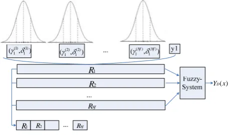
Figure 3. Fuzzy-system-based scheduling approach
IF queue is long and task highly parallel THEN decline task
IF queue is empty and task not parallel THEN accept task
M M M
A complete rule base constitutes the core of rule system. The current system will be checked by the rules while new applications are added into the system. Generally the TSK model consists of Nf IF-THEN
rulesRisuch that:
(1) ( )
1 1 1
0 1 1
: IF is and and is
THEN = f
Nf Nf Nf N
Ri x g x g
yi bi bi x bi x
=
+ + +
L L
Here xj are inputs of rules states, and yi is the
nonlinear local output of decision state. g( )f
i is the input fuzzy set that describes the membership for a feature f . Thus system state is denoted by Nf features. The degree
of membership is function value with input fuzzy set characterized. And the overall output of the system can be computed as:
( ) ( ) ( ) , ( ) ( ) ( ) f D N
x y h
x
x h
y =∑φφ φ x = ∧g x
∑
Where ( )φ x is the degree of membership of rule for the inputx, therefore the output value of TSK model is computed by the weighted rule’s recommendation over all. Fig.3 shows the rules encoding by the membership functions, each feature can be modeled by a ( , )γ δ characteristic function. The TSK model can be simplified with binary decisions. Thus the whole rule base is encoded by concatenation of single rules. A rule base of
n rules is described by a set of l=n n(2 +1) parameters. Therefore the scheduling optimization is to find suitable parameter settings for the rules in order to get well-performing performance of applications.
For current system state we rely on different features that will constitute the conditional part of rules. In order to cover comprehensive system information with a single feature, we consider the Normalized Applications Period (NAP) as a feature:
( ) ( ) n Per An NAP WCRT An
= . (4)
it indicates the performance of each application and reflects the satisfaction of its execution.
The second feature is the Normalized Resources Requirements (NRR): ( ) ( ) n NRr An NRR NRa An
= . (5)
It is the ratio of Application resources requirements and the maximum number of available resources.
And also we consider the workload of processor nodes, the Normalized Processor Usage (NPU):
1
( , ) max( ( ))
m A m
m
NPU texc T P
Per A
=
∑
. (6)it indicates the total execution time of applications on processor nodes.
We use fuzzy sets to describe the priority levels of tasks, as shown in (7). S(x) gives the fuzzy description of characteristic x, and uAi(x) is the membership of x
belongs to expression Ai.
1
1 1
( )
( )
( )
,
( )
1
n
A An
Ai
n i
u
x
u
x
S x
u
x
A
A
==
+…+
∑
=
(7)
It is used for describing NAP, NRR, NPU and other parameters that computed in TSK model. Thus the NAP can be classified by Ai. such as
“shortest”, ”short”, ”medium”, ”long”, ”longest” and etc. and these fuzzy memberships of task, can be loaded into the fuzzy system, to compute the composite target function of task priority.
In the policy of processor selection, we should consider the relationships between the feasible time of tasks, available time of resources and available time of processors, and select the appropriate processor in available processor subsets to reduce the schedule time length of task sets and improve processor utilization.
IVGENERATING MPSOCSYSTEM
A. Design of Hardware Architecture
The NoC has been proposed as the future on chip interconnection. Whereas, NoCs brings more challenge on the parallel programming and synthesis. So we design a new cluster-based homogeneous MPSoC architecture. The processors are organized into clusters, in which processors are connected by fast FIFO links. These FIFO links remove the possible sources of contention that can limit performance and support multiple applications running concurrently better. For inter-clusters the system uses a simple NoC architecture composed by nodes of router, and implements the communication between nodes by passing messages.
Figure 4. MPSoC for multiple use-cases.
Figure 6. Architecture of MPSoC with NoC and Clusters
Figure 5. Merging design of multiple use-cases. on the FPGA, setting the MPSoC system on FPGA
processing the video data, and output the video multi-display onto a PC screen. And also pictures stored in the flash memory are used for JPEG encoding and decoding.
For obtaining better performance of the cluster, we adopt hierarchy communication architecture as shown in Fig.5. It means that each cluster is a node, and communicates with others through the NI interface. The NI provides a set of functional registers for controlling the packet transferring process, including Tx/Rx State Register, Tx/Rx Packet Length Register, Tx/Rx Packet ID Register, input and output buffers can be directly accessed by FSL link, which is implemented by FIFO. The on-chip router is the key of NoC design, it should implement the functions of routing, flow control, switching, arbitration, and buffering for the network communication. There are five input channels and five output channels in one router, and they are connected by a interconnection. This router adopts synchronized handshake protocol in flow control.
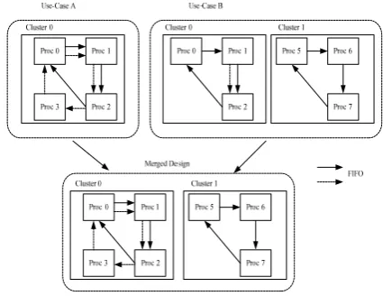
B. Merging Design for Multiple Use-cases
From these application specified descriptions, a multiprocessor system is generated. Each task is mapped on a separate processor node and each link mapped to a unique FIFO channel. Processors will be shared by these
tasks and the total number of processors corresponds to the maximum of tasks in an application. To avoid overload on some processors and deduce the inter-communication among processors, independent applications are mapped into different clusters by the fuzzy-system-based scheduling, on comprehensive estimation of applications and resources performances. In Cluster, the dataflow between processors are mapped into unique FIFO links, and different applications use their own communication as shown in Figure 5(d). The design supports the flow stream of pipe-line and also reduces the contention of communication channels.
With different use-cases, the hardware designs are usually different, so an entire new design has to be re-synthesized for multiple use-cases. Here we describe how we merge the designs for the use-cases into a hardware configuration in Fig.6. Tasks of applications are mapping onto processors in group of clusters, and the hardware of two use-cases is integrated with minimal hardware requirements to support both use-cases. The combined design can be seen as a superset of requirements of the two use-cases. The algorithm is to obtain the minimal superset of the hardware design requirements of all use-cases. It iterates over all use-cases to compute their individual resource requirements and generate the maximum needed for all use-cases.
Software generation is easier as compared to hardware. Applications program are partitioned into tasks by some benchmarks and are mapping into relative processors software. And also the communication functions of FIFO (such as readFIFO or writeFIFO) will be added into the processor software. The FIFO id needs to be consistent to that in hardware descriptions.
Figure 7. DSMAMPS flows
Figure 8. Period computed using iterative analysis architecture design. According to the specifications of
merged design, DSMAMPS generates the hardware and software files of FPGA system automatically, and also generates final executive bit file with Xilinx EDK synthesis commands.
V.EXPERIMENTS AND RESULTS
In this section, we present some results obtained for the iterative analysis as compared to simulation. The overall application throughput predicted is compared with the measured. And in our experiments, we generate 7 typical applications such as H.263 encoding and decoding, JPEG encoding and decoding, voice call and surf web, and also generate 10 use-cases.
A. Applications Period
In the experiments iterative analysis is used to compute the performance of all the applications, and the results of other techniques like the worst case and actual observed , and also the approximation exponential probability approach[14] are also presented. Fig.8 shows the results of iterative analysis with the varying iteration times for application D.
Its original period is 457. When running concurrently in the use-case of multiple applications, its execution period is 1243. The exponential approximation approach estimates it as 1601, while the worst-case is 3405. And the iterative approach gets a predicted period of 1320 for four iterations and 1258 for six iterations. We can see the
iterative approach get a closest estimate period and get stable after some iterations. And the final estimate is independent of the initial estimate, like original or worst-case estimates. That gives an efficient approach to estimate the period of applications.
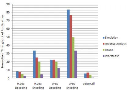
B. Applications Throughput
The throughputs results of such combinations are summarized in Table II. The results are compared with simulation. We observe that in general, the applications throughput measured on FPGAs is lower than simulation by about 6.7% (Average throughput variance of applications A0, A1and A2).This is because our simulation models do not take into account the system communication consumption of Clusters. That will make applications execution take somewhat longer than expected, hence it delays the start time of responded tasks and also reduces the throughput of system. However, we are dealing with the multiple use-cases, the contention of resources might cause some applications to wait for tokens, throughput of some applications is significantly lower. We can observe that in use-case U3 throughput of application A2 is lower than simulation 20.22%, and in another use-case U5 throughput of application A2 is lower than simulation 21.27%. In FPGA implement the communication overhead may affect the execution
TABLE II.
COMPARISON OF THROUGHPUT FOR DIFFERENT APPLICATIONS
OBTAINED ON FPGA WITH SIMULATION
App1 App2
Use-case Sim FPGA Var % Sim FPGA Var %
Figure 9. Comparison of throughput for applications
Figure 10. Performance of fuzzy-based approach
Figure 11. Results of video converting and picture processing performance of tasks, thereby delay the start of
successive tasks. Most of the applications get a less variance throughput from simulation, this illuminates that concurrent execution of multiple use-cases is more complex.
C. Mapping Multiple Applications
The real multiple applications pose some characters effecting performance prediction, such varying execution times of tasks and running times in a period. And further the number of tasks mapped onto processor nodes may vary significantly. Thus it is essential to optimal the scheduling of these tasks for a well-performing tradeoff of performance. Here we use the fuzzy-system-based scheduling approach in Section 4 to allocate the tasks. Fig.9 shows the comparison between the simulation and implement on FPGA. A couple of observations can be made from the graph. The throughput of applications increases in different proportions when executing concurrently while the throughput of JPEG encoding decreases 17% and that of voice call decreases 95%. This is affected by the number of tasks in application, and the resources contention of execution. Such as VLD of JPEG decoding is executed once per period and IQ of H.263 decoding is executed 594 times per period. This causes significant degradation in the performance. And the iterative analysis gets accurate estimates. And for optimal scheduling, our fuzzy-system-based approach gets a better workload and improvement of some applications in Fig. 10.
And the Fig.11 shows an example of our MPSoC design, which works on some real-time video converting such as scaling control and color filter, and also the picture processing of JPEG encoding and decoding. The input video is divided into two, one is for the right monitor to show, and another is transmitted into the XC5VLX110T FPGA board. We use the MPSoC on FPGA chip to complete the multiple applications, and output the videos and pictures onto the 4 screen windows of the left monitor.
D. Resources Requirements
Since the embedded device has limited resources, it is important to doing a design space exploration and computing the optimal resources requirements. We explore the tradeoff between buffer memory required and throughput obtained for multiple applications. Table III shows how the throughput of applications varies with numbers of tokens.
A couple of observations can be made from the table. When the number of tokens increased, the throughput also increases until reach an upper limit. When the application A2 is the only running application (setting initial tokens of other applications to 0), we can observe that its throughput increases almost linearly until 8 tokens, and it will get less increase after that. Further when multiple applications running concurrently, different initial tokens of A0 and A1 will worsens the performance of A2, but only until a certain point. It explains that the increasing initial tokens (assigned hardware resources size such as buffer or computing IP cores) will affect the
TABLE III.
COMPARISON OF THROUGHPUT WITH VARIES INITIAL TOKENS
Initial tokens Throughput
A0 A1 A2 A0 A1 A2
0 0 0 1 1 1 3 5
0 0 0 1 3 5 3 5
1 8 10
1 1 1 5 5
- - - 1.62 1.40 1.24 4.30 3.27
- - - 1.94 5.04 5.24 4.95 4.19
performance of multiple applications, but it will cause no change beyond a certain value. Increasing initial tokens for A0, A1 and A2 cause no change beyond 3, 5 and 8 separately. So it shows the required number of initial tokens for each application, with which we can assign appropriate resources for these applications. This analysis allows the designers to choose a desired performance tradeoff for the multiple applications execution.
E. DSE of MPSoC System
The time spent on exploration is an important aspect when estimating the performance of big designs. The MPSoC for multiple use-cases are designed both by-hand and by our tool. The results are shown in Table IV. For hardware and software generation, Xilinx toolset just supports single or two processors. Designers have to add the multiple processors and other IP components by-hand, and also connect them one by one. It is very time-consuming and error prone. Even for single application design it will take 12 minutes and 20 minutes separately, no matter the more complex design for multiple use-cases. In contrast, our design flow the total time of hardware and software generation for 5 use-cases is just 250 milliseconds.
Since with Xilinx tools the hardware synthesis step takes about 68 minutes and software synthesis step takes about 1.5 minutes, the entire DSE total time is about 103 minutes. For the multiple use-cases, it will take designers 1~2 days at least and more attention on the error correction of design. In our auto-design and synthesis flow, it takes about 68 minutes and 3 minutes for hardware and software synthesis, so the entire DSE for 5 use-cases is carried out in about 71 minutes. Contrast to Xilinx toolset, our auto-design methodology results in a speedup of 7.3 when generating a new merged hardware for each use-case. As often we can use a hardware design to support multiple use-cases, the hardware just needs to be synthesized once; with the number of use-cases increases, the cost of generating the hardware becomes more less for each use-case. This study is illustrating our design flow is useful and convenient for DSE of MPSoC system.
VI CONCLUSIONS
In this article we propose an auto-design flow to generate the Cluster MPSoC designs for multiple use-cases. Our approach takes the system-level description of
multiple use-cases in CTPN, and produces the corresponding MPSoC mapping specifications for use-cases. Our design flow allows simulation and analysis of throughput and resources requirements and other performances. It is convenient to study the tradeoff between performances and get a desired MPSoC architecture. And we present the approach to merge and partition use-cases into a minimal hardware design. And our design flow integrates auto-design and synthesis, which allows designers to generate the complex MPSoC design quickly, without much time consuming, and error prone.
The experiment with multiple application use-cases shows the prediction is close to the actual execution. Further, it takes four to six iterations for prediction converging and its final estimate is still accurate with varying initial points. The accuracy of prediction is validated with multiple applications implement on FPGA MPSoC system. And to find a mapping design of well-performing workload and performance of system, we present a fuzzy-system-based approach to decide the distribution of applications’ tasks by system state features. It allocates applications for good performance characteristics such as applications response time and resource utilization.
Further we would like to expend design objects, and develop more ways for kinds of SoC architectures, such as heterogeneous processors, irregular network interconnection. And we would also try parallel partition of applications to high speed requirement and try evolutionary learning process to the fuzzy system to optimize the rules base. And we would also try parallel partition of applications to high speed requirement and try arbiters to improve load-balancing between multiple applications.
ACKNOWLEDGMENT
This work was supported by the National Natural Science Foundation of China under Grant 60773186, and the Project of High-level Personnel Training of BJUT.
REFERENCES
[1] W. Wolf, “The future of multiprocessor systems-on-chips,” Proc. of 41st Annual Conf. on Design Automation, pp. 681-684, 2004
[2] T. Agerwala and S. Chatterijee, “Computer architecture: Challenges and opportunities for the next decade,” IEEE Micro, vol. 25, no. 3, pp. 58-69, 2005
[3] S. Dutta, R. Jensen and A. Rieckmann, “Viper: A
multiprocessor SOC for advanced set-top box and digital TV systems,” IEEE Design and Test of Computers, vol.18, no.5, pp.21-31, 2001.
[4] S. Pasricha, N. Dutt and F. J. Kurdahi, “Dynamically
reconfigurable on-chip communication architectures for multi use-case chip multiprocessor applications,” Proc. of the Design Automation Conference, pp.25-30,2009
[5] J. M. Paul, D. E.Thomas and A. Bobrek, “A
Scenario-Oriented design for single-chip heterogeneous multiprocessors. ” IEEE Trans. on Very Large Scale Integration (VLSI) Systems, vol 14, no.8,pp.868–880, 2006
TABLE IV. COMPARISON OF DSETIME
Xilinx tool for Single design
DSMAMPS for 5 use-cases
Hardware Generation 12:30 50ms Software Generation 20:40 200ms
Hardware Synthesis 1:08:20 1:08:20
Software Synthesis 1:35 2:50
Total Time 1:43:05 1:11:10
[6] S.Sriram and S.Bhattacharyya, Embedded Multiprocessors: Scheduling and Synchronization. Marcel Dekker, USA, 2000.
[7] H. Nikolov, T.Stefanov and E. Deprettere,
“Multi-Processor system design with ESPAM, ” Proc of the 4th Int’l Workshop on Hardware/Software Codesign,pp.211– 216,2006.
[8] A. Kumar, A. Hansson, J. Huisken and H.Corporaal, “An FPGA design flow for reconfigurable network-based multi-processor systems on chip”. Proc. of the Design Automation and Testin Europe,pp.117–122,2007.
[9] K. Akash, F. Shakith, H. Yajun, M. Bart and C.Henk,
“Multiprocessor systems synthesis for multiple use-cases of multiple applications on FPGA, ” ACM Trans.on Design Automation of Electronic Systems, vol. 13, no. 3,, 2008 [10]V. R. L. Shen, “A PN-based approach to the high-level
synthesis of digital systems, ” Integration, the VLSI Journal, vol. 39, no. 3, pp.182-204,2006
[11]W. Naiqi, B. Liping and C. Chengbin, “Modeling and
conflict detection of crude oil operations for refinery process based on controlled colored timed Petri net,” IEEE Transon Systems, Man and Cybernetics Part C: Applications and Reviews, vol. 37, no. 4, pp. 461-472, 2007
[12]S. Stuijk, M. Geilen and T. Basten, “SDF3:SDF for free ,” Proc. of the 6th Int’l Conf. on Application of Concurrency to System Design . pp,276–278,2006
[13]S. Murali, M. Coenen, A. Radulescu, K. Goossens and G. Micheli, “A methodology for mapping multiple use-cases onto networks on chips, ”. Proc. of Design Automation and Test in Europe,pp.118–123,2006
[14]A. Kumar, B. Mesman, H. Corporaal, B. Theelen and Y. Ha, “A probabilistic approach to model resource contention for performance estimation of multi-featured media devices,” Proc. of Design Autom. Conf. ,pp.726–731, 2007
[15]T.Takagi and M.Sugeno, “Fuzzy Identification of Systems and its Applications to Modeling and Control,” IEEE Trans.Systems, Man, and Cybernetics, vol.15,no.1,pp.116-132,1985.