Int. J. of Engg. Sci. & Mgmt. (IJESM), Vol. 3, Issue 4: Oct-Dec.: 2013, 5-13
5-13
INTERNATIONAL JOURNAL OF ENGINEERING SCIENCES
&
MANAGEMENT
MODELING AND SIMULATION OF SIX-PHASE PERMANENT MAGNET
SYNCHRONOUS MOTOR DRIVE
Preeti Mishra
*and Satya Prakash Dubey
Electrical Engineering Department,
Rungta College of Engineering & Technology, Kohka-Kurud Road, Bhilai-490024 (C.G.) India
ABSTRACT
The use of six-phase permanent magnet synchronous motor for industrial drives presents several advantages over the conventional three phase drive such as improved reliability, magnetic flux harmonic reduction, torque pulsations minimization and reduction on the power ratings for the static converter. This paper investigates a six- phase permanent magnet synchronous motor supplied by two independent voltage source three-phase inverters with PWM generators. This paper presents the modeling and simulation of six phase permanent magnet synchronous motor using MATLAB/SIMULINK software. The proposed model is simulated under various loading conditions and the results found to be satisfactory.
Key words: Six-phase permanent magnet synchronous motor, Voltage source three phase inverter, Proportional integral controller, PWM generator, MATLAB software
INTRODUCTION
Multiphase AC motors have been extensively studied in recent years [1], [2]. Multiphase AC motors have some advantages such as reduce the single static switches current stress, smooth the electromagnetic torque pulsation, increase the efficiency , decrease the total losses , reduce magnetic flux harmonic and improve reliability [3], [4]. Three-phase PMSM machines are today a standard for industrial electrical drives. Cost, reliability, robustness and maintenance free operation are among the reasons these machines are replacing dc drive systems.
The main application areas of multiphase PMSM drives are ship propulsion, traction (including electric and hybrid electric vehicles) and the concept of more-electric aircraft. Other suitable applications are locomotive traction [1], aerospace and high power applications [2]. The six-phase motor has some advantages against the other multiphase motors: the six phase motor, fed by frequency converter, has no the third of aliquot to three magnetic flux harmonics. *Corresponding Author
Email: [email protected], [email protected]
The development of power electronics and signal processing systems has eliminated one of the greatest disadvantage of such ac systems, that is the issue of control. With modern techniques of field oriented vector control, the task of variable speed control of PMSM is no longer a disadvantage. A growing interest in multiphase machines (i.e. machines with more than three -phase) is caused by the fact that these machines can provide notable improvements in various aspects of performance when compared with the use of their conventional three-phase counterparts. Moreover, the six-phase machines can be enhancing the system performance and output power via the multiphase inverter drives system technologies [5], [6].
Int. J. of Engg. Sci. & Mgmt. (IJESM), Vol. 3, Issue 4: Oct-Dec.: 2013, 5-13
5-13 reasons, the fault tolerant controls of a six-phase
PMSM, where two three- phase winding are spatially shifted 30 electrical degrees to reduce the torque ripple.
The most common multiphase machine structure is a dual three-phase machine (also known as an asymmetrical six-phase machine, a split-phase machine or a double star machine). This machine has two sets of star- connected three phase stator windings spatially shifted by 30 electrical degrees with isolated neutral points. Dual three phase machines have been successfully applied to full redundant ship propulsion drives for several years and now also used in wind power systems and other high-power industrial applications.
Multiphase PMSM drives are currently invariably supplied from two-level multiphase voltage source inverters. As the number of phases of the inverter increases, the available number of inverter output voltage space vectors changes according to the law 2n. Hence five-phase VSI offers 32 voltage space vectors, while a nine-phase VSI (supplying a symmetrical nine-phase machine with single neutral point) has 512 output voltage space vectors. This means that, as the number of phases increases, the problem of devising an adequate space vector PWM scheme becomes more and more involved. On the other hand, carrier-based PWM for three-phase VSIs is easily extendable to multiphase VSIs.
Various supply methods have been suggested in which a common approach is a special six-phase [13] or a direct torque control. In addition, a predictive current control has been proposed [14]. Regardless of how impressive their performance might be, these methods are not standard off-the-shelf technology, which makes it more difficult to use them in industrial applications. In this respect, two independent three-phase inverters could be a preferred alternative. This paper aims to present performance analysis of a six -phase permanent magnet synchronous motor model consists of two three phase inverter with PWM generators under different operating conditions with a conventional vector control principle. In this paper mathematical modeling of six-phase PMSM has been done which is fed by two three phase IGBT based inverters whose gating signals are controlled by PWM generators. The results are taken under different loading conditions and under no load conditions; such as at rated speed during no load, at rated speed with any load and with variation in speed at rated loaded condition and the results are found to be satisfactory.
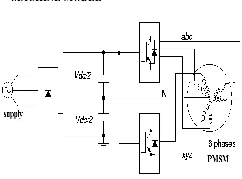
MACHINE MODEL
Fig. 1: Six-Phase machine drive system
Fig. 1 shows a six-phase machine drive system which have a permanent magnet synchronous motor whose stator winding is spatially shifted by 30 electrical degrees with isolated neutral points which is fed by two three phase voltage source inverter, In this study, a six-phase PMSM with two three phase winding is adopted where abc winding is spatially 30 electrical degrees phase led to xyz winding. The phase voltage and flux linkage equations in he stationary reference frames for abc winding and xyz winding of six phase PMSM are shown:
where = is the stator resistance
vector; is the phase voltage
vector of abc winding; = is the current vector of abc winding;
is the phase voltage vector of xyz winding; = is the current vector of xyz
Int. J. of Engg. Sci. & Mgmt. (IJESM), Vol. 3, Issue 4: Oct-Dec.: 2013, 5-13
5-13 inductance vector of xyz winding; and are the
mutual inductance vectors is the permanent magnet flux linkage vector of abc winding ; Ø’mxyz is the permanent magnet flux linkage vector of xyz
winding .
To control the six-phase PMSM, following transformation matrixes have been used to transfer the above equations into synchronous rotating reference frame:
where; Tdq1 is the transformation matrix for abc winding; Tdq2 is the transformation matrix for xyz winding; θe is the rotor flux angle. However, the machine model of a six phase PMSM can be described in synchronous rotating reference frame as follows [14], [15]:
where and are the d-q axis voltages of abc winding ; and are the d-q axis voltages of xyz winding and are the d-q axis currents of abc
windings; and are the d-q axis currents of xyz windings; and are the d-q inductance of abc
winding; and are the d-q inductance of xyz
winding; is the rotor angular velocity; is the electrical angular velocity; is the permanent magnet flux linkage; p is the number of pole pairs of six-phase PMSM. Developed torque can be represented by following equation:
Six-phase PMSM works on the basic principle based on field oriented control in which both and in (12) are set to be zero then d-axis flux linkages [(Ld11id11 + Ø’m ) iq1 + ( Ld11– Lq11) id1 iq1] are fixed due to Ø’m is a constant for a six-phase PMSM. Mechanical dynamic equation of six phase PMSM is:
where J is inertia of six-phase PMSM; B is the damping coefficient ; TL is the load torque.
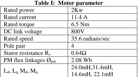
BLOCK DIAGRAM OF SIX-PHASE PMSM DRIVE
Int. J. of Engg. Sci. & Mgmt. (IJESM), Vol. 3, Issue 4: Oct-Dec.: 2013, 5-13
5-13 which is a voltage source inverter, controlled by
PWM.
The reference generator generates a reference signal for each of the phase. To generate the reference signals, it requires the position of the rotor which is supplied by the Theta generation block (Integrator). The feedback current signals and the reference signals are fed in to the current controller. The error between the actual currents and the reference currents are used as modulating signals. The output from the current controller is used for gating the switches of the inverter. The above figure shows the six-phase PMSM drive model consisting the simulink model of six-phase permanent magnet synchronous motor which can be built by using mathematical equations, two three-phase IGBT based voltage source inverter whose gating signals are provided by PWM generators, park’s transformation block to convert abc coordinates of inverter to dq coordinates of motor, PI controller, inverse park’s transformation block.
Control of six-phase PMSM motors is performed using field oriented control for the operation of synchronous motor as a dc motor. An inverter fed the stator windings of motor that generates a variable frequency variable voltage. As an alternative of controlling the inverter frequency independently, the phase and frequency of the output wave are controlled using a position sensor. Field oriented control was invented in the beginning of 1970s and it demonstrates that an induction motor or synchronous motor could be controlled like a separately excited dc motor by the orientation of the stator mmf or current vector in relation to the rotor flux to achieve a desired objective. In order for the motor to behave like DC motor, the control desires knowledge of the instantaneous rotor flux position or rotor position of permanent magnet motor. Knowing the position, the three phase currents can be calculated. The vector control separates the torque component of current and flux channels in the motor through excitation in stator. The vector control of the permanent magnet synchronous motor is derived from its dynamic model.
The vector controller block computes the six reference motor line currents and generates the error signal which is given to corresponding PWM generator and this signals act as gating signals for inverter. Then the signals are sent to Inverse Park’s transformation block (also called as abc-dq transformation block) and then send to six-phase motor.
SIMUALTION RESULTS
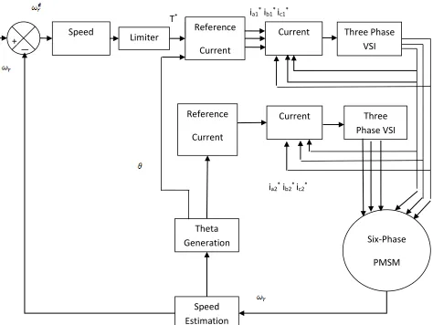
Simulation of Six-phase PMSM is carried out using MATLAB/SIMULINK. The machine parameters are presented in TABLE I.
Table I: Motor parameter
Rated power 2Kw
Rated current 11.4 A
Rated torque 6.5 Nm
DC link voltage 800V
Rated speed 35.6 radians/sec
Pole pair 4
Stator resistance Rs 0.64Ω PM flux linkages Øpm 2.08 Wb
Ld, Lq, Md, Mq 24.0mH,31.4mH, 14.6mH, 22.1mH The system was subjected to different load conditions. The Permanent Magnet Synchronous Motor was operated for a reference speed of 35.6 rad/sec under the following conditions
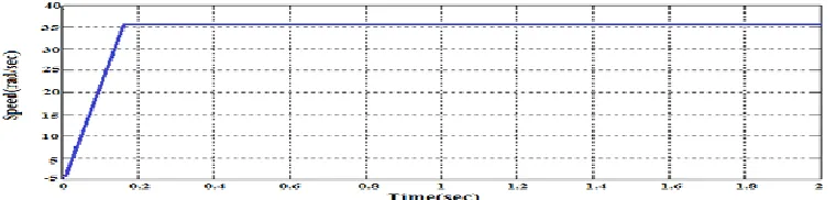
CASE-I: At no-load condition
The simulation result with PI controller with no load torque is applied to the motor and its speed characteristics (fig. 3), torque characteristics (fig. 4) & current characteristics (fig. 5) as shown below. CASEII: With change in load condition
Sudden change in load is applied to the motor from no load to 5 Nm load at 1.2 seconds. At this point waveform is distorted for few second or there is a fluctuation in speed for few seconds and at point 1.25 seconds motor again attained the normal speed and its speed characteristics (fig. 6), torque characteristics (fig. 7) current characteristics (fig. 8) are as shown below:
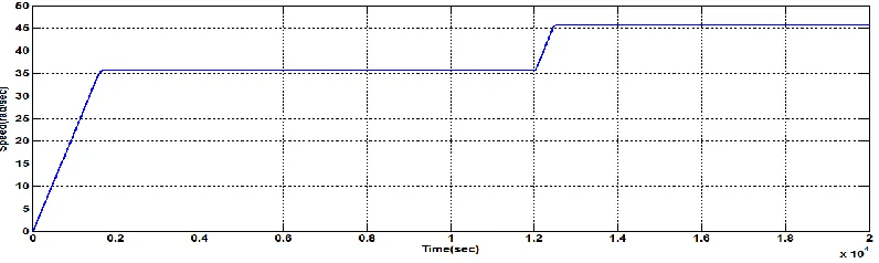
CASEII: With change in reference speed Condition
When initial reference speed is 35.6rad/sec and it changes to 45.6 rad/sec at t = 1.2 sec. initially motor gains its normal speed 35.6rad/sec and at 1.25 sec it is shifted to 45.6 rad/sec. That means PI-controller is sensitive to variation of the reference speed attention and its speed characteristics (fig. 9), torque characteristics (fig. 10) & current characteristics (fig. 11) are as shown below:
CONCLUSION
Int. J. of Engg. Sci. & Mgmt. (IJESM), Vol. 3, Issue 4: Oct-Dec.: 2013, 5-13
5-13 Mathematical and simulated modelling of six phase
PMSM with six phase stator winding in synchronous reference frame is elaborated. Six phase current with 30 degrees phase shift can be easily seen in this paper.
Because the conventional field oriented control does not take into account the magnetic coupling between the winding sets, the dynamic performance will decrease. However, a correct steady- state operating point will be achieved.
REFERENCES
1. E. Levi, “Multiphase electrical machines for variable-speed applications,” IEEE Trans.
Appl.vol 55, pp. 1893-1909 , May-2008.
2. E. Levi, R. Bojoi, F. Profumo, H.A. Toliyat and S.Williamson “Multiphase induction motor drive – a technology status review,”
IET Electr. Power. Appl. vol. 04, pp.
489-516, 2007.
3. J. C. Salmon and B. W. Williams ,”A
split-wound induction motor design to improve reliability of PWM inverterdrives,” IEEE
Trans. Indust. Appl. vol. 26, no. 1 , pp.
143-150, 1990
4. H. Zhang, A. Jouanne, S. Dau, K. Wallace, and F. Wang, “ Multilevel inverter modulation schemes to eliminate common-mode voltages,” IEEE Trans. Appl. vol. 36,no. 6 , pp. 1645-1653, 2000.
5. S. Green, D. J. Atkinson, A. G. Jack, B. C. Mecrow and A. King,” Sensorless operation of a fault tolerant PM drive,” IEE Proc.
Electr. Power. Appl. vol 150,no . 2, pp.
117-125, 2003.
6. R. O. C. Lyra and T. A. Lipo, “Torque density improvement in a six-phase induction motor with third harmonic current injection,”
IEEE Trans, indust. Appl. , Proc. Electr.
Power. Appl. vol 38,no . 5, pp. 1351-1360,
2002.
7. Duran M. J., Salas F., Arahal M. R., “ Bifuration Analysis of Five–Phase Induction Motor Drives With Third Harmonic Injection,” // Industrial Electronics, IEEE
Transactions on,2008. – vol. 55, no. 5. – pp.
2006–2014
8. Singh G. K., Nam K., Lim S. K.,” A Simple Indirect Field-Oriented Control Scheme for Multiphase Induction Machine,” Industrial
Electronics, IEEE Transactions on, 2005. – vol 52. – no. 4. – pp. 1177–1184.
9. Levi E. Editorial – Special Issue on Multi– Phase Motor Drives // EPE Journal, 2004. – vol. 14, No. 3. – pp. 4.
10. H. A. Toliyat, T. A. Lipo, and J. C. White, “ Analysis of a concentrated winding induction machine for adjustable speed drive applications.Motor design and performance,”
IEEE Transactions Energy Conversion, vol.
6, pp. 684- 692, Dec 1991.
11. M. A. Fnaiech, F. Betin,G. Capolino, and F. Fnaiech, “Fuzzy logic and sliding-mode controls applied to six-phase induction machine with open phases,” IEEE Trans. Vehicu. Techn., vol. 56, no. 2, pp. 519-528,2007. G. Eason, B. Noble, and I.N. Sneddon, “On certain integrals of Lipschitz-Hankel type involving products of Bessel functions,” Phil. Trans. Roy. Soc. London, vol. A247, pp. 529-551, April 1955.
12. I. boldea, and S. A. Nasar, Linear electric actuators and generators.London U.K.: Cambridge University Press,1997.
13. R. Kianinezhad, B. Nahid-Mobarakeh, L. Baghli, F. Betin, and G. Capolino,”Modelling and controlof six-phase symmetrical Induction machine under fault condition with open phases,” IEEE Trans.
Indust. Appl, vol. 55, no. 5, pp. 1966-1977,
2008.
14. B. Kundrotas, S. Lisauskas, R. Rinkeviciene,” Model of Multiphase Induction Motor,” ,” IEE Proc. Electr.
Power. Appl. vol. 111,no. 5, pp. 1392-1215,
2011.
Int. J. of Engg. Sci. & Mgmt. (IJESM), Vol. 3, Issue 4: Oct-Dec.: 2013, 5-13
5-13 BLOCK DIAGRAM OF SIX-PHASE PMSM DRIVE
Fig. 2 Block Diagram of Six-Phase PMSM Drive System
Three Phase
VSI
i
a1*i
b1*i
c1*Speed
Controller
Limiter
Reference
Current
Generator
Current
Controller
Speed
Estimation
T
*+
+
+
Three
Phase VSI
Six-Phase
PMSM
Theta
Generation
Reference
Current
Generator
Current
Controller
Int. J. of Engg. Sci. & Mgmt. (IJESM), Vol. 3, Issue 4: Oct-Dec.: 2013, 5-13
5-13 Fig. 3: Speed response at no-load
Fig. 4: Torque response at no-load
Fig. 5: Current response at no-load
Int. J. of Engg. Sci. & Mgmt. (IJESM), Vol. 3, Issue 4: Oct-Dec.: 2013, 5-13
5-13 Fig. 7: Torque response at dynamic load
Fig. 8: Current response at dynamic load
Int. J. of Engg. Sci. & Mgmt. (IJESM), Vol. 3, Issue 4: Oct-Dec.: 2013, 5-13
5-13 Fig. 10: Torque response at change in reference speed