509 | P a g e
MODELING OF DSTATCOM USING NON LINEAR
LOAD
1
Sunil R. Chavan,
2Prof.S.S.Hadpe
1
PG Scholar ELECTRICAL MCOE&RC Nashik (Pune University)
2
Assistant Professor ELECTRICAL Dept. MCOE& RC Nashik,(India)
ABSTRACT
In this paper Distribution Static Compensator (DSTATCOM) which taking into account multi-Level Cascaded H – bridge (CHB) Inverter for minimization of harmonics and compensate reactive power in Power System. This
CHB based inverter supply low harmonics distortion, reduced number of switches, suppression of switching losses and take out the Total Harmonics Distortion (THD). It dispense with the Total Harmonics Distortion (THD) drawn from the nonlinear load for example, switch mode power supply (SMPS), uninterruptable power supply (UPS) To improve the control performance of multi sampled multilevel inverter in contrast to the bipolar switched inverter, the small-signal z-domain model is derived. A level shifted PWM (LSPWM) strategy is utilized to investigate the execution of CHB Inverter. The outcomes are load voltage, current, reactive power,
active power, power factor and harmonics gotten through Matlab.
Keywords: DSTATCOM, LSPWM, SMPS, THD, UPS
I. INTRODUCTION
In power distribution networks, reactive power is required to maintain the voltage to deliver active power
through distribution lines. Conventionally, Static Var Compensators (SVCs) have been used in conjunction with
passive filters at the distribution level for reactive power compensation and mitigation of power quality
problems. Another compensating system has been proposed by, employing a combination of SVC and active
power filter, which can compensate three phase loads in a minimum of two cycles. Thus, a controller which
continuously monitors the load voltages and currents to determine the right amount of compensation required by
the system and the less response time should be a viable alternative. Distribution Static Compensator
(DSTATCOM) has the capacity to overcome the above mentioned drawbacks by providing precise control and
fast response during transient and steady state, with reduced foot print and weight. A DSTATCOM is basically a
converter based distribution flexible AC transmission controller sharing many similar concepts with that of a
Static Compensator (STATCOM) used at the transmission level. At the transmission level, STATCOM handles
only fundamental reactive power and provides voltage support, while a DSTATCOM is employed at the
distribution level or at the load end for dynamic compensation. The latter, DSTATCOM, can be one of the
viable alternatives to SVC in a distribution network. Additionally, a DSTATCOM can
also behave as a shunt active filter, to eliminate unbalance or distortions in the source current or the supply
voltage, as per the IEEE-519 standard limits. Since a DSTATCOM is such a multifunctional device, the main
510 | P a g e
its multi functionality to the maximum. Prior to the type of control algorithm incorporated, the choiceof converter configuration is an important criterion. The two types of converter configurations are voltage
source converter and current source converter, in voltage source converter passive storage elements capacitor
and in current source inverter an inductor use. Normally, voltage source converters are preferred due to their
smaller size, less heat dissipation and less cost of the capacitor, as compared to an inductor for the same rating.
This project focuses on the harmonics produces due to nonlinear load and Level shift pulse width modulation
(LSPWM) controlling technic are use for the cascaded H bridge inverter.. The following indices are considered
for comparison – measurement and signal conditioning requirement, performance with varying nonlinear load,
total harmonic distortion (THD), DC link voltage variation, switching frequency and sampling frequency. The
project briefly describes the level shift pulse width modulation technic. The project also emphasizes the z
domain model is derived to analyse multisampled multilevel inverter of current control technique, as it
significantly affects the performance of a DSTATCOM. A dynamic simulation model of the DSTATCOM
has been developed in Matlab.
II. OPERATING PRINCIPLES OF THE D-STATCOM
Fig.1Single line diagram of the voltage source inverter based DSTSTCOM
Basically, the STATCOM system is comprised of three main parts: a VSI, a set of coupling reactors or a step-up
transformer, and a controller. In a very-high-voltage system, the leakage inductances of the step-up power
transformers can function as coupling reactors. The main purpose of the coupling inductors is to filter out the
current harmonic components that are generated mainly by the pulsating output voltage of the power converters.
The single line diagram of the STATCOM system is illustrated in Figure 1. In principle, the exchange of real
power and reactive power between the STATCOM and the power system can be controlled by adjusting the
amplitude and phase of the converter output voltage. In the case of an ideal lossless power converter, the output
voltage of the converter is controlled to be in phase with that of the power system. In the case of an ideal
lossless power converter, the output voltage of the converter is controlled to be in phase with that of the power
system. In this case, there is no real power circulated in the STATCOM therefore, a real power source is not
needed. To operate the STATCOM in capacitive mode or Var generation the magnitude of the converter output
voltage is controlled to be greater than the voltage at the PCC. In contrast, the magnitude of the output voltage
of the converter is controlled to be less than that of the power system at the PCC on order to absorb reactive
power or to operate the STATCOM in inductive mode However in practice; the converter is associated with
internal losses caused by non-ideal power semiconductor devices and passive components. As a result without
any proper controls the capacitor voltage will be discharged to compensate these losses and will continuously
decrease in magnitude. To regulate the capacitor voltage, a small phase shift is introduced between the converter
511 | P a g e
III. NON LINEAR LOAD
Nonlinear loads used in industries introduce current harmonics at the utility. This causes malfunctioning of the
sensitive loads connected at the PCC. Hence harmonic analysis of the nonlinear loads is essential. Computer
simulation is the most convenient way of harmonic analysis provided that the system components are modelled
accurately and verified either through measurements or mathematically. This can be used for estimating the
harmonic currents injected at PCC by an industry. The current and voltages of the industrial loads are
nonsinusoidal due to their nonlinear characteristics.
Personal Computer (PC)
Personal computers are one of the most widely used electronic loads in modern life. It produces harmonic
current especially when there is a large concentration of them in a distribution system. It utilizes the switch
mode power electronics technology which draws highly non-linear currents that contain large amounts of third
and higher order harmonics. A switch mode power supply (SMPS) has a large capacitor which maintains
approximately constant voltage for the DC bus in the power supply.
IV. CONTROL STRATEGIES
Satisfactory performance, fast response, flexible and easy implementation are the main objectives of any
compensation strategy. The control strategies of a DSTATCOM are mainly implemented in the following steps:
• Measurements of system variables and signal conditioning
• Generation of firing angles for switching devices
I. Pulse Width Modulation (PWM) technic
Two main types of PWM technic are mostly used
a. Level Shift Carrier PWM
b. Phase Shifted Carrier PWM
In this project Level Shift Carrier (PWM) technicare use
.
a. Level Shifted Carrier PWM (LSCPWM)
Fig.2Level shifted carrier PWM
Fig.2 Multilevel carrier-based PWM showing carrier bands, modulation waveform, and inverter output
waveform. Multilevel inverters by making the use of several triangular carrier signals and one reference signal
per phase. For an m-level inverter, m-1 carriers with the same carrier frequency fc and same peak-to-peak
512 | P a g e
The reference, or modulation, waveform has peak-to-peak amplitude Am and modulation frequency fm, and itis centered in the middle of the carrier set. The reference is continuously compared with each of the carrier
signals. If the reference is greater than a carrier signal, then the active device corresponding to that carrier is
switched on and if the reference is less than a carrier signal, then the active device corresponding tothat carrier is
switched off. In multilevel inverters, the amplitude modulation index Ma, and the frequency ratio Mf, are
defined as
M
a =
(1)
M
f =(2)
For carriers signals, the time values of each carrier waves are set to [0 (1/fs)*1/2 1/fs] while the outputs values
are set [0 10] according to the disposition of carrier waves. After comparing, the output signals of comparator
are transmitted to the IGBT.
The carrier waves and the modulating signals are compared and the output of the comparator defines the output
in the positive half cycle the comparator output will have the value high, if the amplitude of the modulating
signal is greater than that of the carrier wave and zero otherwise. Similarly for the negative half cycle, if the
modulating signal is lower than the carrier wave the output of the comparator is high and zero otherwise. In the
five-level cascaded multilevel inverter each carrier waveform and sine waveform are compared individually.
The each comparator output is given to cascaded multilevel inverter switching devices.
V. MATLAB/SIMULINKMODELING AND SIMULATION RESULTS
SIMULINK model of DSTATCOM is shown in Fig. 3 It having the blocks is source block, control block, APF
block, non linear load block and measurements block. The system parameters for simulation study are source
voltage of 415v, 50 Hz AC supply, Source resistance of 0.04 ohm and inductance of 0.5mH, Inverter series
resistance and capacitance 5 ohm and 5 µF respectively. Load resistance and inductance are chosen as 8 ohms
and 100mH respectively.
513 | P a g e
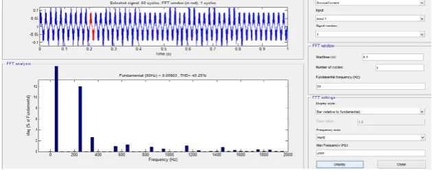
USE SMPS AS NON LINEAR LOAD
FFT ANALYSIS
Figure 4 shows that total harmonics distortion without DSTATCOM is 45%
Fig.4 THD without DSTATCOM
514 | P a g e
Fig.6 THD with DSTATCOM Fig.6 shows THD with DSTATCOM is 13%
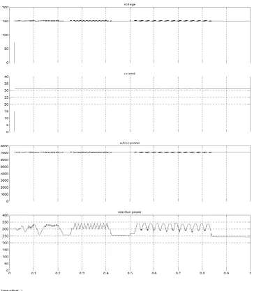
Fig.7 Load Active,Reactive power with DSTATCOM
USING UPS AS NON LINEAR LOAD
515 | P a g e
Fig.8 THD without DSTATCOM
Fig.8 shows total harmonics distortion without DSTATCOM is 870%
Fig.9 Load Active, Reactive power without DSTATCOM
516 | P a g e
Figure 10 shows total harmonics distortion with DSTATCOM is 3.69%Fig.11 Load Active, Reactive power with DSTATCOM
VI. CONCLUSION
Level shift Pulse width modulation (LSPWM) constructed and assesses its execution DSTATCOM with five
level CHB inverter is displayed in this thesis. The source current, source voltage, load current, load voltage,
active power, reactive power, recreation comes about under nonlinear load with STATCOM and without
STATCOM are displayed. Utilizing multilevel converters to minimize the total harmonics distortion. The
517 | P a g e
REFERENCES
[1]. Gishin Jacob George, Rakesh R., Dr. M. Kowsalya ‘Modeling of STATCOM under Different Loading
Conditions’ IEEE Press ,2012
[2]. N.G.Hingorani and L.Gyugyi, ‘Understanding FACTS-Concepts and Technology of Flexible AC
Transmission Systems, IEEE Press, New York, 2000.
[3]. K.R. Padiyar, ‘FACTS Controllers in Power Transmission and Distribution’, New Age Publishers ,India,
2007
[4]. J. Ganesh Prasad Reddy, K. Ramesh ReddyDesign and Simulation of Cascaded H-Bridge Multilevel
Inverter Based DSTATCOM for Compensation of Reactive Power and Harmonics,1 Infl Conf. on Recent
Advances in Information Technology I RAIT-20121
[5]. Prof. B.S.Krishna Varma, G.Vineesha, J.Trupti kumar, K.Sasank, P. Naga Yasasvi Simulated Control
System Design of a Multilevel STATCOM for Reactive Power Compensation IEEE-international
Conference On Advances In Engineering, Science And Management (ICAESM -2012) March 30, 31,
2012
[6]. Leon M. Tolbert, Thomas G. Habetler, Novel Multilevel Inverter Carrier-Based PWM Methods IEEE IAS
1998 Annual Meeting, St. Louis, Missouri, October 10-15, 1998, pp. 1424-1431.
[7]. Ravilla Madhusudan, G. Ramamohan Rao, Modeling and Simulation of a Distribution STATCOM
(D-STATCOM) for Power Quality Problems-Voltage Sag and Swell Based on Sinusoidal Pulse Width
Modulation (SPWM), IEEE- International Conference On Advances In Engineering, Science And