Application and Relational Database Co-Refactoring
Ondrej Macek1and Karel Richta2
1 Dept. of Computer Science and Engineering, Faculty of Electrical Engineering, Czech Technical University in Prague
Karlovo namesti 13 121 35 Praha 2, Czech Republic
Dept. of Software Engineering, Faculty of Mathematics and Physics, Charles University
Malostranske namesti 25 118 00, Praha 1, Czech Republic
Abstract. A refactoring of application persistent objects affects not only the source code but the stored data as well. The change is usually processed in two steps: refactoring and data migration, which is ineffective and error prone. We provide a formal model for solution which is capable to migrate database according to a refactoring in the application code. The feasibility of the change and its data-secure processing is addressed as well.
Keywords:refactoring, relational schema evolution, application and database co-evolution, formal model
1.
Introduction
The Evolution (change) of a software is a common issue during the software development. It occurs for many reasons in all phases of the software lifecycle. The evolution severity usually depends on the number of changes which have to be made and on the number of affected software components. Refactoring [8] is a very popular practice in object-oriented environments for evolving the source code and software architecture. Evolution of database schema and stored data is implemented separately from source code refactor-ing, although the change of application also affects the database. Object-relational map-ping (ORM) frameworks can help with propagation of the evolution from an application to a database. However, these frameworks are usually neither capable of solving complex refactoring cases nor they migrate data properly as it will be shown in Sect. 2.
2.
Refactoring in the Context of ORM
A software implemented by using an object-oriented language, which uses a relational database as a data storage, consists of four main components. There is the application itself, the database schema, stored data and the object-relational mapping. The software can be evolved by adding or removing entities, their properties or associations. These changes affects the database directly. Other kind of evolution is refactoring. Refactoring is a change made to the internal structure of software to make it easier to understand and cheaper to modify without changing its observable behavior [8]. The refactoring may affect not only the application but the database as well. The database has to evolve when the persistence layer of the application changes to fit the object-relational mapping used in the software. The common current solution is based on capabilities of object-relational mapping frameworks which are capable of creating a database schema according to the given source code or model. The process of evolution then proceeds as follows:
1. The code is refactored (usually by using the developer’s IDE). 2. The ORM framework generates a new database schema.
3. The data are migrated manually (if needed) from the old to the new database.
The last step is error-prone as it is processed manually and the error probability increases with the complexity of the refactoring. The evolution process requires cooperation of a developer and a database administrator or it requires the developer to have a knowledge of the database used in the software. The knowledge of the ORM is needed in both cases. Remarkable is the fact that the feasibility of data evolution has to be verified for each deployed software instance, because the data can differ. The data and information preser-vation is a crucial issue of database evolution. The next obserpreser-vation is that the evolution of the software is defined twice for one software - first for the application then for the database.
Example 1 Let us have only two classesAandBin the application which are not con-nected by an association and there are corresponding tablestab aandtab bin the database, which contain some data. We decide to mergeAwithBduring the development. It means (on a structural level) that the result of the merging is a new classA’, which contains all properties of oldA and all properties ofBandBis removed from the application. The database schema is generated by the ORM framework automatically and it contains only the table tab a’’. The data migration has to be created manually. The developer has to define the evolution twice. The mapping between the data in tab aandtab b(a carte-sian product of data in both tables, equality of some columns etc.) has to be provided to merge the stored data correctly. Next the impact of this mapping on the database has to be verified: are there any data which can be lost during inlining and is this loss intentional?
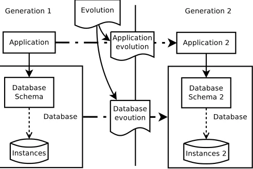
We propose a better solution where the process of database evolution according to the code refactoring is more automatized. The solution is illustrated in Fig. 1. It is based on a change in the evolution process which assumes that the ORM does not change during the evolution:
1. The evolution of the whole software is defined independently of the application or the database.
3. The evolution is executed.
The process can decrease mistakes in the evolution process, because there is only one source for the evolution and the evolution is automatically interpreted for the application (as a refactoring) and database (as schema and data migration). The existence of the set of all possible software evolutionsE is based on a set of evolutionary transformations specific for an application and a database. Each transformation contains conditions of transformation feasibility, thus the feasibility of the evolution can be verified.
Fig. 1.The evolution of data changes the system on all levels. The figure shows all components of the evolution process.
The setEis created with respect to the needs of a developer, therefore the evolution-ary cases are similar to the refactoring cases. Nevertheless the refactoring itself does not provide enough information for the complex migration of database and data, therefore the inputs of some transformation inEare extended beyond normal refactoring inputs. We fo-cus on refactorings (i.e. structural changes) in this paper, therefore some transformations are not mentioned in the paper (e.g. adding data).
3.
Model of Software Evolution
Model-driven development (MDD) is a good approach to data evolution of various soft-ware components [19]. The softsoft-ware is represented by a set of models – concretely, an application model and a database model. The evolution and ORM is represented by a set of model-to-model transformations and the interpretation of transformations fromEis a model-to-model transformation again.
3.1. Software Model
The software consists of three important components (as seen in Fig. 1): an application (its persistence layer concretely), a database (consisting of a database schema and stored data) and an ORM, therefore we define a software as a triple consisting of an application and a database which are connected together by an ORM. The software has to be in a consistent state so its users can benefit from its usage. The software is in a consistent state if the application and the database are consistent and the database structure corresponds to the application structure according to the ORM, therefore the software is defined as:
sof tware(a, d, ρ) =
consistentSof tware(a, d, ρ)ifa̸=⊥ ∧d̸=⊥
∧ρ(a) =d
⊥
(1)
a∈Application, d∈Database, ρ∈ORM
where the⊥symbol denotes an inconsistent state of a software or its components.
Evolution of a software is a transformation from one consistent state to another one. These states are called generations of the software and the functions which change the state of the software are called transformations.
3.2. Application Model
The application is defined as follows:
AppType=AP P ST RIN G|AP P IN T EGER|AP P BOOLEAN (2) InheritanceType=SIN GLET ABLE (3) Inheritance= (Label, InheritanceT ype)∪ {OBJ ECT} (4) Property= (Label, AppT ype, Def aultV alue,
Cardinality, M andatory) (5)
Class= (Label, P roperty∗, Association∗, Inheritance) (6) Association= (Label, Class, StartCardinality, EndCardinality) (7)
StartCardinality, EndCardinality∈N0∪ {∗}
Application=Class∗ (8)
Application type Application type (AppT ype) represents primitive types in the applica-tion. Programming languages usually provide types such as String, Integer, Boolean etc. The denotation of types begins with ”APP-” prefix to distinguish them from database types. The type casting (i.e. changing type of a property from String to Integer) is not part of transformations defined in this paper, because we focus on structural changes and their impact on data in the first place. However, type casting can be easily integrated into described transformations.
Inheritance The inheritance defines a parent-child relationship between classes. Multiple ancestors are not allowed and of course a class cannot be its own ancestor directly or indi-rectly. These restrictions are inspired by common programming languages as Java or C#. TheInheritanceTypedetermines how a inheritance hierarchy is mapped into a database. We consider only one common mappings of inheritance into a relational database for the sake of model abbreviation. We decide to represent an inheritance hierarchy of classes as a single table that has columns for all the fields of the various classes [9]. We assume there is only one type of inheritance type per class hierarchy. There can be several independent inheritance hierarchies in the model. The symbolOBJECTrepresents an universal parent for all classes.
Property Property represents a feature of a class which is represented as a primitive type. A property can be mandatory, can have a default value and according to its cardinality it can represent a single value or a collection of values. The properties of non-primitive types are represented as associations.
Class Class represents a basic structural unit in the application model. It has a unique name, one or more properties and it can be associated to other classes in the application.
3.3. Application Manipulation
The application model defines only the structure of an application’s data thus there are defined transformations for adding, altering and removing parts of the model (the setA). Each transformation has a set of preconditions, which are in case of adding or altering very simple:
1. Name collisions have to be prevented when creating a class in the model or altering its name.
2. All references have to be updated when renaming a class.
3. The existence of the class being referenced has to be verified when creating or altering an association.
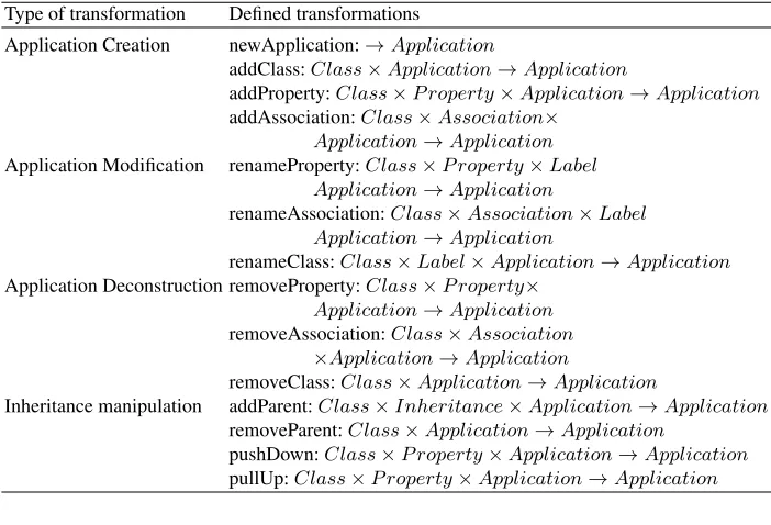
The only problem that can occur while deleting classes etc. from an application is that the class can be removed only when it is not associated with other classes. The list of possible transformations fromAare in Table 1. The list of altering operations is not complete as transformation for changing the obligation or cardinality of properties and associations are missing. It is because these transformations are not so important for complex refactorings.
Table 1.The content of the setA- transformations for application change and refactoring. The detailed specification can be found in [16].
Type of transformation Defined transformations
Application Creation newApplication:→Application
addClass:Class×Application→Application
addProperty:Class×P roperty×Application→Application
addAssociation:Class×Association× Application→Application
Application Modification renameProperty:Class×P roperty×Label Application→Application
renameAssociation:Class×Association×Label Application→Application
renameClass:Class×Label×Application→Application
Application Deconstruction removeProperty:Class×P roperty× Application→Application
removeAssociation:Class×Association ×Application→Application
removeClass:Class×Application→Application
Inheritance manipulation addParent:Class×Inheritance×Application→Application
removeParent:Class×Application→Application
pushDown:Class×P roperty×Application→Application
pullUp:Class×P roperty×Application→Application
3.4. Database Model
is defined as:
DbType=DBST RIN G|DBIN T |DBBOOLEAN (9) Constraint=N OT N U LL|U N IQU E (10) PrimaryKey= (Label) (11) Column= (Label, DbT ype, Def aultV alue, Constraint∗) (12) ForeignKey= (Label, T ableSchema, Constraint∗) (13) TableSchema= (Label, P rimaryKey, Column∗, F oreignKey∗) (14)
Data Types Database data typesDbT yperepresent primitive types in the database. Da-tabases usually provide types such as Varchar, Integer, Boolean etc. We define types for strings, numbers and boolean values which can be further extended according to a speci-fication of a concrete database.
Constraints There are two types of constraints defined in the model. Both constraints are column constraints - the first constraint forces columns to have no non-empty elements, the second constraint requires there have to be unique records in a column or foreign key.
Primary key A primary key is an unambiguous identifier of a record in a table. The primary key is always provided (automatically generated) by the associated sequences as a non-zero natural number. A new value of a key is obtained by calling the function next(s). The generator of primary keys values is calledSequence and there is one se-quence per database in the model (see (18)).
A primary key is always defined with constraintsN OT N U LLandU N IQU E.
Column A column defines data values and types which can be part of a table record.
Foreign key A foreign key is a reference to another table’s primary key, it has a unique name and it can be constrained. The value of a foreign key is a non-zero natural number or∅if not constrained byN OT N U LL.
TableSchema A table represents a basic concept of a database schema. It has a unique name, one or more columns and it can be related to other tables in the schema by foreign keys. Rows in the table represent stored data.
Data A database consists not only of a schema but also of data which are represented as rows in a table. A table row in our model consists of value pairs, which represent concrete values of a concrete column or key. Each row contains a reference to a table it belongs to and a primary key’s value, which uniquely identifies the row.
Database The database is defined by its schema and data it contains. Last important item of a database is a generator of primary key values calledSequence.
Database= (T ableSchema∗, T ableData∗, Sequence) (18)
3.5. Database Manipulation
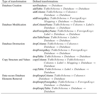
A database consists of two parts - of a database schema, which defines the structure, and of stored data - hence the transformations from setD have to consider both parts. The transformation for manipulation of structure has similar conditions to the evolution of applications. The transformations for data manipulation are inspired by the SQL language. The basic transformations are in Table 2 and the operations for data manipulation are in Table 3. The set of transformations for database manipulation is limited in contrast to the SQL language. Only transformations necessary for data evolution on database level are introduced.
Table 2.The transformations for database evolution. Transformations can be mapped to SQL intu-itively. The detailed specification can be found in [16].
Type of transformation Defined transformations Database Creation newDatabase:→Database
addTable:T ableSchema×Database→Database
addColumn:T ableSchema×Column× Database→Database
addForeignKey:T ableSchema×F oreignKey× M apping×Database→Database
Database Modification alterColumnName:T ableSchema×Column×Label× Database→Database
alterForeignKeyName:T ableSchema×F oreignKey× Label×Database→Database
alterTableName:T ableSchema×Label× Database→Database
Database Destruction dropColumn:T ableSchema×Column× Database→Database
dropForeignKey:T ableSchema×F oreignKey× Database→Database
dropTable:T ableSchema×Database→Database
Copy Structure and Values copyColumn:T ableSchema×T ableSchema×
Column×Label×M apping×Database→ Database
copyTable:T ableSchema×Label×Database→ Database
Data-secure Database dropEmptyColumn:T ableSchema×Column×
Elements Removal Database→Database
dropEmptyForeignKey:T ableSchema×F oreignKey× Database→Database
Table 3.The table contains a set of transformations which serve for data manipulation. The detailed specification can be found in [16].
Data Manipulation selectOne:T ableSchema×ID×Database→T ableData
selectAll:T ableSchema×Database→T ableData∗
insertData:T ableData×Database→Database
insertValue:T ableData×P air×Database→Database
Copying Database Elements The transformations for copying the structure and values of a column or table serve more as helpers for advanced evolution cases, where they are discussed in detail.
Data-Safe Database Element Removal The transformation that remove elements from the database can have fatal impact on the data preservation, therefore the set of transfor-mations is extended by data safe transfortransfor-mations for removing database elements. These transformations are not part of the SQL standard, although they can be implemented as database functions. These transformations create a safe way to remove elements from the database as they drop empty structural elements only.
3.6. Mapping Between Stored Data
A relation between data from differentT ableDatas has to be known during execution of some transformations (e.g.moveP roperty). The relation is defined as a mapping be-tweenT ableDatas. The mapping is defined as follows:
mapping:T ableData→T ableData∗ ∪ {∅} (19)
The mapping has a sequences ofT ableDatain its range set, this allows to define one-to-many and one-to-many-to-one-to-many relations between data. The∅represents a situation where there is no relation for a given element of the mapping’s range. A special case of mapping is an empty mapping denoted as me, which is used when there are noT ableDatain the domain or the range is equal to∅i.e. the transformation takes part on the structural level only. The set of all possible mappings is calledM apping.
Each mapping has to fulfill constraints given by the structural definition of its range T ableData. Concretely: uniqueness of column values:
∀m∈M apping;x1, x2∈domain(m);p1∈pairs(m(x1)), p2∈pairs(m(x2)) : x1̸=x2∧ ∃c∈Column, U N IQU E∈constraints(c)∧
c∈pairs(columns(range(m))) =⇒ p1̸=p2 (20)
if the principle of uniqueness is violated then usage of such a mapping leads to an incon-sistent database. Next constraint of mappings is the non-emptiness of columns constrained withN OT N U LLconstraint:
∀m∈M apping;x∈domain(m) :
if this principle is violated then usage of such a mapping leads to an inconsistent database. There can occur data loss, when the mapping is a partial function. Usage of such mapping has to be reconsidered before its usage, because it can result in a semantically inconsistent state of the database.
A mapping can be implemented as a nested query in the SQL command representing the transformation. Alternatively, a database view can be implemented to represent such a mapping.
3.7. Object Relational Mapping
ORM is the only fixed point in the software model we use. The mapping is similar to the Hibernate mapping [13], thus a lot of developers should be familiar with it. The main ideas are:
– classes are mapped to tables,
– single properties are mapped to a column or if the property is a collection then the property is mapped as a table,
– associations are mapped to foreign keys or to tables if the association represents a many-to-many relationship,
– primary keys are created automatically for each table,
– names used in application are mapped into the database schema (e.g. because of pos-sible name collision of application classes and names of database schema elements).
3.8. Software Evolution
The evolution of the whole software is described from the developer’s point of view, there-fore the transformations use the names and elements from application context. Elements have to be transformed into a database context - this is assured by the ORM. In the model we ignore the fact an element’s label has to be often transformed as well (e.g. because of collision between the label and label of a database internal table).
Three sets of transformations have to be defined to provide the capabilities described in Example 2: the setEof all possible software transformations:
E={e|e:ConsistentSof tware→Sof tware}, (22)
which is limited in this paper to a set of transformations for refactoring, creating and deleting model elements. The list of transformations and their definition is available online [16]. The fact that a transformation producesSof twareand notConsistentSof tware supports composition of transformations. If a transformation (refactoring) is applicable on a software it produces consistent software. In contrast if the transformation is not applicable than the software is in the state⊥and no transformation can change it.
Next we define the set of application refactorings:
A={a|a:Application→Application} (23)
and the set of database evolutionary transformations
Evolution of the software is defined as an interpretation of the transformation for each component of the software:
t(s) =sof tware(Ψ(t, application(s)), Φ(t, database(s)), ρ(s)) (25) s∈ConsistentSof tware, t∈E
whereΨ : E×Application → Ainterprets the software evolution cases to the code refactoring andΦ:E×Database→Dinterprets to the evolutionary transformation of database. The ORM does not change during the evolution.
The advantage of interpretation is that the semantics of the evolution is defined only once by theE-transformation. This definition contains all necessary information for par-tial evolutions of all software components. This approach speeds up the work of software developers, because it automatize the process of database evolution.
3.9. Basic Evolutionary Transformations
The evolution of the whole software is based on the atomic transformations specific for each software part, which are defined in Sec. 3.3 and 3.5. This section introduces how those primitives can be used to manipulate the software elements.
The basic evolutionary transformations of the software are based on basic evolution of an application. These transformations have to respect the ORM, because properties and associations can be mapped as a column (foreign key respectively) as shown in the example of creating a new property:
Φ(newP roperty(c, p), d) =
addColumn(ORM(c), ORM(p), d)
if cardinality(p) = 1
addF oreignKey(ORM(p), f k, me, addT able(ORM(p), d))
if cardinality(p)>1
wheref k= (ORM(c), ORM(C),⟨⟩)
(26)
c∈Class, p∈P roperty, d∈Database
An example of both mappings is in Fig. 2.
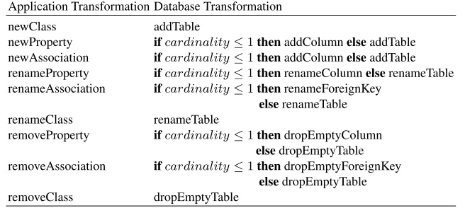
A mapping between basic evolutionary transformations is provided in the short in Ta-ble 4. The detailed definitions are provided in [16]. The mapping can be implemented as a direct generation of SQL commands from the application transformations or an inter-mediate database model can be used. The second approach is suitable if there are multiple models affecting database i.e. a model of entities, which is interpreted as database schema and a model of business constraints, which is interpreted as a set of database triggers.
(a) (b) (c)
Fig. 2. Two possible variants how thenewP roperty transformation can be interpreted on the database level. The initial state is in Fig. 2a, then a new property called Address is added. In case the Address property has cardinality equal to 1 then the result is in Fig. 2b otherwise the result is in Fig. 2c.
Table 4.The mapping between evolution of the application and database transformations. The ad-vanced transformations are explained in detail in Sect.3.10.
Application Transformation Database Transformation
newClass addTable
newProperty ifcardinality≤1thenaddColumnelseaddTable newAssociation ifcardinality≤1thenaddColumnelseaddTable renameProperty ifcardinality≤1thenrenameColumnelserenameTable renameAssociation ifcardinality≤1thenrenameForeignKey
elserenameTable
renameClass renameTable
removeProperty ifcardinality≤1thendropEmptyColumn elsedropEmptyTable removeAssociation ifcardinality≤1thendropEmptyForeignKey
transformations for data-safe removal are used as default removing transformations, al-though the classic drop- transformations can be used. This should lead to the more careful usage of removing transformations.
3.10. Advanced Evolutionary Transformations
Advanced evolutionary transformations are based on the basic ones, they can be obtained as a concatenation of transformations. This means the complex transformations are lim-ited in the same way as their basic components. All transformations from the setE pre-sented so far have the same input information for both an application and a database, whereas the advanced transformations usually need a mapping between stored data (in-stances) as their input.
Copy Property ThecopyP ropertycreates a duplicate of a property in a given class. If the mapping is not provided the transformation creates only a structural copy of the property, otherwise it copies the values too. Therefore thecopyP ropertytransformation is the simplest way to manipulate the stored data.
copyP roperty:Class×Class×P roperty×M apping×
ConsistentSof tware→Sof tware (27)
ThecopyP ropertyis the first transformation when an additional information has to be added to the usual code refactoring. It is because thecopyColumntransformation needs one more information to succeed - a mapping has to be provided between the source and the target table to assure data information consistency. The transformation is interpreted for both software components - in the application case a new property is added:
Ψ(copyP roperty(cs, ct, p, m, s)) =newP roperty(ct, p, application(s)))
ifcs̸=ct (28)
In the database case the copy of a column or table is created according the cardinality of the property and then the values are copied:
Φ(copyP roperty(cs, ct, p, m, d) =
copyColumn(ORM(cs), ORM(ct), ORM(p), m, database(s))
if cardinality(p) = 1
copyP ropertyAsT able(ORM(cs), ORM(ct), ORM(p), m, database(s)) if cardinality(p)>1
(29)
cause loss of data. The ideal case is when the mapping is injective, then the transformation cannot cause loss of data.
moveP roperty:Class×Class×P roperty×M apping×
ConsistentSof tware→Sof tware (30)
moveP roperty(cs, ct, p, m, s) =
removeP roperty(cs, p, copyP roperty(cs, ct, p, m, s)) (31)
Inline and Split Class Inline and split are two opposite transformations. First of them moves data from the source class into the target one and then deletes the source class. Second of them extracts a new class from an existing class. The inline transformations can be composed from already mentioned basic transformations:
inlineClass:Class×Class×M apping×
ConsistentSof tware→Sof tware (32)
inlineClass(c1, c2, m, s) =removeClass(c2, moveP roperties(c1, c2, m, s))
if !isRef erenced(c2, application(s)) wherep∈properties(c2),
moveP roperties(c1, c2, m, s) =
∀p∈properties(c2) :moveP roperty(c1, c2, p, m, s) (33)
A special case of inlining is merge. ThemergeClasstransformation is used when two classes have the same structure and they should be merged into one.
mergeClasses:Class×Class×Sof tware→Sof tware (34)
The classes are represented as two tables containing different data - these data have to be merged into one table.
The split transformation has to be interpreted:
splitClass:Class×Label×P roperty×
ConsistentSof tware→Sof tware (35)
Ψ(splitClass(c, l, p), a) =removeP roperty(c, p, newP roperty(cn, p,
addClass(cn, a)))
Φ(splitClass(c, l, p), d) =
dropColumn(ORM(c), ORM(p), copyColumn(ORM(c),
ORM(propT oClass(p)), m, addT able(ORM(propT oClass(p, l)), d)))
wherem=∀r∈selectAll(ORM(c), d) :
m(r) =tableData((ORM(propT oClass(p, l)), keyP air(r), pairOf Column(ORM(p), pairs(r))))
if cardinality(p) = 1
alterT ableN ame(ORM(p), l, dropF oreignKey(ORM(p),
f oreignKeys(ORM(p), d))
if cardinality(p)>1
(37)
Themapping is defined as identity in case ofsplitClass, therefore the rows in the new table have the same primary keys’ values as in their source class.
3.11. Inheritance Manipulation
Inheritance is an important part of object-oriented world. The impact of change of this relationship to the database depends on the type of inheritance mapping similarly as in the case ofmoveProperty. TheaddParenttransformation is described as example:
addP arent:Class×Inheritance×M apping×
ConsistentSof tware→Sof tware (38)
The interpretation of theaddP arenttransformation for the whole software on the appli-cation level uses the transformationaddP arentdefined for the application level (see Tab. 1):
Ψ(addP arent(c, ih, m), a) =addP arent(c, ih, a)
if !isRef erenced(c) (39)
The interpretation of theaddP arenttransforation on the database level depends on the ORM. We use the single-table mapping in our model, therefore the result is a merge of tables:
Φ(addP arent(c, ih, m, s) =dropT able(ORM(c), h(c, ih, p, m, s))
whereh:T ableSchema×Inheritance×M apping× Sof tware→Database
h(c, ih, p, m, s) =∀ p∈properties(c) :
Φ(moveP roperty(c, class(ih), p, m, s)) (40)
does not cover the case when the information from parent are not needed in its child, such a transformation has to be defined by a sequence of steps.
Next transformations connected with inheritance arepushDownandpullUp. Pull up moves a property from child to parent so themovePropertycan be used, the mapping of instances is based on the parent-child relationship. It means the column cannot be constrained withN OT N U LLconstraint if there are more siblings in the hierarchy. The pushDowntransformation works in opposite direction, however it moves the property into all children of the parent class. The easiest situation is where there is no sibling in the hi-erarchy, otherwise we assume there are no stored data in the siblings. It is because the change of parent affects the instances of its children: When a property is moved only into one child, the information consistency is violated, therefore we forbid such transforma-tion, because we cannot anticipate developer’s intents.
The next two inheritance-related transformations areextractParentand extractCom-monParentwhich serve for extracting a parent class based on a given set of property from a class or from a couple of classes.
4.
Example of Usage
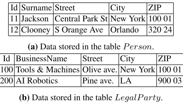
The examples demonstrate how the transformations help with data evolution in real life example of software evolution. There are two classes in our softwarePersonand Legal-Party, both of them contain information about address (street, city and zip code) as shown in the Fig. 3 where the database tables are shown.
To improve the design of code a class representing Address has to be created. The Addressclass shall be associated with both original classes and shall receive the data already stored in the database.
Id Surname Street City ZIP 11 Jackson Central Park St New York 100 01 12 Clooney S Orange Ave Orlando 320 24
(a)Data stored in the tableP erson. Id BusinessName Street City ZIP 100 Tools & Machines Olive ave. New York 100 01 200 AI Robotics Pine ave. LA 900 03
(b)Data stored in the tableLegalP arty.
Fig. 3.The initial state of the example used in the case study. There is a repetition of information structure in theP ersonandLegalP artyclass.
The first step is to extract two temporary classes representing addresses of aPersonor of aLegalParty:
s1=splitClass(P erson,”Address tmp1”,⟨street, city, zip⟩,
sof tware) (41)
ThesplitClasstransformation moves given properties into the new class, therefore there is no address information inPersonorLegalPersonafter these transformations. The tem-porary classes have to be connected with the origin classes by an association.
s3=newAssociation(P erson, association(”address”,
”Address tmp1”,1,1), mapping1, s2) (43) s4=newAssociation(LegalP arty, association(”address”,
”Address tmp2”,∗,1), mapping2, s3) (44)
Themapping1andmapping2can be defined using the equality of primary keys values, because the temporary classes were extracted from thePersonandLegalParty. Finally the temporary class are merged into one:
s5=mergeClasses(Address tmp1, Address tmp2,”Address”, s4) (45)
The merge of classes is possible because the associations (and corresponding foreign keys) created in the previous step are not constrained. The change of the code continue by
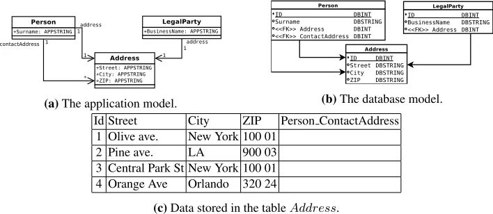
(a)The application model. (b)The database model. Id Street City ZIP Person ContactAddress
1 Olive ave. New York 100 01 2 Pine ave. LA 900 03 3 Central Park St New York 100 01 4 Orange Ave Orlando 320 24
(c)Data stored in the tableAddress.
Fig. 4.The final state of the example used in the case study. There is only one table containing all addresses in the system (see 4b), which is referenced byLegalP artyclass and by the theP erson
and class twice, which represents regular and contact address.
adding more addresses to thePersonclass:
s6=newAssociation(P erson, association(”contactAddress”,
Address,1,1), me, s5) (46)
The final result of the transformations is in the Fig. 4.
5.
Capabilities of Defined Transformations
It is obvious that the set of defined transformation is limited because of focus on data preservation or transformation concatenation. Nevertheless, defined transformations are strong enough to handle a lot of refactoring cases. To verify this we use refactoring cases based on the Eclipse foundation refactoring statistics [7] (choosing only the transforma-tion influencing data) and on Fowler’s book [8]. Selected refactorings are:
1. Renameis the most used refactoring according to the Eclipse statistic and it is one of the basic refactoring cases introduced in Sec. 3.9.
2. Moverefactoring is used in Eclipse to move properties from a class to another class within an inheritance hierarchy or to move classes between packages. In contrast, our model does not consider packages, However it is able to move property from one class to another according to the given mapping, which contains not only moves in hierarchy but a lot of other cases too.
3. Extract Classis an often used refactoring in Eclipse and it is mentioned in Fowler’s book as well. It is introduced as an example of advanced refactorings in Sec. 3.10 as thesplitClasstransformation together with its opposite transformationmergeClasses. 4. Move fieldfrom Fowler’s book is introduced asmovePropertyin Sec. 3.9.
5. Replace Data Value with Objectis a refactoring case which is not mentioned among the evolutionary transformations. However it can be composed from already defined transformations:
replaceDataW ithObject(sourceClass, property, newObject,
sof tware) =removeP roperty(sourceClass, property,
newAssociation(sourceClass, association(label(sourceClass),
newObject,1,1), mapping, copyP roperty(sourceClass, newObject,
property, mapping, sof tware) (47)
where the mapping represents the relation between the new object and the original one - for each instance of the new object there is one instance of the original one.
The transformations proposed in this paper are able to implement all data refactorings supported by the Eclipse IDE. There are some refactorings from Fowler which are not considered in the proposal: replacing array with object, changing unidirectional associa-tion to bidirecassocia-tional (and reverse) and operaassocia-tions which replace types with polymorphism. However, the proposal solves the most used refactorings.
6.
Related Work
Informal definitions The taxonomy of relational database evolution based on the entity-relationship model is proposed in [20]. The evolution is described as a change in the entity-relationship model and a change in a relational database. The semantics change patterns in context of a conceptual schema are described in [25], although its impact on a database schema or data is not described. The main cases of data evolution are defined in both publications. The description is informal. An extensive set of possible database refactorings is provided in [3], where both schema and data evolution is discussed. The refactorings are intended to be used by database administrators, thus it assumes database-first approach to evolution, whereas this proposal is application-database-first.
Formal frameworks A general formal framework for database evolution is defined in [17]. The framework is based on a set of basic graph transformations which are then ex-tended to transformations of the entity-relationship model. The framework and the defined transformations can be implemented in our proposal too. The contribution of the formal framework is a definition of equivalent structures in relational database schemas. Our pro-posal is aimed to be used in the domain of object-oriented languages, where a class model is more common than entity-relationship model.
The formal definition of MDD approach to database schema evolution is proposed in [2], where changes of a database conceptual schema are interpreted on both a physical schema and data. In contrast our proposal is aimed to solve the problem of code refactor-ing and its impact on relational database, next we propose more complex transformations (such ascopyPropertyor inheritance-related transformations) and examine the impact of platform specific constructs (such as foreign keys or constraints) on the evolution.
A categorical framework for the migration of object-oriented systems is proposed in [21]. This framework defines the refactoring of objects, data and methods, which are the main objectives of the framework. The impact of the object change on a relational database is not considered in the paper as it is aimed at object-oriented systems only.
Forward Round-Trip Engineering in Data Evolution A round-trip approach for data evo-lution was described in [23], which was implemented in the SELF language. This ap-proach proposed a forward-oriented evolution on all application levels in the software application. In contrast with our framework, the round-trip approach does not care about stored data, because it is focused only on transformations for creating, updating and delet-ing elements of a model.
A meta-model based approach to data evolution is proposed in [1] where a very similar solution for data evolution is proposed, which is based on an extended UML meta-model. The solution provides similar capabilities of change of application and database as does our proposal. In contrast our work is created with the ORM domain in mind and therefore we extended the application meta-model with constructs typical of this domain.
user SQL commands. Entity Framework [18] is Microsoft’s ORM solution for the .NET platform. Its capabilities of data evolution support are similar to those of Active Record. Neither of the frameworks is capable of automatization of complex refactoring cases.
Tools for Database Evolution The MeDEA project [6] offers a tool for evolution of both database schema and stored data based on model-driven approach. The project DB-MAIN [12] provides a MDD approach to data evolution on all the levels of software we do. The project DB-MAIN is well documented formally. The PRISM is a research project for data management under schema evolution [5]. In contrast with our proposal, and with MeDEA, it extends the SQL command set by so-called schema modification operators which implements the schema evolution. A very promising solution is Liquibase [24], a tool for database refactoring and evolution. It is capable of migrating both database schema and stored data. The evolution is described by an XML document which can be interpreted on various databases.
The difference between these frameworks and our proposal is that each has a different focus. All mentioned projects are aimed to be used by database administrators; whereas our focus is on entities evolution, which is then propagated to a database with an emphasis on automatization. Our goal is to hide the entire database level from our users.
The project IMIS [4] follows the same idea of applying MDD into evolution of a whole software, but does not provide a formal model or an overview of capabilities (defined transformations).
7.
Conclusion
We discuss the impact of application refactoring on relational database schema and stored data. We introduce basic transformations of application and database, next show how the complex refactorings can be constructed based on basic refactorings. The transformations presented are capable of solving the main refactoring cases. Theirs construction assures structural-safe change of application and data-safe migration of database schema and data. The proposal is based on the idea of MDD which is implemented by a set of mod-els and transformation rules. This allows to simulate the behavior of an evolution in the platform independent environment.
The main contribution is the new point of view on the application refactoring. The ap-plication code and relational database co-evolution can improve the capabilities of IDEs and speed up the work of developers. Next contributions are definitions of impact of advanced refactoring cases on relational database and stored data. We show that the au-tomatic co-refactoring is possible not only in case of basic changes of an application, but even complex refactorings can be processed automatically for the applications’ code and database.
Someone can be afraid about applicability in complex scenarios, whether the proposal can really save time in real world scenarios. But due to the fact that hand-crafting of mappings is not necessary in most of the interesting cases (usually an existing association is used as the mapping function), the model proposed has advantages over hand-made migration scripts.
References
1. Aboulsamh, M., Davies, J.: A metamodel-based approach to information systems evolution and data migration. In: Software Engineering Advances (ICSEA), 2010 Fifth International Confer-ence on. pp. 155 –161 (aug 2010)
2. Aboulsamh, M., Davies, J.: A formal modeling approach to information systems evolution and data migration. In: Halpin, T., Nurcan, S., Krogstie, J., Soffer, P., Proper, E., Schmidt, R., Bider, I. (eds.) Enterprise, Business-Process and Information Systems Modeling, Lecture Notes in Business Information Processing, vol. 81, pp. 383–397. Springer Berlin Heidelberg (2011), http://dx.doi.org/10.1007/978-3-642-21759-3_28
3. Ambler, S.W., Sadalage, P.J.: Refactoring Databases: Evolutionary Database Design. Addison-Wesley Professional (2006)
4. Bordbar, B., Draheim, D., Horn, M., Schulz, I., Weber, G.: Integrated model-based software de-velopment, data access, and data migration. In: Proceedings of the 8th international conference on Model Driven Engineering Languages and Systems. pp. 382–396. MoDELS’05, Springer-Verlag, Berlin, Heidelberg (2005),http://dx.doi.org/10.1007/11557432_28 5. Curino, C.A., Moon, H.J., Zaniolo, C.: Graceful database schema evolution: the prism
workbench. Proc. VLDB Endow. 1(1), 761–772 (Aug 2008), http://dl.acm.org/ citation.cfm?id=1453856.1453939
6. Domnguez, E., Lloret, J., ngel L. Rubio, Zapata, M.A.: Medea: A database evolution archi-tecture with traceability. Data & Knowledge Engineering 65(3), 419 – 441 (2008),http: //www.sciencedirect.com/science/article/pii/S0169023X07002224 7. Eclipse Foundation: Usage Data Collector Results (2013),http://www.eclipse.org/
org/usagedata/results.php?kind=command&sort=element[Accesed 19. November 2013]
8. Fowler, M.: Refactoring: Improving the Design of Existing Code. Addison-Wesley, Boston, MA, USA (1999)
9. Fowler, M.: Patterns of Enterprise Application Architecture. Addison-Wesley Longman Pub-lishing Co., Inc., Boston, MA, USA (2002)
10. Hansson, D.H., Kemper, J.: ActiveRecord::Migration (2009), http://api. rubyonrails.org/classes/ActiveRecord/Migration.html, Accessed 6. September 2012
11. Hansson, D.H., Kemper, J.: RubyForge:ActiveRecord: Project Info (2009), http:// rubyforge.org/projects/activerecord, Accessed 6. September 2012
12. Hick, J.M., Hainaut, J.L.: Database application evolution: A transformational approach. Data & Knowl. Eng. 59(3), 534–558 (2006)
13. JBoss Community: Hibernate (2011), http://www.hibernate.org/, Accessed 6. September 2012
14. Jing, J., Claypool, K., Jin, J., Rundensteiner, E.: SERF: Schema Evolution through an Extensi-ble, Re-usable and Flexible Framework. In: Int. Conf. on Information and Knowl. Management (1998)
15. Lerner, B.S., Habermann, A.N.: Beyond schema evolution to database reorganization. ACM, New York, NY, USA (1990)
16. Macek, O., Richta, K.: Transformations for Application and Database Co-Refactoring (2013), https://github.com/macekond/comsis_transformations_appendix [Ac-cesed 19. November 2013]
17. McBrien, P., Poulovassilis, A.: A General Formal Framework for Schema Transformation. Data and knowledge engineering 28(1), 47–71 (September 1998),http://pubs.doc.ic.ac. uk/formal-framework-transformation/
19. Moravec P., Harmanec D, Tarant P., Jezek J.: An practical approach to dealing with evolving models and persisted data. In: Code Generation (2012)
20. Roddick, J.F., Craske, N.G., Richards, T.J.: A taxonomy for schema versioning based on the relational and entity relationship models. In: Proceedings of the 12th International Conference on the Entity-Relationship Approach: Entity-Relationship Approach. pp. 137–148. ER ’93, Springer-Verlag, London, UK, UK (1994),http://dl.acm.org/citation.cfm?id= 647515.727030
21. Schulz, C., L¨owe, M., K¨onig, H.: A categorical framework for the transformation of object-oriented systems: Models and data. J. Symb. Comput. 46(3), 316–337 (Mar 2011),http: //dx.doi.org/10.1016/j.jsc.2010.09.010
22. Tresch, M.: A framework for schema evolution by meta object manipulation. In: Proc. of the 3d Int. Workshop on Found. of Model. and Lang. for Data and Objects (1991)
23. Van Paesschen, E., De Meuter, W., D’Hondt, M.: Selfsync: a dynamic round-trip engineering environment. Model Driven Eng. Lang. and Syst. pp. 633–647 (2005)
24. Voxland N.: Liquibase (2013),http://www.liquibase.org[Accesed 19. November 2013]
25. Wedemeijer, L.: Semantical change patterns in the conceptual schema. In: Proceedings of the Workshops on Evolution and Change in Data Management, Reverse Engineering in Infor-mation Systems, and the World Wide Web and Conceptual Modeling. pp. 122–133. ER ’99, Springer-Verlag, London, UK, UK (1999),http://dl.acm.org/citation.cfm?id= 647523.728210
Ing. Ondrej Macek.He received his MS in 2008 in study programme Electrical Engi-neering and Informatics from the Czech Technical University in Prague. He has been an assistant professor at the Czech Technical University since 2010 where he teaches under-graduate courses software analysis, object oriented design and project management. His research interests are model driven development, databases, software engineering and for-mal specification. He is a member of the Upsilon Pi Epsilon - International Honor Society for the Computing and Information Disciplines and a member of a conference committee of DATESO.
Doc. Ing. Karel Richta, PhD. He graduated from the Czech Technical University in Prague in 1974. Specializes in the area of formal specification and semantics, engaged in programming languages and operating systems, currently focuses mainly on software engineering and database management systems. This topic teaches in the Department of Computer Science & Engineering at Czech Technical University in Prague, and also in the Department of Software Engineering of Charles University in Prague. He has published more than 110 contributions to scientific conferences and in journals. He is a member of numerous program committees, the member of a steering committee of DATAKON conference, and the seminar DATESO. He is the president of the Czech ACM Chapter, the member of TC2 committee of IFIP, the member of Czech Society of Information Systems, the member of Czech Society of Systems Integration, also acts as a permanent reviewer on IEEE Software.