RESEARCH ARTICLE
HIGH EFFICIENCY H6 TRANSFORMERLESS TOPOLOGY BASED SINGLE PHASE
FULL BRIDGE PV GRID TIED INVERTERS
*Madhuri N.Kshirsagar and Dr. P. J. Shah
Department of Electrical Engineering, SSBT's COET Jalgaon, India
ARTICLE INFO
ABSTRACT
The use of transformerless Photovoltaic inverters is increasing day by day, because of benefits of achieving lower cost, smaller volume, higher efficiency compared to ones with transformer inverters. The transformerless inverters eliminate the leakage current from the circuit. In addition to this, according to international regulations, transformerless inverters should be capable of handling a certain amount of reactive power. In this paper the H6 topology is proposed by using Inverted sine pulse width modulation (ISPWM). The results are compared with traditional sinusoidal pulse width modulation (SPWM). The proposed topology is simulated using MATLAB simulink software.
Copyright©2016Madhuri N. Kshirsagar and Dr. Shah. This is an open access article distributed under the Creative Commons Attribution License, which permits unrestricted use, distribution, and reproduction in any medium, provided the original work is properly cited.
INTRODUCTION
Renewable energy technologies are becoming less expensive and more efficient which have the capacity of overcoming the energy crisis. Also power can be produced in close proximity to where it is consumed. This saves the cost of transmission lines. If we compare all the renewable energy sources Photovoltaic is predicted to have highest generation capacity up to 60% of the total energy by end of this century, because the energy which is converted into electrical energy is light from Sun which is free of cost and will still be present for millions of years long after all other non renewable energy
sources have been depleted (Blaabjerg et al., 2004). The PV
generates direct voltage, thus we require a converter to convert it into ac voltage to feed into utility grid. However there is problem of hazardous voltage that can be avoided by providing galvanic isolation between PV module and grid through transformer. But there are problems in using the transformer. Line frequency or high frequency transformers are used in PV inverters. Line frequency transformers are large and heavy making the whole system bulky and hard to install. High frequency transformers are better in this case, they have lower cost, smaller size, and weight but they have several power stages which makes the system complex which in turn reduces
*Corresponding author: Madhuri N.Kshirsagar,
Department of Electrical Engineering, SSBT's COET Jalgaon, India.
the efficiency, so transformerless inverters are preferred. But when the transformer is removed, leakage current is introduced in the system and flow through parasitic capacitances between
PV panels and the ground (Oscar Lopez et al., 2010). But it
causes danger to system, so it must be limited within a reasonable range. This ground leakage current increases the leakage current harmonics and system losses and also creates a strong conducted and radiated electromagnetic interference. So some standard have been established such as VDE 0126-1-1 standard which states that grid current must be disconnected
within 0.3 seconds (Mohan et al., 2003). The galvanic
connection of the grid and dc sources in transformerless system can introduce additional ground current due to ground parasitic capacitances. These current increases the conducted and radiated electromagnetic emissions, harmonics injected in the utility grid if RMS value of leakage current is more than 30 mA. The half bridge inverter can eliminate the difficulties of leakage current by keeping the common mode voltage constant. But the dc voltage utilization capacity of half bridge is half of full bridge inverter. So full bridge inverters are preferred than half bridge inverters (Chen and Spooner, 2001; Benner and Kazmerski, 1999).
So in the transformerless grid connected PV systems, many topologies have been proposed to eliminate the leakage current such as full bridge inverters, three level neutral clamped inverter, H5 and Highly Efficient and Reliable Inverter Concept (HERIC) topology. The full bridge topology is with
ISSN: 0976-3376
Vol. 07, Issue, 11, pp.3837-3841, November,Asian Journal of Science and Technology 2016ASIAN JOURNAL OF
SCIENCE AND TECHNOLOGY
Article History:
Received 18th August, 2016
Received in revised form
20th September, 2016
Accepted 29th October, 2016
Published online 30th November, 2016
Key words:
bipolar SPWM which generates the constant common mode voltage and hence no leakage current but required output filter is large due to two level output voltage, which increases the losses and reduce power density. The neutral point clamped (NPC) is another solution for eliminating the leakage current. Its efficiency is also greater than full bridge inverter; the volume of output filter is reduced in the NPC inverter due to its three level output voltage. However the main disadvantage of the NPC topology is the high DC bus voltage is required to supply the grid, which limits the operating voltage range of the PV panels. In this paper a novel H6 topology is proposed for the transformerless PV systems which generates the constant common mode voltage and which require the same low input DC voltage as the full bridge inverter.
Condition of eliminating the common mode leakage current
The half bridge inverters can keep the common mode voltage constant, but the dc voltage utilization of half bridge type topology is half of full bridge topology is half of full bridge topology. In order to this, either large number of PV panels in series are involved or boost dc/dc converter with extremely high voltage transfer ratio is required as the first power conditioning stage, which could decrease the system efficiency. So many solutions have been proposed to realize the common mode voltage constant in the full bridge transformerless inverters. A traditional method is to apply full bridge inverter with bipolar sinusoidal PWM. The common mode voltage is kept constant during all operating modes. So it has excellent leakage current characteristics. But the current ripples across the filter inductors and also switching losses are likely to be large. So unipolar SPWM is preferred over bipolar SPWM because of excellent differential mode (DM) characteristics such as smaller inductor current ripple and higher conversion efficiency. But the common mode voltage of the conventional unipolar SPWM varies at the switching frequency, which leads to high leakage currents (Madhuri Kshirsagar and Shah, 2016; Madhuri Kshirsagar and Shah, 2016). Without transformer there is a galvanic connection between grid and PV array which forms resonant circuit and induce common mode leakage current (Twining and Holmes,
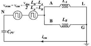
2003; Kjaer et al., 2005). The simplified equivalent model of
common mode leakage current has been derived is as shown in
fig. 1, Cpv is the parasitic capacitance, LA and LB are filter
inductors, icm is common mode leakage current.
Fig.1. Simplified equivalent model of common mode resonant circuit
As shown in the figure equivalent common mode voltage Vecm
is given by
= + (1)
where Vcm is the common mode voltage, Vdm is the
differential mode voltage, VAN and VBN are the output voltages
of the inverter relative to negative terminal N of the dc bus as common reference
= (2)
Vdm = VAB = VAN - VBN (3)
It is clear that common mode leakage current icm is excited by
Vecm. Therefore, the condition of eliminating the common
mode leakage current is that Vecm must be constant as follows
= +
2 +
= +
2 + 2 +
= constant (4)
When one of the filter inductor is made zero, then the condition for eliminating common mode leakage current is as follows,
= +
2 + 2 =
= constant (LA = 0) (5)
= +
2 2 =
= constant (LB = 0) (6)
As a result the constant common mode voltage can be achieved as
= =
= constant (LA = LB) (7)
ISPWM technique
The harmonics in the inverter can be eliminated using pulse width modulation (PWM) switching technique. In the conventional inverters the sinusoidal PWM is used in which sine wave is the modulating wave and triangular wave is the carrier wave. But it inhibits poor performance with regard to maximum attainable voltage and power.
Thus the modulation strategy employed in the inverter is the ISPWM. In this technique, inverse sine wave is used as carrier wave. The ISPWM technique has better spectral quality and higher fundamental component compared conventional sinusoidal PWM. Also there is reduction in total harmonic distortion (THD). The pulses are generated when amplitude of the reference sine wave is greater than that of inverted sine
carrier wave (Gonzalez et al., 2007; Li Zhang et al., 2014;
Antony Raja Sekar and Arun Prasad, 2013). The total harmonic distortion for different values of switching frequencies is obtained and is found to be lesser than the conventional methods. By employing the ISPWM, it has been proved that the fundamental voltage is improved throughout the working range and is greater than the voltage obtained using conventional methods.
Novel h6 topology and its operation modes
In the novel, H6 topology the two switches are employed on the dc side of the inverter. It contain two extra switches on dc side, and new switch added forms a new current path and acts for purpose of reducing the conduction loss
Fig. 3. The proposed H6 topology
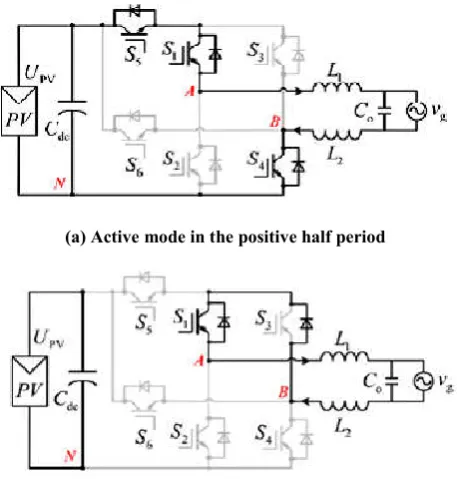
In the active modes of the H6 topology, the inductor current flows through two switches during one half line periods and through three switches during another half line switches. So, proposed H6 topology has minimum conduction loss as it uses five switches for the flow of leakage current.
(a) Active mode in the positive half period
b) Freewheeling mode in the positive half period
c) Active mode in the negative half period
d) Freewheeling in negative half period
Fig. 4. Equivalent circuits of operation modes of H6 Inverter
Mode I is the freewheeling mode in the negative half period,
voltage of the topology, VAB = VAN VBN. The CM voltage
VCM = 0.5(VAN +VBN). Mode I is the active mode in the
positive half period of the utility grid voltage, as shown in Fig.4 (a). S1, S4, and S5 are turned ON, and the other switches are turned OFF. The inductor current is flowing through S1,
S4, and S5. VAN = UPV, VBN = 0; thus, VAB = UPV, and the
CM voltage VCM = (VAN + VBN)/2 = 0.5UPV.
Mode II is the freewheeling mode in the positive half period of the utility grid voltage, as shown in Fig.4 (b). S1 is turned ON; the other switches are turned OFF. The inductor current is
flowing through S1 and the antiparalleled diode of S3. VAN =
VBN ≈ 0.5UPV; thus, vAB = 0, and the CM voltage VCM = (VAN
+ VBN )/2 ≈ 0.5UPV.
Mode III is the active mode in the negative half period of the utility grid voltage, as shown in Fig.4 (c). S2, S3, and S6 are turned ON; the other switches are turned OFF. The inductor current is flowing through S2 and S6. Although S3 is turned ON, there is no current flowing through it, and the switch S3 has no conduction loss in this mode. Nevertheless, in the H5 topology, the inductor current flows through S2, S3, and S5. Therefore, the conduction loss of proposed topology is less
than that of H5 topology. In this mode, VAN = 0, VBN = UPV;
thus, VAB = UPV, and the CM voltage VCM = (VAN + VBN)/2 =
0.5UPV. Mode IV is the freewheeling mode in the negative half
period of the utility grid voltage, as shown in Fig.4 (d). S3 is turned ON, and the other switches are turned OFF. The inductor current is flowing through S3 and the antiparalleled
diode of S1. VAN = VBN ≈ 0.5UPV; thus, VAB = 0, and the CM
voltage VCM = (VAN + VBN)/2 ≈ 0.5UPV. Based on the
aforementioned analysis, the PV array can be disconnected from the utility grid when the output voltage of the proposed H6 inverter is at zero voltage level and the leakage current path is cut off. The CM voltage of the proposed topology in
each operation mode is equals to 0.5UPV, and it results in low
SIMULATION AND RESULTS
The simulation of H6 inverter is carried out with ISPWM technique, which is as shown in figure below.
Fig. 5. Simulation of H6 inverter with ISPWM Technique
The harmonics in the output voltage of converters can be reduced using Pulse-Width Modulation (PWM) switching techniques. PWM methods reduce the harmonics by shifting frequency spectrum to the vicinity of high frequency band of carrier signal. In the case of sinusoidal PWM (SPWM) scheme, the control signal is generated by comparing a sinusoidal reference signal and a triangular carrier. The SPWM technique, however, inhibits poor performance with regard to maximum attainable voltage and power. The H6 inverter is with the ISPWM technique in simulink is developed, controlling both output voltage and frequency. For generation of PWM pulses the technique was used comparing sinusoidal control voltage (at the desired output frequency and proportional to the output voltage magnitude) with an inverted sine waveform at a selected switching frequency. A novel PWM technique, called Inverted-Sine PWM (ISPWM), for harmonic reduction of the output voltage is presented in. In addition, the control scheme based on ISPWM can maximize the output voltage for each modulation index. ISPWM switching technique has been developed for controlling of inverter which has lower Total Harmonic Distortion than conventional techniques.
Fig. 6. Simulink Model for ISPWM technique
The Fig. 6 shows the Simulink model for ISPWM technique. The inverted sinusoidal pulse-width modulation (ISPWM) technique produces a sinusoidal waveform by filtering an output pulse waveform with varying width. A high switching frequency leads to a better filtered sinusoidal output waveform. The desired output voltage is achieved by varying the frequency and amplitude of a reference or modulating voltage.
Fig. 7. THD of H6 inverter with ISPWM
Table I. Harmonic result analysis
Harmonic order ISPWM (3.98%) SPWM (6.21%)
DC 7.52 0.66
Fundamental 100 100
2 0.55 0.21
3 2.15 3.68
4 0.62 0.26
5 0.06 0.35
6 0.50 0.14
7 0.09 0.19
8 0.75 0.03
9 0.23 0.22
10 0.33 0.17
11 0.16 0.28
12 0.53 0.11
13 0.17 0.43
14 0.40 0.09
15 0.11 0.06
Fig. 8. Grid Voltage of the H6 inverter
Fig. 9. Grid Current of the H6 inverter
The variations in the amplitude and frequency of the reference voltage change the pulse-width patterns of the output voltage but keep the sinusoidal modulation. A low-frequency sinusoidal modulating signal is compared with a high frequency inverted sine, which is called the carrier signal. The switching state is changed when the sine waveform intersects the inverted sine waveform.
Conclusion
The improved grid connected inverter is presented in the paper. The inverter is implemented using novel ISPWM technique. The results are compared with SPWM. It is seen that the quality of output is greater in ISPWM than the SPWM. Also the THD of this novel technique is less than the other. Hence the H6 inverter with ISPWM technique can be the better solution for single phase grid connected systems.
REFERENCES
Antony Raja Sekar, R. and D. Arun Prasad "Improved Transformerless inverter for PV grid Connected Power
System by using ISPWM Technique."International
Journal of Engineering Trends and Technology
(IJETT),Volume 41, no. 5,pp. 1512-1517, May 2013.
Benner J. P. and L. Kazmerski, “Photovoltaics gaining greater
visibility,” IEEE Spectrum, pp. 34–42, Sept. 1999.
Blaabjerg, F., Z. Chen, And S. B. Kjaer “Power Electronics As Efficient Interface In Dispersed Power Generation
Systems,” IEEE Trans. on Power Electronics, Vol. 19, no.
5, pp. 1184–1194, Sep. 2004.
Chen Z. and E. Spooner, “Voltage source inverters for
high-power, variable-voltage dc power sources,” Proc. Inst.
Elect. Eng., vol. 148, no. 5, pp. 439–447, Sept. 2001.
Gonzalez, R., J. Lopez, P. Sanchis and L. Marroyo, “Transformerless Inverter for Single-phase Photovoltaic
Systems,” IEEE Transaction on Power Electronics., Vol.
22, No. 2, pp. 693–697, Mar. 2007.
Kjaer, S. B., J. K. Pederson, And F. Blaabjerg, “A Review Of Single-phase Grid-connected Inverters for Photovoltaic
Modules,” IEEE Transaction on Ind. Appl., Vol. 41, No. 5,
pp. 1292–1306, Sep/Oct. 2005.
Li Zhang, Kai Sun, Member, Yan Xing and Mu Xing “H6
Transformerless Full-Bridge PV Grid-Tied Inverters”IEEE
Transactions on Power Electronics, Vol. 29, no.3, pp.
-1229 -1238, March 2014.
Madhuri Kshirsagar, Dr. P. J. Shah "A Review of the single Phase Transformer Less Full Bridge PV Grid Inverters"
International Journal for Scientific Research &
Development (IJSRD), Vol. 4, no. 02, 2016.
Madhuri Kshirsagar, Dr. P. J. Shah "Evaluation of Transformerless Inverters for Single Phase Photovoltaic
Systems "International Journal of Innovative Research in
Electrical, Electronics, Instrumentation and Control
Engineering (IJIREEICE), Vol. 4, no. 6, June 2016.
Mohan, N., T. M. Undeland, and W. P. Robbins, Power Electronics -Converters, Applications and Design, 3rd Ed. New York: Wiley, 2003.
Oscar Lopez, Francisco D. Freijedo, Alejandro G. Yepes, Pablo Fernandez- Comesana, Jano Malvar, Remus Teodorescu, and Jesus Doval-Gandoy, "Eliminating Ground Current in a Transformerless Photovoltaic
Application" IEEE Transaction on Energy Conversion,
Vol. 25, no.1, March 2010.
Twining E. and D. G. Holmes, “Grid current regulation of a three-phase voltage source inverter with an LCL input
filter,” IEEE Trans. Power Electron., vol. 18, no. 5, pp.
888–895, May 2003.