MATLAB Simulation and Analysis of
Nine-Level Inverter Using Different Schemes of
Sinusoidal PWM
Rajesh Kumar Ahuja1, Amit Kumar2
Department of Electrical Engineering, YMCA University of Science & Technology, Faridabad, India 1, 2
ABSTRACT: A Nine-Level Diode Clamped Inverter with Sinusoidal PWM technique is presented in this paper. Three Phase inverter is studied and simulated in MATLAB/SIMULNK. In this paper the inverter is controled with the Level Shifted scheme of Sinusoidal PWM i.e. Phase Diosposition (PD), Phase Opposition Displacement (POD) and Alternative Phase Opposition Displacement (APOD). The inverter is simulated for R-L load and THD for output waveforms is observed for differnt controlling schemes. The THD for the output waveforms is observed and the the technique with least THD is seleted for furhter simulations.
KEYWORDS:Diode Clamped, Multi-Level Inverters, PD, POD, APOD, THD and NPC.
I. INTRODUCTION
In recent years the Multi-Level Invertres are very popular for Industrial and powers system applications due to their advantages on Two-level inverters i.e. High Power rating, Low Harmonics so they give the higher effiency. The different topologies of Multi-Level Inverters are Neutral-point clamped (NPC) or Diode Clamped (DC) inverter, Flying capacitor inverter and Cascade inverter. As the level increases, NPC require more clamping diodes so the control of real power flow becomes very difficult. In flying capacitor inverter as the level increases, number of storage capacitors also increases hence they becomes bulky and costly; there are more switching losses in this topology.
The cascaded multilevel inverters have more advantages than other topologies, because it does not require any balancing capacitors and diodes. Cascaded inverters need separate DC sources for each H-Bridge, so there is no voltage balancing problem, but isolated DC sources are not readily available, this is the main drawback of this topology. In this paper Diode Clamped Inverter is studied for different control schemes and at different values of the Loads (R-L).
II. DIODECLAMPEDINVERTERS
The first invention in multilevel converters was the so-called neutral point clamped inverter. It was initially proposed as a three level inverter.
The main advantages and disadvantages of this topology are:
High efficiency for the fundamental switching frequency.
The capacitors can be pre-charged together at the desired voltage level.
III. SINUSOIDALPWM
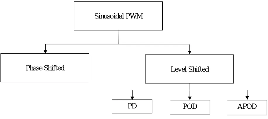
Control techniques for multilevel inverters are based on fundamental and high switching frequency. SPWM, SVPWM and SHE-PWM techniques are mostly used. The SPWM scheme is widely used due to many advantages i.e. simple implementation, low harmonic outputs compares to other schemes, and less switching losses. In SPWM scheme, a high frequency triangular signal is compared with a low frequency modulating signal to generate the control signals. The SPWM is further classified as Phase Diosposition (PD), Phase Opposition Displacement (POD) and Alternative Phase Opposition Displacement (APOD) and is shown in fig.1
Figures 2,3 and 4 shows these disposition techniques. Each of these variations has particular harmonic benefits.
SPWM
Figure: 1 Classification of Sinusoidal PWM
A. Phase disposition (PD) where all the carrier signals are in phase as shown in fig: 2
Figure 2: Phase Disposition (PD) for the Nine-Level DC-MLI
Sinusoidal PWM
Phase Shifted
Level Shifted
B. Phase Opposition Disposition (POD) where the carrier signals above the zero line of sinusoidal modulating waveform are 180 out of phase with those below the zero line as shown in figure: 3
Figure 3: Phase Opposition Disposition (POD) for the Nine-Level DC-MLI
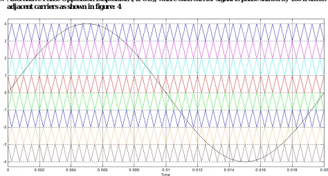
C. Alternative Phase Opposition Disposition (APOD), where each carrier signal is phase shifted by 180 from its adjacent carriers as shown in figure: 4
IV. SIMULATIONOFNINE-LEVELINVERTER
The simulation of Nine-Level Inverter is shown in Figure: 5 The inverter is realised by
Diode-Clamped Topology.
Figure: 5 Simulation of Diode-Clamped Nine-Level Inverter
V. SIMULATIONRESULTS
A. Results of Nine –Level Inverter using Phase Diosposition Scheme of SPWM
Nine-level inverter is simulated using PhaseDiosposition scheme and operated at different values of R-L load at 0.8 p.f. Output current, output voltage and Current THD is observed and shown in figures given below.
Figure: 6 Output Current at 1 KW of Phase Disposition (PD) Scheme
Figure: 7 Output Voltage at 1 KW of Phase Disposition (PD) Scheme
B. Results of Nine –Level Inverter using Phase Opposition Diosposition Scheme of SPWM
Nine-level inverter is simulated using Phase Opposition Diosposition scheme and operated at different values of R-L load at 0.8 p.f. Output current, output voltage and Current THD is observed and shown in figures given below.
Figure: 9 Output Current at 1 KW of Phase Opposition Disposition (POD) Scheme
Figure: 10 Output Voltage at 1 KW of Phase Opposition Disposition (POD) Scheme
C. Results of Nine –Level Inverter using Phase Alternative Opposition Diosposition Scheme of SPWM
Nine-level inverter is simulated using Phase Alternative Opposition Diosposition scheme and operated at different values of R-L load at 0.8 p.f. Output current, output voltage and Current THD is observed and shown in figures given below.
Figure: 12 Output Current at 1 KW of Alternative Phase Opposition Disposition (APOD) Scheme
Figure: 13 Output Voltage at 1 KW of Alternative Phase Opposition Disposition (APOD) Scheme
Table: 1
VI. CONCLUSION
Nine-Level Inverter is simulated using MATLAB. THD of current at different values of loads is observed using different Control Schemes of Sinusoidal PWM i.e. Phase Diosposition (PD), Phase Opposition Displacement (POD) and Alternative Phase Opposition Displacement (APOD).
THDs are analysed and summerized in Table 1. It is cleared from summery that THD for output current is Minimum for the PD scheme and maximum for APOD.
So it is clear from the simlation that the Phase Diosposition (PD) scheme is best suited for Diode-Clamped Multi-Level Inverter because this scheme produces least harmonis as compared to another two schemes hence the effenciency increases.
REFERENCES
[1] Calais, M.; Borle, L.J.; Agelidis, V.G., Analysis of multicarrier PWM methods for a single-phase five level inverter, Power Electronics Specialists Conference, PESC.2001 IEEE 32nd Annual, Volume 3, Issue , 2001. Pp :1351 – 1356.
[2] Leon M.Tolbert, Fang Zheng Peng, Thomas G.HabetJer, "Multilevel Converters for Large Electric Drives," IEEE Transactions on Industry Applications, vo1.35, no. I, pp.36- 44 January/February 1999.
[3] Johnson Uthayakumar R., Natarajan S.P., Bensraj R., “A Carrier Overlapping PWM Technique for Seven Level Asymmetrical Multilevel Inverter with various References” IOSR Journal of Engineering June. 2012, Vol. 2(6) pp: 1301- 1307
[4] Rajesh Kr Ahuja, Lalit Aggarwal, Pankaj Kumar “Simulation of Single Phase Multilevel Inverters with Simple Control Strategy Using MATLAB”, International Journal of Advanced Research in Electrical, Electronics and Instrumentation Engineering, Vol. 2, Issue 10, October 2013.
[5] D.G. Holmes, T. A. Lipo,” Modern Pulse Width Modulation Techniques for Power Converter”, IEEE Press, 2003
[6] Martha Calais, Lawrence J.Borlel Vassilios G. Agelidis “Analysis of Multi carrier PWM Methods for a single phase five level inverter” IEEE Transaction on Power electronics , July 2001,pp 1351-1356
[7] Leon M. Tolbert and Thomas G. Habetler “Novel multilevel inverter carrier based PWM method” IEEE Transaction On Industry Application Vol 35 No 5 Sep 1999 pp 1098-1107
[8] Rajesh Kumar Ahuja, Amit Kumar “Analysis, Design and Control of Sinusoidal PWM Three Phase Voltage Source Inverter Feeding Balanced Loads at Different Carrier Frequencies Using MATLAB” in IJAREEIE, Volume 3, Issue 5, May 2014.
[9] Zainal Salam1 and Junaidi Aziz, “Derivation of Switching Angles of the Cascaded Multilevel Voltage Source Inverter Subjected to a New Pulse Width Modulation Scheme”, the Institution of Engineers, Malaysia, Vol. 72, No.3, September 2009.
[10] J.S. Lai, and F.Z. Feng, “Multilevel converters–A new breed of power converters”, IEEE Transaction on Industrial Applications, Vol. IA-32, pp.509-517, May/June 1996.
[11] Rajesh Kumar Ahuja, Amit Kumar, “Analysis and Control of Three Phase Multi level Inverters with Sinusoidal PWM Feeding Balanced Loads Using MATLAB” IJERGS, Volume 2, Issue 4, June-July, 2014.
[12] Math Works, 2010, Sim Power Systems, User’s Guide. Load
Frequency 1 KW 3 KW 5 KW 7 KW 9 KW
PD Current 0.5208 1.557 2.69 3.623 4.654
THD 0.37 % 0.35 % 0.35 % 0.35 % 0.35 %
POD Current 0.521 1.557 2.591 3.624 4.655
THD 0.55 0.57 0.56 0.56 0.56
APOD Current 0.5219 1.559 2.595 3.629 4.662