5351
DESIGN OF HIGH VOLTAGE TRANSFORMER
USING FINITE ELEMENT METHOD
M.Leela Nivashini, K.Madhumitha, S.Sindhu, Dr.R.V.MaheswariAbstract—: A transformer is a static device that is mainly used for stepping up and down the voltage level. The Power transformer is a kind of transformer that is used to transfer electrical energy in any part of the electrical circuit between the generator and the distribution primary circuits. These transformers area unit employed in distribution systems to interface intensify and step down voltages. The transformer is important in transmission and distribution hence their testing is also essentially equal. The cost of a high voltage transformer is too high and also unavoidable equipment in that domain, hence it has to be designed properly before implementation in real-time. Simulating the transformer with the designed parameters will give the same results as in the real model. So it is easy for analyzing the EF distribution and calculating the losses and that can be easily avoided while implementing in real-time. The simulation of a three-phase 11/0.4 KV power transformer using the Finite Element Method is carried out in this project. Index Terms— Power transformer, Losses
—————————— ——————————
1 INTRODUCTION
Electrical device could be a passive device that transfers electricity between 2 or a lot of circuits. Current in the primary winding produces magnetic flux, this in turn creates variable EMF in the secondary winding of the same electrical device. Without any metallic contact electrical energy is transmitted between two coils as shown in Figure.1. By faradays law of electromagnetic induction induced voltage has impact on the coil in accordance to the dynamic magnetic flux encircled by the coil. Transformers are used for step up and step down in the AC voltage in electrical power applications and also for coupling the various stages in signal processing circuits. Transformers have become essential for the distribution, transmission, and utilization of alternating current electric power, due to the invention of the primary constant potential in electrical device [2]. Wide varieties of electrical device styles is confront in electronic and electrical power applications. Transformers point size from RF transformers but a cc in volume, to unit’s advisement many tons wont to interconnect the ability grid.
Fig. 1. Transformer circuit.
2
POWER
TRANSFORMER
2.1 DESCRIPTION
Using inductive coupling method, energy is transfer from one circuit to another in power electrical devices. Power electrical devices differ from different transformer sorts in this they're designed in such a way that they go with regulative necessities for mains power interfacing, performing at mains voltages and comparatively high currents. The foremost necessary specification of an electrical device is its primary to secondary winding galvanic isolation which is specified in terms of kV [3]. This can be a basic safety side in protective against deadly earth fault conditions. Power transformers usually have one mains side winding and one or more field windings. The field coil could also be introduced at totally different points to yield multiple voltage outputs. An influence electrical device works in accordance with Faradays Law of Electromagnetic Induction. A transformer’s secondary voltage is capable of producing abundant magnetic flux in the circuit is caused by the AC flowing within the primary. The dynamic flux produced by the AC couples the secondary coil through a standard core [4]. The voltage quantitative relation is adore the winding flip quantitative relation. Transformers square measure extraordinarily economical once operational at intervals their style specifications. The core sort is a very important thought. Typical power electrical device provides embody laminated core, semi-solid and solid. Laminations are used to resist the eddy currents flowing within the core that in turn cause loss of potency [5]. Whenever the core is saturated or the windings current rating is exceeded the output current is specified to the maximum. The mounting choices for square measure consist of chassis mount, DIN rail, wall mount and PCB mount. Terminations consist of solder lugs, wire leads and terminal blocks. Galvanic isolation range is from 0.5kV and 5kV.
2.2 TRANSFORMER CONSTRUCTION
In a transformer electrical windings are coupled together by a magnetic field. The coupling is increases with increase in force of magnetic core in special-purpose transformers. Transformers are not built in a way that they are with the ————————————————
Ms.M.Leela Nivashini is studying final year Electrical and Electronics Engineering in National Engineering College, India, E-mail:
Ms.K.Madhumitha is studying final year Electrical and Electronics Engineering in National Engineering College, India, E-mail:
Ms.S.Sindhu is studying final year Electrical and Electronics Engineering in National Engineering College, India, E-mail:
5352 primary coil on one arm and the secondary coil on the other
arm. Primary winding induces the magnetic flux when an AC voltage is supplied, which in turn induces voltage in the secondary. The secondary winding induces a sinusoidal voltage whenever the flux is curve. The primary is connected to the source (generator), and the secondary is connected to the load. High-voltage or low-tension facet is available. The magnetizing current is minimized by constructing core with low reluctance material [6]. The core is made of laminations in order to reduce eddy current losses, the rated frequency of the transformer is inversely proportional to thickness of the core. The lamination thickness squared is directly proportional to Eddy current losses. Thus, the eddy current losses are reduced to 75% by halving the thickness; however, the cost of the core decreases with increasing lamination thickness [7]. The cost of building the core must be compensating against the cost of the losses. Silicon steel laminations are used for 60 Hz operation, with thicknesses of 0.010″ to 0.020”. The wound ribbon is used for very high-frequency operation. The laminations must be insulated from each other for the flow of eddy current [8]. The insulation may be nothing more than the oxidation on the surface of the lamination. The flux density will be higher when the core is insulated than iron insulation. These factors are calculated as stacking factor. Stacking factor is used to measure the percentage of cross sectional area of the iron. The stacking factor is ranges above 0.9 for 60 Hz operation. Stacking factor decreases with decrease in lamination thickness.
2.3 TRANSFORMER CORE
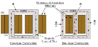
Transformer is an electrical device that steps up or steps down the electrical voltage. It consists of two windings i.e., primary and secondary windings are wound round the central laminated steel core. The two most typical and basic type of core construction in transformer are the closed-core and shell type core. In Closed-core type, the primary and secondary windings are wound outside and surround the core ring. In Shell type core, the secondary windings pass inside the steel magnetic circuit (core) which forms a shell around the windings as shown in Fig.2.
Fig. 2. Basic core construction
The magnetic flux linking the primary and secondary windings travel through the core with no losses. In transformer magnetic circuit primary and secondary windings are wound around each limbs of electrical devices as shown above. The coils arranges in such a way that half of the first winding and half of the secondary winding are placed one above the another in concentric manner so that the magnetic lines of forcers are equal in both the winding . Leakage flux is nothing but the small amount of magnetic lines of force flows outside the core in electrical device
construction In order to reduce the leakage flux in the primary and secondary winding, shell sorts are used since cross sectional space between two limbs are doubled. Shell sort has the advantage that, before reaching the center coil the magnetic flux flows in two ways from external to coils on primary and secondary windings. In this type of transformer construction the magnetic flux circulating the outer limbs of is equal to Φ/2. Whenever the magnetic flux induced in a closed path the magnetic core losses is decreases and overall potential of the transformer increases.
2.4 WINDING
Depending upon applying of electrical field, electrical current passes through all the conductors of the windings and each turns are insulated around each other. The magnetic wire coil wound is used for small transformer with low current and low voltage applications. Oil-impregnated paper and blocks of pressboard used for wind larger power transformers wrapped with copper strips. In order to reduce the skin effect and losses in high frequencies transformer litz wires are used for winding. Even at low power frequencies power transformers with multiple-stranded conductors used in non-uniform distribution and high current applications. Windings are equally insulated with the single strand so that entire portion is occupies by different relative positions in the conductor. Each and every strands is equalizes by transposition in order to reduce the eddy current losses in the winding. In manufacturing process stranded conductors are more flexible than a solid conductor.
2.5 WORKING PRINCIPLE AND OPERATION
The main operation principle of a transformer is coefficient of mutual induction between two circuits that is joined by a magnetic flux. A basic transformer consists of primary and secondary windings which are electrically isolated but magnetically connected through a path of reluctance. The core is made up of laminated sheets in order to eliminate o reduce the eddy current loss in the transformer. These laminated sheets are joined through the staggered joints in order to avoid the pursuance of normal air gap right through the cross sections. These staggering joints are said to be 'imbricated'. Both the coils have high mutual inductance. If one of these coils is connected to the source of alternating voltage, a mutual EMF will be induced in another coil. This can be explained by the Faradays law of mutual induction.
3
DESIGN
OF
TRANSFORMER
3.1 DESIGN PARAMETERS IN TRANSFORMER These parameters are split into seven types
Description variables (e.g., rated power, rated low voltage (LV) and high voltage (HV), frequency, LV and HV connection).
Special variables (core stacking factor, the mass density of materials used).
Default variables (e.g., LV and HV taps, guaranteed a no-load loss, load loss, and impedance voltage).
Cost variables (e.g. Unit cost of Material).
Various. variables (e.g. No’s of HV & LV Ducts)
5353
Design variables. (E.g. Leg center, Window height, LV turns)”.
3.2 STEPS FOR DESIGNING TRANSFORMER a. Calculation of Number of Turn
Based on kVA rating EMF per turns is calculated. So, EMF per turns is calculated using an equation
EMF per turn, 𝐸 = 𝑘√Q Where Q=Power rating
The numbers of primary and secondary turns are calculated as follows,
No of turns in primary, 𝑇 = 𝑉 /𝐸 No of turns in secondary, 𝑇 = 𝑉 /((√3 ∗ 𝐸)
Where, 𝑉 ,𝑉 is voltage in primary and secondary winding respectively.
b. Core Design
Core design includes the calculation of area, diameter, and several steps of the core. This design is based on frequency, flux density and EMF per turns.
Flux in the core, ɸ = 𝐸/(4.44 ∗ 𝑓) Net iron area, 𝐴 = ɸ /B
c. Winding Design
There are two types of winding designs: (i) HV winding. Design and (ii) LV winding design. To design a winding, rated current, cross-sectional area, number of a disc, tapping disc, turns per. disc, radial depth, axially shrunk height, and shrunk height, inner and outer diameter is calculated. Some standard constant values are required to design winding.
Secondary phase current,I = 𝑄/(3 ∗ V ) Area of secondary conductor, A = I /δ Axial depth of LV winding,
L = turns ∗ axial depth of conductor Radial depth of LV winding,
B = No. of layers ∗ Radial depth of conductor
Resistance of primary winding= (𝑇 *ρ*length of primary winding)/ (A )
Similarly calculation is being done for the HV winding.
4
MODELLING
OF
TRANSFORMER
USING
FINITE
ELEMENT
METHOD
4.1 ANSYS MAXWELL
ANSYS, Inc. is a yank Computer-aided engineering package developer that publishes engineering analysis package across a spread of disciplines like finite part analysis, structural analysis, procedure fluid dynamics, explicit/implicit ways, and warmth transfer. ANSYS Maxwell as a superior, low-frequency magnetic force field simulation interactive package. ANSYS Maxwell uses finite part analysis (FEA) method to resolve magnetic force issues by resolution Maxwell's equations in an exceedingly finite region of space with appropriate boundary and user-specified initial conditions. Maxwell uses the correct finite part technique to resolve static, frequency-domain, and time-varying electromagnetic and electric fields.
The magnetic force field are given by James Clerk Maxwell as physical equations which are as follows:
• Gauss’ Law for Electricity 𝛁.𝑫=𝒑
• Gauss’ Law for Magnetism 𝛁.𝑩=𝟎
• Faraday’s Law of Induction 𝛁 ×𝑬= −𝝏𝑩/𝝏𝒕 • Amperes’ Law 𝛁 ×𝑯=𝑱 + 𝝏𝑫/𝝏𝒕
With this software package, the non-linear, transient motion of electromechanical devices can be characterized and their effects can be predicted. It is widely used in industries as a simulation technology in performance analysis of the electromechanical system and hence building a prototype.
4.2 ANSYS RMXPRT
(RMxprt) Rotating Machine Expert is a template-based design tool that help to easily evaluate the design trades -off early in the process. It enables the customized designing of the machines to meet the demand of higher efficiency. The main advantage of this tool is that it has the ability to automatically generate the entire design set -up in 2D/3D including the geometry, materials and also boundary conditions. The set up includes the appropriate symmetries and excitations with coupling circuit topology for electromagnetic transient analysis. The major advantages of using this ANSYS Maxwell software are:
• Industry Leading Low-Frequency Electromagnetic Field Simulation.
• High-Performance Design Delivery. • High Fidelity, Model-Based Design.
2-D/3-D vector hysteresis modeling in ANSYS Maxwell is applicable for each soft and arduous magnetic materials. Maxwell second may be a superior interactive package that uses finite component analysis (FEA) to resolve electrical, magneto static, eddy current, and transient issues. There are six solvers available in Maxwell 2D. They are:
• Electrostatic.
• AC Conduction Electric Fields. • DC Conduction.
• Magneto static.
• Eddy Current Magnetic Fields. • Transient Magnetic.
4.3 SYSTEM REQUIREMENTS
All the simulations were done using ANSYS Workbench and the last version of Maxwell, 19.2 and a personal computer with the following characteristics.
• CPU: Intel Core i5 6th generation.
• RAM: 8GB
• Hard Disk Space: 1 TB
4.4 FINITE ELEMENT METHOD (FEM)
To resolve the issues of engineering and mathematical physics the numerical technique such as finite part technique (FEM) plays a vital role. The drawback of structural analysis, heat transfer, fluid flow, mass transport, and magnetism potential. In partial differential equations the solutions for boundary values are met out by analytical solution. The subdivision of a full domain into less complicated components has many benefits.
5354 • Representation of the total solution
• The capture of local effects.
Known as Finite Element Analysis (FEA) is suitable for practical application, to understood FEM method [15]. For activity engineering analysis FEA is used as process tool for engineering analysis. It includes the employment of mesh generation techniques for dividing a posh drawback into little parts, additionally because the use of package program coded with FEM rule. FEA is a best choice for analyzing problems in complicated domains, when the domain changes or required preciseness varies over the domain, or the answer will lacks its smoothness.
5
EXPERIMENTAL
RESULTS
5.1THEORETICALLY DESIGNED PARAMETERS
The 3 phase power transformer is experimentally tested with the help of these design parameters are given in Table 5.1
Table 5.1 Designed parameter
PARAMETER VALUE
Frequency 50Hz
Rated voltage 11/0.44 KV
Rated current 315/7860 A
Number of turns 400/16
EMF per turn 9.607 Volt/turn
Area of iron core 0.0255 𝑚
Number of primary turns per phase 1145 Number of secondary turns per phase 25 Resistance of primary winding 1876 Ω Resistance of secondary winding 49 Ω
The above mentioned design parameter values of 3 phase power transformer are derived and calculated using appropriate formulae.
5.2
S
IMULATION OBTAINED BYF
INITEE
LEMENTM
ETHODUSING
ANSYS
S
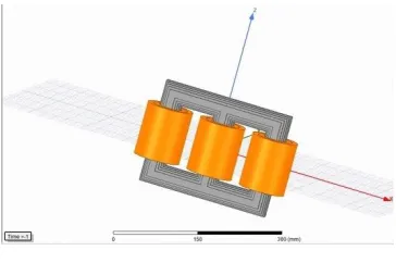
OFTWAREUsing the values form Table 5.1, the three phase power transformer was designed and stimulated by Finite Element Method using ANSYS software.
Fig. 3. Basic core construction
The 3-D model is computed in ANSYS with the designed values shown in the Fig .3. This 3-D stimulated model is cost
effective when compared to real time experimental set up. This 3-D model analysis helps to verify the losses occurs in real time.
6
RESULT
AND
DISCUSSION
The three-phase power transformer with the rating of 11/0.4 kV was designed by considering certain parameters such as type of the material used for core, the lamination on the core, window dimensions, the type of the winding such as helical, disc and cylindrical, the material used for winding, number of turns in primary and secondary winding, the resistance in the windings, the frequency range for operation etc., The designed transformer model is simulated in the ANSYS software.
7
CONCLUSION
A simulation is an approximate imitation of the operation of a process or system that represents its operation over time. This is used for obtaining the optimized model. In this project, three-phase power transformer was designed by the conventional formulas and simulated the model using ANSYS software.
REFERENCES
[1] https://www.instructables.com/id/Three-Phase
Transformer-Design Using-Ansys-Maxwell/ Design of Three phase transformer using ANSYS.
[2] Design Methodology of Power Transformer CHAPTER 4: DESIGNMETHODOLOGY OF POWER TRANSFORMER [3] Dawood " A new method for the calculation of
leakage reactance in power transformers", J. Elect. Eng. Technol., vol. 12, no. 5, pp. 1883-1990, 2017. [4] Gäfvert, Adeen, Tapper, Ghasemi, Jönsson,
"Dielectric Spectroscopy in Time and Frequency
Domain Applied to Diagnostics of Power
Transformers", Proc. Of the 6th ICPADM, Xi' an, China, 2000.
[5] Jamali, Mirzaie and Asghar Gholamian, “Calculation and analysis of transformer Inrush current based on parameters of transformer and operating conditions”, Electronics and Electrical Engineering – Kaunas: Technological, no. 3 (109). , pp. 17-20-2011.
[6] Kashtiban, "Finite Element Calculation of Winding Type Effect on Leakage Flux in Single Phase Shell Type Transformers", Proceedings of the 5th WSEAS International Conference on Applications of Electrical Engineering, pp. 39-43, March 12-14, 2006.
[7] Susa, “Dynamic thermal modeling of power transformers”, Ph.D. dissertation, Dept. of Electrical and Communications Eng., Helsinki Univ. of Technology, 2005.
[8] Werelius " Diagnosis of Medium Voltage XLPE Cables by High Voltage Dielectric Spectroscopy" paper presented at ICSD 1998.
[9] Sarac V. Faculty of Electrical Engineering, University “Goce Delcev”, R. Macedonia,” fem 2d and 3d design of transformer for core losses computation” Industry 4.0 Vol. 2 , Issue 3, pg.(s) 119-122-2017.
5355 [11]Kassim, R. Hameed. "Analysis of Short-Circuit Forces in
Windings of Shell-Type Wound Core Distribution Transformer Using Finite Element Method Ph.D. Thesis, University of Technology, 2007.
[12]David Ribbenfjard, "Electromagnetic Transformer Modeling Including the Ferromagnetic Core'', Ph.D. Thesis, Stockholm, Sweden, 2012.
[13]Waleed A. Baddai, Two-Dimensional Nonlinear Finite Element Modeling Of A Single Phase Transformer", M.Sc. Thesis, University of Technology, 2004.
[14]Hernández1,I. J. M. Cañedo, J. C. Olivares-Galván and P.S.Georgilakis, Electromagnetic Analysis and Comparison of Conventional-Wound Cores and Octagonal-Wound Cores of Distribution Transformers”, Materials Science Forum Vol. 670 pp 477-486, Vol.4, No.2, pp. 155-164,Switzerland, 2011.