384
Cost Effective Power Factor Measurement Using
Microcontroller ATmega8
Chandam Thoisana Singh
Abstract: This paper presents a simple, cost effective and accurate power factor measurement system implemented using ATmega8 microcontroller. In the present technological revolution power is very precious. So we need to find out the causes of power loss and improve the power system with a suitable method. Nowadays most of the product are developed with microcontroller based embedded technology. The use of microcontroller reduces the cost.
Index Terms: power factor measurement, zero crossing detector, power triangle, lagging and leading power factor, microcontroller ATmega8, circuit design, result and characteristics analysis.
————————————————————
1
I
NTRODUCTIONIn the present scenario of technological revolution, it has been observed that the power is very precious. The industrialization is primarily increasing the inductive loading; the inductive loads affect the power factor so the power system losses its efficiency. There are certain organizations developing products and carrying R&D work on this field to improve or compensate the power factor. In the present trend the designs are also moving forwards the miniature architecture; this can be achieved in a product by using programmable device. Whenever we are thinking about any programmable devices then the embedded technology comes into front. The embedded technology is nowadays much popular and most of the product are developed with microcontroller based embedded technology. The advantages of using the microcontroller is the reduction of cost and also the use of extra hardware such as the use of timer, RAM and ROM can be avoided. This technology is very fast so controlling of multiple parameters is possible; also the parameters are fields programmable by the user. The electrical engineering and its application are the oldest streams of engineering. Though these systems are quite reliable and cheaper, it has certain disadvantages. The electromechanical protection relays are too bulky and needs regular maintenance. The multifunctional is out of question. Recently, the technical revolution made embedded technology cheaper, so that it can be applied to all fields. The pioneer manufacturers of power system and protection system such as SIMENS, LARSON & TOUBRO, and CUTLER HAMPER etc. manufacturing power factor improvement devices on the embedded technology. The power factor measurement device is a very useful device for improving efficient transmission of active power. If the consumer connects inductive load, then the power factor lags, when the power factor goes below 0.97(lag) then the electric supply company charge penalty to the consumer. So it is essential to maintain the power factor below within a limit.
2
Basics of Power Factor
When we apply AC voltage to resistive loads it will not change the current waveform. But the inductive loads will force to lag the current waveform and in the case of capacitive loading it will force to lead the current waveform than voltage waveform. We can see the waveforms of inductive load. The phase shift of 30 degree is present in the current waveform.
Fig.1 Inductive Load waveform
The power factor is basically the “angle cosine of that lagging current”. In simple words, current is lagging by voltage with some angle and if take the cosine of that angle we will get the power factor. In other words, power factor is a ratio of real or active power and apparent power. Many inductive loads are used in power system. Inductive loads need reactive power for their proper operation. So main cause of power factor in electrical power system is reactance, capacitors provide reactive power. In other words, capacitors generate reactive power and inductors consume reactive power.
————————————————
385 Fig. 2(a) Power Triangle
If somehow we can measure the time difference of both waveforms then we can find our required angle by using the formula below.
All current will cause losses in the supply and distribution system. A load with a power factor of 1.0 result in the most efficient loading of the supply and a load with a power factor 0.5 will result in much higher losses in the supply system. A poor power factor can be result of either a significant phase difference between the voltage and current at the load terminals, or it can be due to a high harmonic content of distorted/discontinuous current waveform. Poor load current phase angle is generally the result of an inductive load such as an induction motor, power transformer, lighting ballasts, welder or induction furnace. A distorted current waveform can be the result of a rectifier, variable speed drive, switched mode power supply, discharge lighting or other electronic load. A poor power factor due to an inductive load can be improved by the addition of power factor correction, but a poor factor due to a distorted current waveform requires a change in the equipment design or expensive harmonic filters to gain an appreciable improvement. Many inverters are quoted as having a power factor of better than 0.95 when in reality, the true power factor is between 0.5 and 0.75. The figure of 0.95 is based on the cosine of the angle between the voltage and current but does not take into account that the current waveform is discontinuous and therefore contributes to increased losses in the supply.
Increasing the power factor:
Fig. 2(b)
As the power factor (i.e. Cos Ө) increases, the ratio of the real power to apparent power (which=Cos Ө), increases and approaches unity (1), while the angle Ө decreases and the
reactive power decreases. [As Cos Ө →1, its maximum possible value, Ө→0 and so Q→0, as the load becomes less reactive and more purely resistive].
Decreasing the power factor:
Fig. 2(c)
As the power factor decreases, the ratio of real power to apparent power also decreases, as the angle Ө increases and reactive power increases.
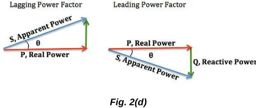
Lagging and leading power factor:
There is also a difference between a lagging and leading power factor. The terms refer to whether the phase of the current is lagging or leading the phase of the voltage. A lagging power factor signifies that the load is inductive, as the load will consume reactive power, and therefore the reactive component Q is positive as reactive power travels through the circuit and consumed by the inductive load. A leading power factor signifies that the load is capacitive, as the load supplies reactive power, and therefore the reactive component Q is negative as reactive power is being supplied to the circuit.
Fig. 2(d)
Zero cross detection:
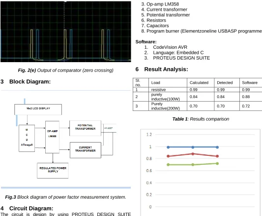
Zero cross detection is a method which can enable us to measure the time between voltage and current. In this technique we get a high value (i.e. 1) whenever a zero will cross the system. There are many ways to implement it. But this technique is the heart of this paper. In this paper we implemented zero crossing using LM358 an 8pin IC having dual amplifiers in it. In zero crossing, we have to get a “high” value during crossing of zero in waveforms. So to get that value we use amplifier as a comparator which will compare the non-inverting reference value and then act accordingly. The output of the comparator is given in fig.2(e) in which yellow is the output of voltage and blue is the output of current having some lag.
386 Fig. 2(e) Output of comparator (zero crossing)
3
Block Diagram:
Fig.3 Block diagram of power factor measurement system.
4
Circuit Diagram:
The circuit is design by using PROTEUS DESIGN SUITE software.
Fig.4 Simulation diagram for power factor measurement system.
5
Components Required:
Hardware: 1. ATmega8
2. LCD display(16x2)
3. Op-amp LM358 4. Current transformer 5. Potential transformer 6. Resistors
7. Capacitors
8. Program burner (Elementzoneline USBASP programmer)
Software:
1. CodeVision AVR 2. Language: Embedded C
3. PROTEUS DESIGN SUITE
6
Result Analysis:
Sl.
no. Load Calculated Detected Software
1 resistive 0.99 0.99 0.99
2 purely
inductive(100W) 0.84 0.84 0.88
3 Purely inductive(200W) 0.70 0.70 0.72
Table 1: Results comparison
Fig. 5 Characteristics analysis
7 Advantage of Improved Power Factor:
1. Decreasing reactive power2. Avoid poor voltage regulation 3. Overloading is avoided 4. Decreasing copper loss 5. Decreasing transmission loss 6. Improved voltage control
7. Increasing efficiency of supply system and apparatus
387 //LCD
#define RS PORTD.6 #define E PORTD.7 unsigned char t1,z1;
void loops();
void setPortD0(int x); void setPortD1(int x);
unsignedint k=0,x=0,g=0; floatpf=0;
unsigned char buf[10]; void loops()
{ while(1) {
if (PINC.4==1) {
TCNT1=0;
TCCR1B=0x01;//Start timer at Fcpu/1
break; } else { continue; } if (PINC.5==1) {
TCCR1B=0x00; g=TCNT1; break:
} else { continue; } } }
void setPortD0(int x) {
PORTD.0=1; delay_ms(x); PORTD.0=0; }
void setPortD1(int x) {
PORTD.1=1; delay_ms(x); PORTD.1=0; }
//………..Begin LCD
Code………..
intlcd_data(char t) {
RS=1; PORTB=t; E=1; delay_ms(1); E=0; delay_ms(1);
t1=t<<4; PORTB=t1; E=1; delay_ms(1); E=0;
delay_ms(1); return 0; }
intwritecmd(char z) {
RS=0; PORTB=z; E=1; delay_ms(1); E=0; delay_ms(1); z1=z<<4; PORTB=z1; E=1; delay_ms(1); E=0; delay_ms(1); return 0; }
voidlcd_print(char*str) {
unsigned char i=0; while (str[i]!=0) {
lcd_data(str[i]); i++;
} }
voidlcd_init(void) {
writecmd(0x02); writecmd(0x28); writecmd(0x0c); writecmd(0x01); writecmd(0x06); }
voidlcd_gotoxy(unsigned char x, unsigned char y)
{
unsigned char firstcharadrs[]={0x80,0xC0,0x94,0xD4};
writecmd(firstcharadrs[y-1]+x-1); delay_us(100);
}
//__________End of LCD code____________
//Power Factor Function intpowerfactor()
{ k=0;
//To complete number of counts g=g+1;
388 pf=(float)g/1000000;
//To convert into radians pf=pf*50*360*(3.14/180); pf=cos(pf);
k=abs(ceil(pf*100)); return k;
}
void main(void) {
//Input/Output Ports initialization
DDRC=0x03; DDRB=0xff; DDRD=0xff;
//______LCD Initialisation________ lcd_init();
lcd_gotoxy(1,1);
lcd_print(“Power Factor”); while(1)
{ loops();
setPortD0(5); //delay time setPortD1(3);
x=powerfactor(); //delay_ms(10); itoa (x,buf);
lcd_gotoxy(1,2); lcd_print(buf); lcd_print(”%”); } }
9 Conclusion:
It can be concluded that power factor measurement techniques can be applied to the industries, power systems and also households to make them stable and due to that the system becomes stable and efficiency of the system as well as the apparatus increases. The use of microcontroller reduces costs. Due to use of microcontroller multiple parameters can be controlled and the use of extra hardware such as timer, RAM, ROM and input output port reduces. Care should be taken for overcorrection otherwise the voltage and current becomes more due to which the power system or machine becomes unstable and the life of the capacitors banks reduces.
References
[1] S.B. Jamge, “Automatic Power Factor Correction using PSoC3”,International Journal of Engineering Research & technology, Vol.3,pp. 1056-1058, May 2014.
[2] Peter D. Hiscocks, “Measuring AC Current and Power Factor”, Syscomp Electronic Design Limited, Application Note, July 17, 2013.
[3] B Dieme and W Badenhorst, “Multiplug Energy Meter with Control and Protection”, International Journal of Electrical power and Energy System, Vol. 5, pp. 543-548, 2009.
[4] Kuhendran, “Power Meter using AVR microcontroller”, UG Thesis, universiti Teknologi, Malaysia, 2012. [5] Sabir Rustemli, Muhammed Ates, “Measurement and
Simulation of Power factor using PIC16F877”, ISSN
0033-2097, R. 88 NR 6/2012.
[6] Power factor measurement using
Atmega8/16|Engineer Experiences
http://engineerexperiences.com/power-factor-measurement.html
[7] Jill C. Duplesis, “Understanding Limitations of a Traditional power factor Measurement and its Analysis”, Application note, OMICRON electronics corp ., USA., 2012.
[8] Md. Rifat Shahriar, Ui-Pil Chong, “Design of a Power Factor Measurement System for Nonlinear Load”, Journal of the Korean Institute of Illuminating and Electrical Installation Engineers (2011) 25 (11): 113 ̴̴ 122.
[9] IEEE working Group on Non sinusoidal Situations: Effects on Meter Performance and Definitions of powers, “Practical definitions for powers in systems with non sinusoidal waveforms and unbalanced loads: a discussion,”, IEEE Transactions on Power Delivery, Vol.11, no.1, pp.79-101, January 1996.
[10] ArindhamBiswas,SurjitDhar,AshokeKumarBasu,Amar nathSanyal “Power Factor Measurement and Correction using Digital controller Implemented on FPGA”, International Journal of Microelectronics Engineering (IJME), Vol.1, No.1, 2015.