http://www.sciencepublishinggroup.com/j/ajsea doi: 10.11648/j.ajsea.20170602.18
ISSN: 2327-2473 (Print); ISSN: 2327-249X (Online)
Determination of Diffraction Loss over Isolated Doubled
Edged Hill Using the ITU-R P.526-13 Method for Rounded
Edge Diffraction
Ogungbemi Emmanuel Oluropo
1, Ikechukwu H. Ezeh
2, Chibuzo Promise Nkwocha
31
Department of Electrical/Electronic and Computer Engineering, University of Uyo, Uyo, Nigeria
2Department of Electrical Engineering, Imo State University (IMSU), Owerri, Nigeria 3
Department of Chemical Engineering Federal University of Technology, Owerri (FUTO), Owerri, Nigeria
Email address:
[email protected] (C. P. Nkwocha)
To cite this article:
Ogungbemi Emmanuel Oluropo, Ikechukwu H. Ezeh, Chibuzo Promise Nkwocha. Determination of Diffraction Loss over Isolated Doubled Edged Hill Using the ITU-R P.526-13 Method for Rounded Edge Diffraction. American Journal of Software Engineering and Applications.
Vol. 6, No. 2, 2017, pp. 56-60. doi: 10.11648/j.ajsea.20170602.18
Received: January 8, 2017; Accepted: January 18, 2017; Published: June 12, 2017
Abstract:
In this paper, Recommendation ITU-R P.526-13 rounded edge diffraction loss method is used to determine the diffraction loss over a double edged hilltop in the path of 6 GHz C-band microwave signal. The computation is based on the path profile with path length of 6188.665 m. The path profile has maximum elevation of 412.75 m and it occurred at a distance of 2877.3 m from the transmitter. The line of sight clearance height is 35.393521m and occultation distance is 532.203m. The diffraction loss computed for the double edged hilltop using the Recommendation ITU-R P.526-13 model is 42.563065 dB.Keywords:
Diffraction Loss, Diffraction Parameter, Doubled Edged Hill, ITU-R P.526-13 Method, Rounded Edge Diffraction1. Introduction
In wireless communication system, as signal propagates along the path from transmitter to the receiver, it experiences reduction in signal strength which is generally referred to as path loss [1-5]. The path loss may include propagation losses caused by the natural expansion of the radio wave front in free space, absorption losses, as well as diffraction losses when part of the radio wave front is obstructed by an opaque obstacle [6-12]. In other to estimate the diffraction loss caused by isolated obstacles like hills, mountains, buildings, such isolated obstacles are modeled as single knife edge obstructions [13-15]. However, in reality, the obstruction presents more diffraction loss than the single knife edge approximation. In that case, rounded edge diffraction loss approximation may be applied to such isolated obstacles.
Over the years, several methods for determination of rounded edge diffraction loss have been developed. One of the popular approaches is a method to determine the excess diffraction loss above the knife edge diffraction loss. The access diffraction loss can be computed according to Hacking
method [1], [17]. Wait method is another method for computing the access diffraction loss in addition to the knife edge approximation [18], [19]. However, in this paper, the method presented by the International Telecommunication Union (ITU) for computing diffraction loss over single rounded obstacle is used to compute the diffraction loss over double edged hilltop [20].
method for rounded edge diffraction [20].
2. The ITU-R P.526-13 Method for
Diffraction over Single Rounded Edge
The diffraction loss for single rounded obstacle according to Recommendation ITU-R P.526-13 is given as follows [20]:
A ν T m, n (1) where:
J (ν) is the Fresnel-Kirchhoff loss due to an equivalent knife-edge placed with its peak at the vertex point. According to ITU –R 526, t he knife edge diffraction loss, J (ν) is given as;
J ν 6.9 20Log 0.1 1 0.1 (2)
v is the diffraction parameter. The diffraction parameter ν is
given as;
v "# $% &
' $ & (3)
where ʎ is the signal wavelength which is given as;
ʎ )* (4)
f is the frequency in Hz and c is the speed of light which is 3x10+ m/s.
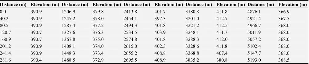
h is the line of sight (LOS) clearance which is obtained from the path profile and obstruction geometry, as shown in figure 2.
,- is distance from the transmitter to the point where the LOS clearance is measured, as shown in figure 2.
, is distance from the receiver to the point where the LOS clearance is measured, as shown in figure 2.
h and λ are in meters, and d1 and d2 are in kilometres.
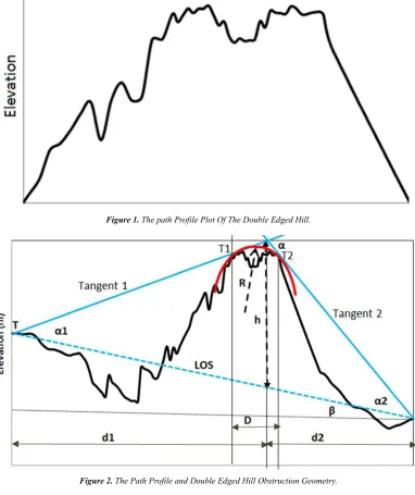
Figure 1. The path Profile Plot Of The Double Edged Hill.
T (m, n) is the additional attenuation due to the curvature of the obstacle and it is given as [20]:
T m, n dB = 7.2 1 -/ − 2 − 12.54 1 + 3.6 1 6/ −
0.8 1 89: 14 ≤ 4 (5)
T m, n dB = −6 − 20=9> 14 + 7.2 1 -/ −
2 − 174 1 + 3.6 1 6/ − 0.8 1 89: 14 > 4 (6)
Where,
m =@ A$ A&A$BA& C D
E
$/F (7)
4 =GC DE
H /6
(8)
The radius, I of the circle fitted in the vicinity of the double edged hill vertex can be given the expression (Seybold, 2005, Barué, 200);
I = J $ &
K L $ &% & &M (9)
where D is the occultation distance and it is obtained from the graph plot of the path profile and geometry of the obstruction, as shown in figure 2. Particularly, a line (referred here as tangent 1) is drawn from the transmitter to be tangential to the path profile at the vicinity of the hill apex. Let the tangent point of tangent 1 with the path profile be denoted as T1. Again, another line (referred here as tangent 2) is drawn from the receiver to be tangential to the path profile at the vicinity of the hill apex. Let the tangent point of tangent 1 with the path profile be denoted as T2. Then, D is the distance between T1 and T2. The point at which the tangent 1 and tangent 2 intersect above the hill vertex, as shown in figure 2.
becomes the knife edge point. The LOS clearance is the height from the line of sight to the point of intersection of tangent 1and tangent 2.
Let β be the angle the LOS makes with the horizontal where;
β = OP4Q- RSQRT
U (10)
where
HS is the height of the transmitter and HT is the height of the receiver and d is the distance between the transmitter and the receiver. The values of d, HS and HT are obtained from the path profile data.
d = d-+ d (11) Let α- be the angle (in radian) between the LOS and tangent 1 and let α be the angle (in radian) between the LOS and tangent 2 then, α is the external angle (in radian) between tangent 1 and tangent 2 at their point of intersection above the hill vertex, where
α = α-+ α (12) The angles α- and α are obtain by cosine rule as follows;
Cos α- = Z$ &% ZZ$F &ZQ ZF & & (13)
α-= CosQ- Z$ &% ZZ$F &ZQ ZF & & (14)
Similarly,
α = CosQ- Z& &% ZF &Q Z$ &
Z& ZF (15)
where
S- is the length of the tangent 1 measured from the transmitter to the point of intersection of tangent 1 and tangent 2, as shown in figure 2.
S is the length of the tangent 2 measured from the receiver to the point of intersection of tangent 1 and tangent 2, as shown in figure 2.
S6 is the length of the LOS measured from the transmitter to receiver
S-, S and S6 are in meter and they are measured out from the path profile plot and the tangent line drawn on the path profile.
The line of sight (LOS) clearance, h is given as;
h = Z$LZ]^ K$ M
Z]^ _`Qa (16)
3. Results and Discussions
The study if conducted for the L-band microwave frequency which ranges from 1 GHz to 2 GHz. Specifically, the 1 GHz and 1.9 GHz frequencies are considered in this paper. The elevation profile data used for the study is given in Table 1. From Table 1 the maximum elevation is 412.75 m and it occurred at a distance of 2877.3m from the transmitter.
Table 1. The Elevation Profile For The Plateau.
Distance (m) Elevation (m) Distance (m) Elevation (m) Distance (m) Elevation (m) Distance (m) Elevation (m) Distance (m) Elevation (m)
0.0 390.9 1206.9 379.8 2413.8 401.7 3180.8 411.8 4876.1 366.9
40.2 390.9 1247.2 378.0 2454.1 397.3 3201.0 412.7 4921.4 367.5
80.5 390.9 1287.4 377.2 2494.3 401.8 3221.2 412.5 4966.7 368.0
120.7 390.7 1327.6 376.3 2534.5 403.9 3248.1 411.7 5011.9 368.0
160.9 390.7 1367.8 375.0 2574.8 401.8 3288.3 412.0 5057.2 368.0
201.2 390.9 1408.1 374.0 2615.0 402.3 3328.6 411.8 5102.4 368.0
241.4 390.9 1448.3 373.4 2655.2 408.8 3368.8 407.4 5147.7 368.0
Distance (m) Elevation (m) Distance (m) Elevation (m) Distance (m) Elevation (m) Distance (m) Elevation (m) Distance (m) Elevation (m)
321.8 389.6 1528.8 373.0 2735.7 411.8 3880.4 380.3 5238.2 369.0
362.1 388.4 1569.0 372.7 2755.9 410.9 3925.7 379.3 5283.5 369.3
402.3 387.5 1609.2 382.0 2776.1 411.7 3971.0 377.9 5328.7 369.4
442.5 386.9 1649.5 381.5 2796.4 412.4 4016.2 376.9 5374.0 368.9
482.8 386.7 1689.7 381.2 2816.6 411.9 4061.5 376.0 5419.3 368.3
523.0 386.7 1729.9 380.5 2836.8 412.4 4106.7 374.9 5464.5 368.0
563.2 386.4 1770.1 379.0 2857.1 412.4 4152.0 373.5 5509.8 367.9
603.5 386.1 1810.4 379.1 2877.3 412.8 4197.2 372.4 5555.0 368.7
643.7 385.6 1850.6 381.3 2897.5 411.7 4242.5 371.5 5600.3 367.5
683.9 385.2 1890.8 384.0 2917.8 410.5 4287.8 371.2 5645.6 366.9
724.2 385.1 1931.1 387.5 2938.0 411.0 4333.0 371.1 5690.8 366.3
764.4 385.4 1971.3 383.8 2958.2 409.2 4378.3 370.7 5736.1 366.4
804.6 385.5 2011.5 387.2 2978.5 408.5 4423.5 370.2 5781.3 366.4
844.8 385.6 2051.8 385.6 2998.7 409.0 4468.8 369.4 5826.6 366.2
885.1 384.6 2092.0 387.5 3018.9 408.7 4514.1 368.3 5871.8 367.1
925.3 383.4 2132.2 389.4 3039.1 408.8 4559.3 367.6 5917.1 366.0
965.5 380.9 2172.5 391.1 3059.4 408.9 4604.6 366.7 5962.4 366.9
1005.8 377.9 2212.7 392.8 3079.6 411.0 4649.8 366.0 6007.6 367.7
1046.0 377.0 2252.9 396.1 3099.8 410.3 4695.1 365.5 6052.9 368.6
1086.2 376.0 2293.1 396.8 3120.1 412.2 4740.4 365.9 6098.1 370.9
1126.5 375.0 2333.4 398.3 3140.3 412.0 4785.6 366.3 6143.4 370.9
1166.7 374.1 2373.6 400.3 3160.5 411.9 4830.9 366.5 6188.7 370.9
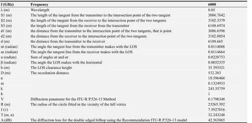
Table 2. The diffraction loss and associated parameters for the double edged hilltop using the Recommendation ITU-R P.526-13 model.
f (GHz) Frequency 6000
λ (m) Wavelength 0.05
S1 (m) The length of the tangent from the transmitter to the intersection point of the two tangent 3086.7642
S2 (m) the length of the tangent from the receiver to the intersection point of the two tangents 3102.3379
S3 (m) the length of the tangent from the receiver from the transmitter 6188.6974
d1 (m) the distance from the transmitter to the intersection point of the two tangents, that is point 3086.6596
d2 (m) the distance from the receiver to the intersection point of the two tangents 3102.0054
d (m) the distance from the transmitter to the receiver 6188.665
αt (radian) The angle the tangent line from the transmitter makes with the LOS 0.0114088
αr (radian) The angle the tangent line from the receiver makes with the LOS 0.0114664
α (radian) Sum of angles αt and αr 0.0228753
β (radian) The angle the LOS makes with the horizontal 0.0032335
h (m) The LOS clearance height 35.393521
D (m) The occultation distance 532.203
n 19.596466
m 0.1324933
k 243.35759
b 1
V Diffraction parameter for the ITU-R P.526-13 Method 0.1798348
R (m) The radius of the circle fitted in the vicinity of the hill vertex 23265.392
J (v) 7.5927016
T (m, n) 32.243248
A (dB) The diffraction loss for the double edged hilltop using the Recommendation ITU-R P.526-13 model 42.563065
Table 2 shows diffraction loss and associated parameters for the double edged hilltop using the Recommendation ITU-R P.526-13 model. From Table 2, the path length (d) is 6188.665 m. Also, the tangent from the transmitter and the tangent from the receiver intersected at a distance of 3086.6596m from the transmitter and a distance of 3102.0054 m from the receiver. The line of sight makes an angle of 0.0032335 radians with the horizontal. The LOS clearance height is 35.393521m. The occultation distance is 532.203m. The diffraction loss computed for the double edged hilltop using the Recommendation ITU-R P.526-13
model is 42.563065 dB.
4. Conclusions
References
[1] Mahafza, B. R. (2016). Radar signal analysis and processing using MATLAB. CRC Press.
[2] Bai, T., & Heath, R. W. (2015). Coverage and rate analysis for millimeter-wave cellular networks. IEEE Transactions on Wireless Communications, 14 (2), 1100-1114.
[3] Pyattaev, A., Johnsson, K., Andreev, S., & Koucheryavy, Y. (2015). Communication challenges in high-density deployments of wearable wireless devices. IEEE Wireless Communications, 22 (1), 12-18.
[4] Sachdeva, N., & Sharma, D. (2012). Diversity: A fading reduction technique. International Journal of Advanced Research in Computer Science and Software Engineering, ISSN.
[5] Patwari, N. ECE 5325/6325: Wireless Communication Systems Lecture Notes, Spring 2010.
[6] Gunnarsson, F., Amirijoo, M., & Moe, J. (2016). U. S. Patent No. 9,264,919. Washington, DC: U. S. Patent and Trademark Office.
[7] Pradhan, C., & Murthy, G. R. (2015). Analysis of Path Loss mitigation through Dynamic Spectrum Access: Software Defined Radio. arXiv preprint arXiv: 1510.04772.
[8] Sai Sanath Kumar, K., Reddy, K. N. K., Pushpavathy, V., Reddy, P. R., Sharma, D., Sharma, P. K., & Krishna, B. V. (2016). Calculation of Path Losses at CM3 for Wireless Body Area Networks (WBAN) by using Different Types of Antennas. International Journal of Applied Engineering Research, 11 (7), 5210-5217.
[9] Agrawal, S., Gupta, N., & Shrivastava, M. (2016). Impact of GSM Spectrum Auction in 900 & 1800 MHz Band. International Transactions on Electronics and Communication Engineering, 1 (1), 18-27.
[10] Malila, B., Falowo, O., & Ventura, N. (2015, September). Millimeter wave small cell backhaul: An analysis of diffraction loss in NLOS links in urban canyons. In AFRICON, 2015 (pp. 1-5). IEEE.
[11] Saman, M. A., Ismail, A. F., Badron, K., Ramli, H. A. M.,
Hashim, W., & Fakrullah, A. N. A. (2015). Development of Spectrum Management Tool for Malaysia Using Open-Source GIS Software. In Theory and Applications of Applied Electromagnetics (pp. 127-135). Springer International Publishing.
[12] Vargas, T. A. A., Peña, J. E. A., Medina, J. G. B., Pulido, J. D. Z., & Peñaloza, M. L. S. (2015, October). Configuration of propagation models for computational simulation of different telecommunications services. In Engineering Applications-International Congress on Engineering (WEA), 2015 Workshop on (pp. 1-6). IEEE.
[13] Jude, O. O., Jimoh, A. J., & Eunice, A. B. (2016). Software for Fresnel-Kirchoff Single Knife-Edge Diffraction Loss Model. Mathematical and Software Engineering, 2 (2), 76-84. [14] Adebayo, T. L., & Edeko, F. O. (2007). Investigation and
Modeling of Diffraction Loss at 1.8 GHZ in a Mountainous Terrain: A Case Study of Olumo Rock, Abeokuta, Nigeria. Research Journal of Applied Sciences, 2 (1), 60-64.
[15] Baldassaro, P. M. (2001). RF and GIS: Field Strength Prediction for Frequencies between 900 MHz and 28 GHz. [16] Parsons, J. D., & Parsons, P. J. D. (2000). The mobile radio
propagation channel. Second edition. John Wiley & Sons. [17] Hacking, K. U. H. F. (1968). Propagation over rounded hills.
BBC Research Department. Research Report No. RA-21, 30. [18] Rice, P. L., Longley, A. G., Norton, K. A., & Barsis, A. P.
(1967). Transmission Loss Predictions For Tropospheric Communication Circuits, Volume 1. Institute For Telecommunication Sciences And Aeronomy Boulder Co [19] Wait JR Conda AM (1959) Diffraction of electromagnetic
waves by smooth obstacles for grazing angles. Journal of Research of the N. B. S. vol 63D
[20] ITU-R P.526-13 (11/2013) Propagation by Diffraction.
Available online at:
http://www.itu.int/rec/RREC-P.526-13-201311-I
[21] Barué, G. (2008). Microwave engineering: land & space radiocommunications (Vol. 9). John Wiley & Sons.