Fault Tolerance in a Multi-Layered DRE System:
A Case Study
Paul Rubel, Joseph Loyall, Richard E. Schantz, Matthew Gillen BBN Technologies, Cambridge, MA, USA
Email: {prubel,jloyall,schantz,mgillen}@bbn.com
Abstract— Dynamic resource management is a crucial part of the infrastructure for emerging distributed real-time embedded systems, responsible for keeping mission-critical applications operating and allocating the resources necessary for them to meet their requirements. Because of this, the resource manager must be fault-tolerant, with nearly continuous operation. This paper describes our efforts to develop a fault-tolerant multi-layer dynamic resource management capability and the challenges we encountered, some due to the fault tolerance requirements we needed to meet and others due to characteristics of the resource management software. The challenges include the need for extremely rapid recovery; supporting the characteristics of component middleware, including peer-to-peer communication and multi-tiered calling semantics; supporting multiple languages; and the co-existence of replicated and non-replicated elements. Making our multi-layer dynamic resource manager fault-tolerant required simultaneously overcoming all of these challenges, presenting a significant fault tolerance research challenge.
Index Terms—fault tolerance, multi-layer dynamic resource management, component middleware, distributed real-time embedded systems
I. INTRODUCTION
Fault tolerance is an important characteristic of many systems, especially mission critical systems that are prevalent in medical, industrial, military, and telecommunications domains. Many of these are distributed real-time and embedded (DRE) systems, combining the challenges of networked systems (e.g., distribution, dynamic environments, and nondeterminism) with the challenges of embedded systems (e.g., constrained resources and real-time requirements). For these systems, failure of critical elements can lead to catastrophic consequences.
One of the most critical elements of large DRE systems is the dynamic resource management capability. As part of the DARPA ARMS program, and in
conjunction with a team of researchers from several organizations, we have been developing a Multi-Layer dynamic Resource Management (MLRM) capability for the total ship computing environment [1]. This MLRM system controls the allocation of computing and communication resources to applications (some critical and others non-critical) and reallocation of resources when failures occur and when missions change, while maximizing operational capability.
MLRM is a critical piece of common infrastructure because it enables the deployment of mission-critical applications and enables them to continue functioning after failures by redeploying them. In order to maintain operation of the applications, the MLRM must itself be able to survive failures. However, MLRM has some characteristics, typical of similar DRE systems, that present challenges to making it fault-tolerant. In this paper, we describe our efforts to make the MLRM fault-tolerant, concentrating on the following characteristics and challenges:
• Rapid recovery – Because MLRM functionality is critical to keeping applications running and supporting ongoing missions, it is important that it be available continuously. Therefore, if MLRM fails it must recover as rapidly as possible, aiming for near zero recovery time.
• Component middleware – MLRM and the applications it deploys are developed using emerging component middleware that offers many advantages, but exhibits deployment and architectural characteristics that differ from the object-based middleware most existing fault-tolerant software supports.
• Peer-to-peer communication – Much established fault tolerance software supports only pure client-server semantics, i.e., clients calling replicated servers. In component software, and in the MLRM software, components can simultaneously be clients and servers. • Multi-tiered semantics – Traditional fault tolerance
concentrates on a single tier, in which a call from a non-replicated client to a replicated server returns without spawning additional calls to additional servers. MLRM exhibits multi-tiered semantics, in which a call to a server frequently calls additional servers, and clients and multiple tiers of servers can be replicated. This work was supported by the Defense Advanced Research
Projects Agency (DARPA) under contract NBCHC030119. Approved for Public Release, Distribution Unlimited
This complicates fault tolerance because of the need to manage consistency and replication across multiple component boundaries.
• Multiple languages – MLRM contains both C++ and Java elements and multiple ORBs. Most existing fault-tolerant solutions support one or the other.
• Large numbers of elements with various degrees of fault tolerance needs – The MLRM and the total ship computing environment in which it operates are large distributed systems, with many interoperating elements, not all of which need to be fault-tolerant to the same degree. Traditional fault tolerance solutions that require all elements to be part of a single approach fault tolerance infrastructure are unsuitable.
This paper describes how we overcame these challenges to create a rapidly recovering fault-tolerant MLRM. First, we describe the MLRM architecture and its characteristics. Then we address each of the challenges in more detail and describe the solutions we developed to overcome them. We then evaluate the fault tolerance exhibited in the MLRM and the speed with which it recovers. We then discuss related work and present conclusions.
II.
III. FITTING FAULT TOLERANCE INTO A MULTI
-LAYERED DRESTRUCTURE
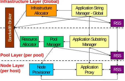
The MLRM architecture, illustrated in Fig. 1, has the following layers:
• The Infrastructure Layer deploys missions (consisting of sets of interacting applications known as application strings), assigns them to resource pools and security domains, and determines their relative priorities. This layer works to ensure that high-level mission objectives can be met while delegating particular decisions to lower layers. It can choose to deploy or redeploy application strings as failures occur or mission needs change and is also responsible for deciding which application strings should be run when sufficient resources are not available to meet all needs. • The Pool and Application String Layer coordinates groups of related computing nodes (pools) and related applications grouped into application strings. It
receives deployment commands from the infrastructure layer and is responsible for choosing the hosts on which individual applications will run, taking into account such factors as resource utilization, collocation benefits, interdependencies between applications in a string, as well as other needs. It also coordinates the shutting down of applications within its pool. The Pool and Application String Layer also aggregates status reports from pool level resources and reports events to the infrastructure layer.
• The Node layer controls access to individual computing and communication resources. It is responsible for managing applications on a single host and for reporting status to the Pool and Application String Layer elements.
The pool structure uses diversity in location and clustering to protect against large-scale damage or major system failures affecting a large portion of computing resources. With pools of computing hardware spread in different locations, the failure of one pool of resources still leaves sufficient computing capability for critical operations.
Whereas the pool and node layers rely on redundancy and redeployment to deal with failures, the infrastructure layer cannot, since the infrastructure layer applications must themselves be deployed on hosts in pools and the loss of a single host or pool cannot be allowed to take the MLRM down with it. This paper concentrates on making the Infrastructure Layer MLRM elements fault-tolerant. In order to ensure that the MLRM remains available, we use replication to spread its functionality over multiple hosts and pools. This ensures that even after catastrophic pool failures the MLRM is available to carry out its job of deploying or redeploying applications and application strings to the remaining hosts and pools. When a pool fails, the infrastructure MLRM elements of the surviving pools take over and initiate the actions necessary to deploy critical functionality across the remaining pools. In this case, there is no need to replicate the pool or node level MLRM elements, since they will still exist in the surviving pools.
CHALLENGES AND SOLUTIONS IN MAKING THE
MLRM FAULT-TOLERANT
Making the MLRM fault-tolerant presented a number of challenges. Some of these were challenges in quantity, such as providing rapid responses to failures or efficiently supporting a large number of applications. Others were challenges of quality, where we needed a specific type of solution due to the way in which the MLRM was developed or deployed. Supporting component middleware, multiple implementation languages, peer-to-peer interactions, and multi-tiered communication semantics on account of the existing MLRM infrastructure exemplify this type of challenge.
Application Substring Manager Pool
Manager Resource
Allocator
RSS Infrastructure
Allocator
Application String Manager - Global
RSS
As shown in Fig. 1, the Infrastructure Layer of the MLRM is not a monolithic whole but rather consists of four interacting management applications: the Infrastructure Allocator and Application String Manager-Infrastructure Layer (Global)
Pool Layer (per pool) Node Layer
(per host) ProvisionerNode Application Proxy RSS
Band
w
idth Br
ok
er
Global (collectively known as the IA/ASM-G due to the fact that both components are collocated within a single process); the Resource Status Service (RSS), which monitors and disseminates information about the state of the system; and the Bandwidth Broker (BB), which ensures bandwidth is allocated appropriately. Each of these management applications has different characteristics, which contributed to the design of our fault-tolerant MLRM.
A. Rapid Recovery from Failures
Since the MLRM has responsibility for recovering application functionality in the face of a node or pool failure and the application functionality cannot be recovered until the MLRM has recovered, the infrastructure layer MLRM functionality must be constantly available. Therefore, the primary requirement for our MLRM fault tolerance is speed of recovery. Because of the very short recovery requirements, and since our fault model is concerned with node loss rather than misbehavior, we employ a tolerance strategy that actively replicates [2] elements when possible and passively replicates [3] only when necessary (i.e., when the application semantics are inappropriate for active replication). This tolerance strategy allows us to recover quickly while maintaining flexibility.
In an active scheme, each replica processes incoming messages and sends out responses. Ideally, the failure of a replica should not affect existing replicas, which will keep on receiving and replying to messages, and recovery from a failure should be instantaneous. As long as at least one replica out of n has not failed, any remaining replica will be able to carry on and n-1 simultaneous failures can be tolerated.
To ensure that the responses of one replica are indistinguishable from another one taking its place, active replication requires that replicas are deterministic in their processing of messages. That is, the same input messages must result in the same output messages at each replica. Of the MLRM elements, only the IA/ASM-G is deterministic and suitable for active replication. For the other elements, we had to make a determination whether to try to make the RSS and BB deterministic or to use an alternative replication scheme for them.
We concluded that a warm passive replication scheme was the best alternative for providing fast recovery for the BB and RSS. Making them deterministic would materially change their behavior in unacceptable ways and would have been a substantial engineering effort.
In a warm passive approach, many replicas are running but only one of them, the leader, is processing messages and sending replies. When the leader finishes processing and before it sends its response, the leader sends its state to the other replicas. This allows the other replicas to take over in case of a leader failure and have the same state as the leader when it sent its latest message. The non-leader replicas integrate the leader’s state when they see the reply sent by the leader. At this point they are ready to take over for the leader in the case of a failure. Passive replication, like active, can survive n-1 failures with n replicas.
Passive replication is not as fast as active, due to the overhead of gathering state in addition to message processing, but in some cases it is the best available alternative as it is applicable to more types of applications. Its resource utilization can also be less than active if the processing of messages is more expensive than the gathering of state at the leader and setting of state at the non-leader(s).
The BB provided an additional challenge for replication as it made use of a commercial open-source database, MySQL, as illustrated in Fig. 2. The BB functionality was split between a stateless front-end and a MySQL DB that stored information on the back-end. In order to not have a single point of failure both of these elements needed to be made fault-tolerant. We replicated the front-end using a warm passive scheme that was optimized for interactions with a DB. This extra optimization was necessary because the MySQL DB was not a CORBA application, unlike the rest of the MLRM, and could not make use of our middleware to guarantee message delivery. Instead of relying on guaranteed delivery, we used DB guarantees to ensure that actions were only taken once. Our solution replicated the DB using an off-the-shelf clustering solution modified to detect and recover quickly from failures. By carefully configuring the DB tuning parameters and making a small source code change to allow DB identifiers to be specified at configuration-time rather than coordinated at the time of a failure (saving time and reducing timing variance), we were able to quickly recovery from DB failures.
Our replication schemes: active, for use with the IA/ASM-G; warm passive, for use with the RSS; and an optimized warm passive, for use with the BB, were implemented using the Spread [4] group communication system for sending messages and the MEAD [5] fault tolerance framework for interception of application messages to be sent using Spread, suppression of duplicate messages, and reconstituting replicas. Both of these were customized, and in the case of MEAD, extended and enhanced, for use with the MLRM.
Spread is a group communication system that utilizes a per-host daemon and a library that gets linked with each application that needs to communicate with the local
Infrastructure Allocator (IA)
Application String Manager (ASM)
Resource Status Service (RSS) Bandwidth
Broker (BB)
BB Database
MLRM Management
MLRM Management
MLRM Management and BB Database
MLRM Management and BB Database
Actively Actively Replicated Replicated
Passively Passively Replicated Replicated
Replicated Replicated using using MySQLMySQL clustering clustering
Figure 2. We replicated the Infrastructure Layer MLRM functionality using a combination of techniques (active, passive, MySQL clustering)
daemon. The Spread daemon coordinates the sending and receiving of messages between group members, in such a way as to provide messaging characteristics necessary for replication, such as total-ordering and reliable delivery.
The Spread daemon also detects node failures and issues group membership changes for each group that has a member on the failed node. However, the default configuration that Spread has “out of the box” can take over 5 seconds to detect node failures. We needed faster reaction time from the Spread daemon. Based on previous work that documented Spread tuning [6], we adjusted the timeout parameters in Spread to obtain failure detection times under 200 milliseconds. These included increasing the frequency of failure detection messages and decreasing the quiescent time required between the loss of a member and the declaration of a new group membership.
While these tuned timeouts made the node-failure detection time faster, they also made the Spread daemon more susceptible to false-positives caused by latency related to processor scheduling at the operating system level. Our initial testing showed that a high CPU load on a node would cause the Spread daemon to get scheduled less often than required, which in turn caused the other nodes to report the high-load node as failed. The daemon needed to run frequently for very small amounts of time. We solved this problem by making the Spread daemon the highest priority process on every node. Given the default scheduling time-slice on Linux (1 ms), this was sufficient to guarantee that the Spread daemon got a chance to run as often as it needed to.
The changes made to MEAD were not done to increase the speed of recovery but rather to support qualities of MLRM that MEAD did not previously support. These included supporting component middleware, multi-tiered semantics, and multiple application development languages, discussed in the next sections.
B. Integrating Fault tolerance with the CORBA Component Model
Many fault tolerance concepts, and existing code bases (including MEAD), were designed to work with replicated servers in client-server architectures, such as CORBA 2 [7]. MLRM has been developed using the CORBA Component Model (CCM, or CORBA 3 [8]), which has many advantages including lifecycle support and availability of design tools. However, there were three main challenges associated with providing fault tolerance in a CCM environment that needed to be overcome in order to make the MLRM fault-tolerant.
The first challenge was that the MLRM, and CCM in general, exhibits a peer-to-peer structure, where components can play the role of both client and server simultaneously. While such behavior was possible in CORBA 2, it was not nearly as common and a solution that did not support it was often still acceptable. The initial MEAD software base only supported replicated servers with duplicate suppression of responses from replicated servers back to non-replicated clients. We extended this code base to support the replication of both
clients and servers, and by monitoring and controlling the CORBA message request identifiers, we were able to provide the suppression of duplicate requests (from replicated clients) and responses (from replicated servers). This allowed the MLRM to continue to function as it was designed.
The second challenge was that the MLRM has multi-tiered interactions. In these interactions, a client may make a call on a server, which in turn makes a call on another server, any and all of which can be replicated. These interactions can, if not handled properly lead to non-determinism or deadlock in active replicas and loss of synchronization in passive replicas. We dealt with this problem through a combination of techniques. We extended the active replication scheme to support callbacks in a single-threaded manner to prevent deadlock while preserving determinism.
The passive scheme proved more challenging and was less amenable to a single solution for multi-tiered interactions. The most straightforward solution from a middleware provider point of view is to gather the state whenever a request or reply is delivered to the replica. While this is easier for the middleware provider, it can be more difficult for the application developer due to complexities in gathering state. Getting the state after a reply is relatively straightforward as it is just another sequential call on the replica. Getting state after a request is more difficult as it entails a nested call and the state needs to reflect that a call is in progress.
Another solution is to allow the application to notify the middleware when the state changes. This requires the application developer to be involved in the fault tolerance, but may be preferable to forcing them to develop a set of complex get and set state routines. This application-driven state transfer approach is particularly useful if the replicas communicate using one-way messages or change their state when they are not sending or receiving messages, for example by making use of timers.
Due to the fact that the RSS made use of timers and one-way messages and that we felt comfortable making fault tolerance changes in the application logic, we chose to manually trigger state transfer for the passively replicated RSS at appropriate times.
The third challenge was that the deployment architecture of CCM is more complicated than most CORBA 2 solutions. Before a component can be deployed using CIAO [9], an open-source C++ CCM implementation, a Node Daemon (ND) starts up a Node Application (NA), which acts as a container for new components, as illustrated in Fig. 3. The ND makes CORBA calls on the NA, instructing it to start
Host
Execution
Manager DaemonNode
Process (replicated)
Component Node
Application Load
Component Node
Application Load Deploy
Deploy
components, which are not present at NA start up time. Note that the components, when instantiated in the NA, need to be replicated, but the NDs should not be.
To illustrate this point, consider an existing fault-tolerant component when a new replica is started. Since MEAD ensures that all messages to and from one replica are seen at every replica, the existing replicas will receive an extra set of bootstrap interactions each time a new replica is started. This will not only confuse the existing replicas, but the responses from the new replica will also confuse the existing NDs. In order to stop this confusion and allow replicas to be deployed, we developed a way to allow direct point-to-point interactions during the bootstrapping process and then switch to using reliable, ordered, group communications once the replicas are started. This is further discussed in subsection D.
The CCM envisions components interacting within a large-scale assembly. Architecturally, the current MLRM is made up of multiple assemblies. This decision was a pragmatic one since the ability to dynamically redeploy applications within an assembly was not supported at the time by CIAO. This meant that we could not add new replicas to the system during execution time, but only at startup time if we used a large-scale assembly. Using multiple assemblies allows us to set our unit of fault tolerance, the process, to the unit of CCM deployment, simplifying the task of making the MLRM fault tolerance. We chose processes as our unit of fault tolerance since it is easier to control and order input and output into a process than other smaller or larger application units.
C. Supporting a Multi-Paradigm, Multi-Language Environment
The MLRM environment is not a simple homogeneous one. It contains C++ components intermixed with Java and C++ CORBA objects as well as different ORBs, aspects of which need to be made fault-tolerant and interoperable. This heterogeneity requires a fault tolerance solution that can support components and objects programmed in both Java and C++. Initially MEAD only supported C++ and TAO [10]. It did not support Java, due to difficulties stemming from non-determinism such as garbage collection and threading. In order to be able to run the MLRM we enhanced MEAD so that it worked with the two ORBs used by the MLRM: JacORB [11], a Java ORB, and CIAO, TAO’s CCM implementation. In adding support for JacORB into MEAD we did not remove all sources of non-determinism from Java, but rather dealt with the threading of network IO in such a way that JacORB behaved deterministically when used with active replication and could be used with passive replication.
Whereas C++ applications developed with TAO use non-blocking mechanisms, such as the select system call, to wait for responses, the JVM often makes a new thread for each operation and blocks, waiting for the operation to finish. This call style is quite different from what MEAD initially supported and in order to deal with it we added code to the read and write calls that effectively blocked the application while registering a callback.
When data was available the waiting thread would be called back and allowed to progress. This preserved the semantics expected by the JVM while allowing us to deliver messages in the ordered manner necessary to make our fault tolerance solution work, all without application knowledge.
Interactions between CORBA components and objects, whether using TAO, CIAO, or JacORB, went quite smoothly compared to the differences encountered supporting Java and C++. Due to the standardization provided by CORBA and a common use of Spread these interactions were not problematic.
D. Limiting the Effects of the Fault Tolerance Infrastructure
In order to keep replicas consistent, our fault tolerance code uses the Spread group communication system (GCS) to ensure that messages are reliably delivered to each replica in the same consistent order. Without these guarantees, replica state could diverge and the replicas would no longer duplicate one another. Imagine active replicas that take in arithmetic operations to perform on their present value. With an initial value of 5 receiving ‘add 2’ and then ‘multiply by 10’ leads to quite a different value than receiving ‘multiply by 10’ and then ‘add 2’. At this point the instances are no longer replicas. Similar problems with consistency can occur for passive replicas if a failure occurs as a response is being delivered. To prevent this from happening, any interactions with a replica, after the initial CCM bootstrapping, must pass through Spread. Previously, in the context of small example systems, it was acceptable to force the entire system to sit atop this GCS infrastructure and many research-grade fault tolerance solutions did so, including MEAD. The overhead was a secondary concern to being able to provide fault tolerance.
This assumption does not hold in the MLRM case, where we not only need to replicate the Infrastructure Layer but must also conserve resources for the use of the Node Layer, where the important work, from the user’s point of view, is accomplished.
It would be prudent to limit the use of Spread/MEAD solely to the Infrastructure Layer. Unfortunately, due to consistency concerns, illustrated above, elements in the Pool Layer must interact with the Infrastructure Layer using Spread/MEAD. However, since the Pool and Node Layers are not replicated, they do not need the same consistency guarantees when interacting among one another. Furthermore, from a usability and performance perspective, we do not want to force the Spread/MEAD infrastructure on the Node Layer, which can include hundreds of components with real-time constraints doing the actual work of the system. Even a small unnecessary processing, memory, or network overhead at the Node Layer would limit the amount of work that could be done by the nodes.
In our approach to fault tolerance, Spread/MEAD is strictly necessary for the replicas, all of which are contained in the MLRM’s Infrastructure Layer, and each replica is required to use Spread/MEAD for all its communications. However, every entity that does not interact with a replicated entity, for example, the contents of the Node Layer, does not need to use Spread/MEAD. For those components that interact with both replicated and non-replicated entities, as happens in the Pool Layer, we developed new functionality to ensure that they respond to a request in the same manner they received the request. If a request is received over TCP it is responded to over TCP and similarly for Spread. When initiating a request, MEAD compares the destination IP and port combination against a list of combinations for which Spread should be used. If the destination port is on this list the message will go out over Spread, otherwise it will use TCP as if MEAD were not present. This effectively limits Spread/MEAD to only the areas where it is strictly required, freeing resources for other uses and simplifying major parts of the rest of the system.
This same mechanism is used to deploy new replicas. Until a replica has been started the ND and NA interact without group communication as neither is replicated. Once the replicated component starts, no more ND/NA interactions are necessary and the replicas use only Spread. Currently the list of IP address and port combinations that will use Spread rather than TCP must be known at system start time. A planned improvement to the MEAD software includes removing this requirement in favor of auto-configuration.
Note that this technique improves over previous approaches to this challenge. Previously, the solutions were to either force everything in the system to use the GCS, which is unreasonable in large, highly dynamic systems; or to insert special gateway elements [12], which have to be made fault tolerant themselves and add overhead. In contrast, our technique simply introduces an additional role for already existing elements, those at the edge of a GCS group, that enables them to communicate with replicated and non-replicated elements.
Fig. 4 illustrates this scheme and shows two replicated components, in the Spread clouds, interacting with three transition components, which in turn interact with four components that are unaware of the underlying Spread infrastructure.
IV. EXPERIMENTAL VALIDATION
In order to support our claims about the fault tolerance
attributes of the MLRM, we ran a number of experiments. Our initial experiments measured the time to recover from a failure under two failure scenarios, a single pool failure, and two cascading pool failures. We also gathered experimental data on the time needed to deploy and integrate a new replica into an existing group of replicas, which is necessary to maintain a certain level of fault tolerance over time in the presence of faults.
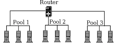
A. Experiment Setup
Fig. 5 depicts a network setup used to test our claim of providing rapid recovery from failure. Our experiments were carried out using 2.8GHz Xeon PCs running Linux and using 100Mbit Ethernet. The hosts were split into three pools of three hosts each and were connected using a multi-homed Linux router.
We ran two types of experiments to measure recovery speed. In both cases we measured the time required for our fault tolerance MLRM applications to detect and recover from failures. In this case recovery meant that the MLRM was able to redeploy applications. We did not measure the time to complete the redeployment but rather measured the time from failure until it would be possible to start redeployment, due to the MLRM having recovered and being stable. We did, however, check that the redeployment succeeded to ensure our recovery had been successful.
For our first scenario, A, we used two pools of three hosts and measured the effects of a single pool failure. In this scenario a whole pool is lost (from the perspective of the mission-critical software's user) instantaneously, as would happen during a major power failure or if the hosting facility was destroyed. In the second scenario, B, we used three pools and crafted the scenario to showcase the robustness of our fault tolerance solution. For this experiment we failed one pool and before the failover was complete introduced a failure in one of the remaining two pools. In order to ensure that we had two cascading failures rather than two sequential failures, or two simultaneous failures, we post-processed our runs and reported on only those where the failures were cascading. When introducing the cascading failure we waited 10 ms, an experimentally derived value that gave us a good probability of having a cascading failure, between pool failures.
In both scenarios we simulated failure by creating a network partition so that packets sent to or from hosts in the failed cluster would be dropped at the router. This partitioning accurately simulates the instantaneous failure of the pool while also allowing us to note the exact time the failure occurred (as opposed to trying to obtain a timestamp for physically pulling a plug). We did not
Spread and TCP
Spread Cloud
TCP
Spread
Figure 4. Our fault tolerance solution enables the coexistence of group communication (Spread) and non-group communication, where elements at the edge of the interaction communicate via both
simulate a failure by killing processes, which would allow the operating system to close sockets. If we had allowed the OS to close the sockets the failure detection time would have been much faster, due to the OS sending notification of the closed socket, but would not have accurately simulated the complete loss of the pool. We chose catastrophic pool failure in an attempt to simulate the most severe failure for our purposes.
To run the experiments in a realistic configuration, we started the MLRM infrastructure on the pools in use and deployed 10 application strings with 15 applications per string using the MLRM. The application strings were deployed on the first pool to fail. This ensured that the pool failure would tax the system to the maximum extent, as each string would need to be redeployed at least once, and perhaps twice in the B scenario.
B. Experiment Results for Failure Recovery
For each experiment, A and B, we made five runs. On each of these runs we measured the time of the initial failure injection, the time that each MLRM element noted the failure (except for the BB DB, which, due to its COTS nature, was not instrumented to note failure detection time) and the time at which each MLRM element recovered from the failure. For the BB we measured both the time for the BB front-end to recover as well as the back-end BB DB to successfully reply to a simple query. We split the BB measurements due to the large difference in recovery strategies, the front-end using
our fault tolerance infrastructure and the back-end using MySQL clustering.
Table I, Table II, Fig. 6, and Fig. 7 show recovery times for the A and B scenarios. In the tables we show values for both the time taken from fault injection until recovery and from fault detection to recovery. The figures report the times from injection until recovery. The time of fault detection is the earliest time that any replica detects that a fault has occurred (using Spread’s group membership consensus protocol). In either case recovery is complete when the last replica has completed its recovery. Note that due to the distributed nature of the failure detection some applications may receive notification before others and in some cases this may allow recovery to proceed in parallel with detection if one application is recovering while another is still trying to detect the failure. In the data presented here this occurred in run 1 in Fig. 7. The IA/ASM-G, which usually detects the fault first, and is also the fastest to recover from a failure due to being actively replicated, detected the failure after the RSS and BB, which were recovering while the IA/ASM-G was still waiting for notification of the failure. This manifests itself in quicker MLRM recovery.
As noted in Table I, the recovery of the MLRM is complete after a single failure in less than 150 ms from fault injection and less than 20 ms from detection. For the B scenario, shown in Table II, recovery from two cascading failures is complete in less than 330 ms from
TABLE I.
RECOVERY TIME FOR SCENARIO A
Failure to Recovery (FtR) Detection to Recovery (DtR)
Management Only(ms)
Management and BB DB(ms)
FtR - Average 128 142
FtR - Minimum 118 134
FtR - Maximum 136 162
FtR - Standard Deviation 7.0 10.5
DtR - Average 17.2 31.9
DtR - Minimum 16.8 17.5
DtR - Maximum 17.5 60.6
DtR – Standard Deviation 0.3 16.7
TABLE II.
RECOVERY TIME FOR SCENARIO B
Failure to Recovery (FtR) Detection to Recovery (DtR)
Figure 6. Time to recover after a single pool failure
Management Only (ms)
Management and BB DB(ms)
FtR - Average 265 306
FtR - Minimum 260 272
FtR - Maximum 272 329
FtR - Standard Deviation 4.2 19.1
DtR - Average 18.9 59.4
DtR - Minimum 18.4 22.9
DtR - Maximum 19.5 84.1
DtR - Standard Deviation 0.4 20.2
the introduction of the failures and in less than 70 ms from the time of detecting the faults. While providing constant availability of the MLRM is a relative term we feel that we have achieved it in the context of the MLRM in these experiments.
C. Results for Starting a New Replica
While failover time is important in the short-term to continue after a failure, over the long-term being able to reintegrate or reconstitute a new replica into the system is also important so that periodic failures do not eventually lead to complete system failure.
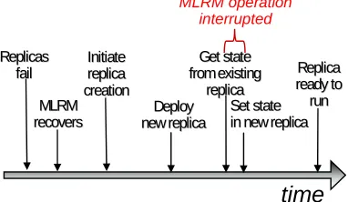
Deployment of a new MLRM application replica takes just a few seconds. During all but a tiny part of that time, the MLRM functionality (i.e., the surviving MLRM replicas) is up and running and fully functional. There is a brief interruption (on the order of a few 10s of milliseconds) when the MLRM synchronizes its state with the new replicas and is unavailable to handle new requests for service. The interruption is necessitated by the fact that the state must be consistent while it is being gathered and for this to happen, replica processing must stop while the state is gathered. The timeline shown in Fig. 8 shows the replica reconstitution process and the brief interruption of MLRM functionality as state from an existing replica is transferred to the new replica.
As shown in Fig. 9, the time to start up a new replica is application dependent. A large application will take longer to load into the system and complicated applications may take longer to prepare to execute. For the IA/ASM element, the time to deploy a new replica component consists mainly of the time to deploy new CIAO components. With the BB and RSS, it is the time associated with starting new Java processes, including starting the JVM, loading classes, and so on. All of this is independent of the fault tolerance infrastructure over which they are running. As shown in Fig. 9, any of the three MLRM replicas are fully integrated into the system after approximately 2.1 seconds in the worst case.
While the absolute time for starting up a new replica is important in order to maintain the continuous uptime of the system we want to minimize the downtime to the replicas where no work can be done due to state synchronization with the new replica. Fig. 10 shows the downtime measured at the three MLRM applications due to state gathering. Note that this is also important in the failure-free case for passive replicas, as the leader of a group of passive replicas will gather its state with each
message. This state gathering time is relative to the complexity of the state being gathered. In the case of the BB, which has no application state, the gathering is done almost immediately. The IA/ASM-G state is gathered in approximately 25 ms while the RSS, the application with the most complex state takes approximately 55 ms to gather its state.
Figure 9. Time to start a new replica
Figure 10. MLRM downtime during replica restart
V. Related Work
Fault tolerance for distributed systems is an active area of research and many projects have made significant contributions. Early replicated object work was done in the ISIS [13] system. This was followed by systems like the CORBA service oriented OpenDreams [14] and the interception based Eternal [15], and AQuA [16], all of which supported replicated server objects using CORBA.
The Fault Tolerant CORBA standard [8] specifies reliability support through the replication of CORBA servers, and the subsequent distribution of the replicas across the nodes in the system. The FT CORBA specification has not kept up with the change in CORBA 3 and so does not support the CORBA component model and is in fact in the process of being superceded by a real-time/fault-tolerant specification currently in the request for proposal phase.
Another, more recent, solution for providing fault tolerance for CCM applications is found in CARDAMOM [17]. The CARDAMOM system provides partial CCM support on top of TAO and JacORB and implements portions of the FT CORBA specification to provide warm-passive replication.
The AspectIX [18] project also provides fault tolerance for non-CCM CORBA applications using Java and JacORB through middleware, which provide communication as well as deterministic threading for Java applications. Calls to the middleware are inserted MLRM operation
interrupted
time
Get stateGet state from existing from existing
replica replica Replicas
Replicas fail
fail Replica Replica
ready to ready to
run run Initiate
Initiate replica replica creation creation
Deploy Deploy new replica new replica MLRM
MLRM recovers
recovers Set stateSet statein new replicain new replica
using source transformation tools that insert calls into the application source code.
Work has also been done to provide support for multi-tiered replication. Kemme [19] presents a solution for a passively replicated middle-tier interacting with a non-replicated client and non-replicated DB back-end. Kistijantoro [20] presents additional work integrating independent replication solutions for multi-tiered transactional systems.
VI.CONCLUSIONS
Providing fault tolerance in DRE systems involves carefully crafting and integrating techniques to not only meet reliability requirements, but also to match the characteristics of the systems. The work that we report in this paper not only provides a practical case study of inserting fault tolerance into a complex system of interacting components, but also provides several significant results in fault tolerance for DRE systems. First, it improves the design and implementation of several fault tolerance constituent elements, making them applicable to larger classes of systems and problems. These improvements include the following:
• The coexistence of GCS and non-GCS, making GCS systems more suitable for large DRE systems with a mixture of replicated and non-replicated applications.
• Support for peer-to-peer and multi-tiered semantics, which are more prevalent in DRE systems than the pure client-server, single-tiered replication semantics that were previously supported.
• Replication of component applications written in multiple languages and using multiple ORBs, removing some of the limitations in using fault tolerance solutions in modern software architectures.
While several of these have been investigated before, a second significant result is that providing fault tolerance in DRE systems similar to the MLRM requires all of them. We can conclude that this is the more typical case, since many DRE systems are networked systems of independently developed subsystems (as the MLRM is), with many interoperating elements (some critical, others less so), written in different languages and on different middleware platforms.
A third result of this work is the identification and management of the tradeoffs involved in building fault tolerance for DRE systems. The mission-critical nature of the MLRM system clearly identified a requirement for nearly continuous availability, which in turn motivated the use of active replication to mask faults. However, aspects of some MLRM elements made them inappropriate for using active replication. The techniques that we used to integrate multiple techniques, each matched to the characteristics of specific system elements, resulting in fault tolerance with very rapid
recovery, should be generally useful to developers of large mission-critical DRE systems.
ACKNOWLEDGMENT
We would like to thank our colleagues at CMU for their help with MEAD, particularly Aaron Paulos and Priya Narasimhan. Vanderbilt University’s Distributed Object Computing (DOC) group has been invaluable in helping with CIAO and component deployment. Telcordia and SRC have also made valuable contributions to our work.
REFERENCES
[1] R. Campbell et al, “Toward an approach for specification of QoS and resource information for dynamic resource management,” in Second RTAS Workshop on Model-Driven Embedded Systems (MoDES '04), Toronto, Canada, May 25-28, 2004
[2] F. B. Schneider, “Implementing fault-tolerant services using the state machine approach: a tutorial,” ACM Computing Surveys, 22(4) pp. 299--319, December 1990. [3] N. Budhijara, K. Marzullo, F. Schneider, and S. Toueg,
Distributed Systems, chapter, “The primary-backup approach”, pp 199-216. Addison-Wesley, Wokingham, 2nd edition, 1993.
[4] Y. Amir, C. Danilov, M. Miskin-Amir, J. Schultz, and J. Stanton, “The spread toolkit: architecture and performance,” Johns Hopkins University, Center for Networking and Distributed Systems (CNDS) Technical report CNDS-2004-1
[5] P. Narasimhan et al, “MEAD: support for real-time fault-tolerant CORBA,” in Concurrency and Computation: Practice and Experience, vol. 17, no. 12, 2005, pp. 1527-1545.
[6] R. Kukura and T. Bracewell, “Raytheon company DARPA program composition for embedded systems (PCES) final report”, June 30, 2005.
[7] Object Management Group, The Common Object Request Broker: Architecture and Specification, 2.3 ed., June 1999. [8] Object Management Group, The Common Object Request
Broker: Architecture and Specification, 3.0.3 ed., March 2004.
[9] N. Wang et al. “QoS-enabled middleware”, in Middleware
for Communications, Qusay Mahmoud, Ed. Wiley and
Sons, New York, 2003
[10]D. C. Schmidt, B. Natarajan, C. Gill, N. Wang, and A. Gokhale, “TAO: a pattern-oriented object request broker for distributed real-time and embedded systems,” IEEE Distributed Systems Online, vol. 3, no. 2, Feb. 2002 [11]G. Brose, “JacORB: implementation and design of a java
ORB,” in IFIP WG 6.1 International Working Conference on Distributed Applications and Interoperable Systems – DAIS’97, Cottbus, Germany, Chapman & Hall 1997. [12]P. Narasimhan, L. E. Moser, and P. M. Melliar-Smith.
“Gateways for accessing fault tolerance domains”, in
Proceedings of Middlwware 2000, Lecture Notes in Computer Science 1795, pp. 88-103, April 2000
[13]K. Birman, "The process group approach to reliable computing," CACM, 36, 12, pp. 37-53, December 1993. [14]R. Guerraoui, P. Felber, B. Garbinato and K. Mazouni.
[15]L. E. Moser, P. M. Melliar-Smith and P. Narasimhan, "Consistent object replication in the eternal system", in Theory and Practice of Object Systems, vol. 4, no. 2 (1998).
[16]Y. (J.) Ren et al, “AQuA: an adaptive architecture that provides dependable distributed objects,” in IEEE Transactions on Computers, vol. 52, no. 1, January 2003, pp. 31-50.
[17]A. Corsaro, “CARDAMOM: a next generation mission and safety critical enterprise middleware,” in Third IEEE Workshop on Software Technologies for Future Embedded
and Ubiquitous Systems (SEUS 2005), 16-17 May 2005,
Seattle, WA, USA. IEEE Computer Society 2005
[18]H. P. Reiser, R. Kapitza, J. Domaschka, and F. J. Hauck, “Fault-tolerant replication based on fragmented objects,” in
6th IFIP WG 6.1 International Conference on Distributed Applications and Interoperable Systems - DAIS 2006, (June 14-16, 2006, Bologna, Italy). 2006, pp. 256-271. [19]B. Kemme, M. Patino-Martinez, R. Jimenez-Peris, and J.
Salas, “Exactly-once interaction in a multi-tier architecture,” in VLDB Workshop on Design, Implementation, and Deployment of Database Replication, Trondheim, Norway, August 2005.
[20]A. I. Kistijantoro, G. Morgan, S. K. Shrivastava, and M. C. Little, "Component replication in distributed systems: a case study using enterprise java beans," in 22nd International Symposium on Reliable Distributed Systems (SRDS'03), 2003.
Paul Rubel received B.S. degrees in Computer Science and Computer Engineering from Washington University in St. Louis in 1998 and his M.S. in computer science from the University of Illinois at Urbana-Champaign in 2000. Mr. Rubel is a Staff Scientist in the Distributed Systems Technology group at BBN Technologies. His research focuses on providing fault tolerance and survivability for adaptive distributed systems. He is a member of the IEEE.
Joseph Loyall received his B.S. degree in computer science from Indiana University in 1985 and his M.S. and Ph.D. in computer science from the University of Illinois in 1988 and 1991, respectively. Dr. Loyall is a Division Scientist and one of the leads of the Distributed Systems Technology Group at BBN Technologies. He has been the PI for several research programs in the areas of quality of service, resource management, real-time systems, adaptive middleware, embedded systems, software engineering, and fault tolerance. Dr. Loyall is a senior member of the IEEE and a member of the ACM and the AIAA. He holds three patents and is the author of over 50 publications, including book chapters, journal articles, conference papers, and workshop papers.
Richard E. Schantz received his Ph. D. degree in Computer Science from the State University of New York at Stony Brook, in 1974, and an undergraduate degree in Mathematics from NYU in 1968. Dr. Schantz is a principal scientist at BBN Technologies in Cambridge, Mass., where he has been a key contributor to advanced distributed computing R&D for the past 32 years. His research has been instrumental in defining and evolving the concepts underlying middleware since its
emergence in the early days of the Arpanet and Internet. Most recently, he has led research efforts toward developing and demonstrating the effectiveness of middleware support for adaptively managing realtime end-to-end Quality of Service and system survivability. He is a Fellow of the ACM.
Matthew Gillen received his B.S. degree in computer science from Ohio University in 2000. Mr. Gillen is a Staff Scientist in the Distributed Systems Technology Group at BBN