Abstract— Recent historic events have shown that buildings that are designed in compliance with conventional building codes are not necessarily able to resist blast effects. It was observed in the past events that progressive or disproportionate collapse generally occurred due to deficient blast performance of the structure, albeit in compliance with conventional design codes. In the past, safety of structures against blast effects was ensured, to a limited extent, through perimeter control; which minimizes damage by preventing the direct impact of the blast effects on the building. With the emergence of blast resistant structural design, methodologies to inhibit progressive collapse through the structural components performance can be developed, although there are no available adequate tools to simulate or predict progressive collapse behaviour of concrete buildings with acceptable precision and reliability. This paper presents part of an effort to find an affordable solution to the problem. S tate of the art review of the blast analysis and progressive collapse analysis procedures will be presented. Preliminary analysis has been carried out to establish the vulnerability of a typical multi -storey reinforced concrete framed building in Riyadh when subjected to accidental or terrorist attack blast scenarios. In addition, the results of the blast vulnerability assessment will be used to develop mitigation approach to control or prevent progressive collapse of the building.
Index Term— Progressive Collapse, Blast load, LS -DYNA, Finite element model.
I. INT RODUCT ION
In the recent past, buildings and structures across the globe have become more vulnerable to the threat of terrorism, accidental explosions, the proliferation of weapons and other extreme threats. Buildings and critical infrastructures that are vulnerable to close-in explosions include government and public buildings, embassies, financial institutions, underground train systems, and landmark structures of tourist
T his work was supported by Knowledge Exchange and T echnology T ransfer Program of King Saud University, Riyadh, KSA. T .H. Almusallam is with Civil Engineering Department, King Saud University, Riyadh 11421, KSA (e-mail:[email protected]). H. M. Elsanadedy is with the Specialty Unit for Safety and Preservation of Structures, King Saud University, Riyadh 11421, KSA on leave from Department of Civil Engineering, Helwan University, Cairo, Egypt (e-mail:
H. Abbas is with the Civil Engineering Department, King Saud University, Riyadh 11421, KSA on leave from Aligarh Muslim University, India (Corresponding author. phone: +966-565241953; fax: +966-1-4673600;
e-mail: [email protected]).
T . Ngo is with Department of Civil & Environmental Engineering, University of Melbourne, VIC 3010, Australia (e-mail:
P. Mendis is with Department of Civil & Environmental Engineering, University of Melbourne, VIC 3010, Australia (e-mail:
interest. These structures are often located in congested urban environments, whereby a safe stand-off distance is extremely difficult to maintain. Other types of structures that are at risk of terrorist attacks include bridges, pipelines, power stations and telecommunication network. Consequently, concerns have been raised on the vulnerability of structures under extreme impulsive loads, which leads to a shift of focus on structural design around the world towards developing cost -effective protective technologies for mitigating the damage caused during such extreme events.
Buildings are vulnerable to progressive collapse if one or more columns are lost due to extreme loadings; which underlines the importance of establishing the likelihood of progressive collapse of structures in order to avoid catastrophic events. Published design guidelines and codes are now available to design engineers for mitigating progressive collapse or minimizing the damages caused by progressive collapse of a structure. These include the ACI 318 [1], GSA 2003 [2], DOD 2005 [3], BS 8110 [4], Guidelines for progressive collapse control design [5] and the Eurocode [6]. However, to date, adequate tools to simulate or predict progressive collapse behaviour of concrete buildings with acceptable precision and reliability are not available.
Several buildings subjected to extreme loads have exhibited progressive mode of collapse such as the Ronan Point in UK (1968), Hotel New World in Singapore (1986), Murrah building in Oklahoma (1995) and the World Trade Centre (2001). Although some technical literature addressing progressive collapse became available [7, 8[9]] after the 1968 Ronan Point Collapse [Error! Reference source not found.9], little research has been done in this area since the mid-1970s [10]. Developments in advanced simulations tool for progressive collapse analysis have also been lacking. The commonly used finite element programs are not capable of simulating dynamic collapse behaviour which is characterized by acute nonlinearities associated with the sudden failures of members. It has been suggested in the NIST/GSA workshop [11] and many other engineering forums that urgent research is needed to develop multi-hazard retrofit strategies for existing buildings subjected to bomb blasts and other extreme events.
The dynamic analysis procedures proposed by Kaewkuchai and Williamson [12, 13] seem to work well for a two-bay structure, however, the application of the procedures for structures that have more than two bays will generate inaccurate structural responses. Instead of applying dynamic loads to the entire building, as proposed by Kaewkuchai and
N
N
u
u
m
m
e
e
r
r
i
i
c
c
a
a
l
l
A
A
n
n
a
a
l
l
y
y
s
s
i
i
s
s
f
f
o
o
r
r
P
P
r
r
o
o
g
g
r
r
e
e
s
s
s
s
i
i
v
v
e
e
C
C
o
o
l
l
l
l
a
a
p
p
s
s
e
e
P
P
o
o
t
t
e
e
n
n
t
t
i
i
a
a
l
l
o
o
f
f
a
a
T
T
y
y
p
p
i
i
c
c
a
a
l
l
F
F
r
r
a
a
m
m
e
e
d
d
C
C
o
o
n
n
c
c
r
r
e
e
t
t
e
e
B
B
u
u
i
i
l
l
d
d
i
i
n
n
g
g
Williamson [12Error! Reference source not found.], the present study uses a dynamic analysis procedure based on the column removal scenario, to represent the dynamic responses of structures associated with progressive collapse.
Furthermore, the analysis procedures proposed by Buscemi and Marjanishvili [14] are intended to be used with single-degree-of-freedom (SDOF) systems, whereas the energy-based method proposed by Dusenberry and Hamberger [15] is only useful for a simple structures. The aforementioned analysis approaches requires further development for them to be applicable to complex structures. A holistic dynamic analysis framework needs to be developed in order to capture the actual response of a structure.
In addition, the alternate load path approach for progressive collapse analysis is based on the dynamic response of the structure due to the instant and clear removal of lo ad bearing elements, such as a column. This approach can be easily applied because of its simplicity and directness [16] and its independence from specific causes [17]. However, it is still necessary to understand the characteristic of the structure’s response due to particular causes. More accurate analysis methods are required in order to predict the extent of damage to the structures.
This paper presents an efficient assessment method and an advanced numerical procedure to assess the likelihood of progressive collapse of reinforced concrete buildings subjected to blast effects. The blasts are assumed to occur outside a typical building and in an urban environment. A 3-D finite element model has been created for the whole building. Structural elements (such as columns, beams, slabs and core) in addition to non-structural components (such as glass façade, masonry walls) have been modeled. A ready-made commercial package LSDYNA has been utilized for this purpose. The outcome of this study on progressive collapse behavior of concrete buildings may be directly utilized for the design, vulnerability assessment and strengthening of different types of structures ranging from civilian buildings to military facilities.
II. RISKASSESSM ENT
A blast mitigation project is always preceded with a risk assessment to determine the level of improvement needed to mitigate damage from a potential attack. This requires identification of the critical assets and functions within buildings in order to determine the threats to those ass ets, and assess the vulnerabilities associated with those threats. Some risk can be tolerated for some facilities, whereas several others must be protected from potential risk at all costs. While some loss of property may be acceptable, the loss of essential records, equipment or human life needs to be minimized. Risk assessment is divided into two main components: (i) Threat assessment, (ii) Consequence assessment and (ii) Vulnerability assessment.
A. Threat Assessment
A threat assessment takes into account the, nature and method of possible attacks. Since the likelihood of an attack cannot be accurately foreseen, it is important to assess
different, yet credible, scenarios. Methods of attacks (including unauthorized entry, as well as explosive and ballistic threats) vary for each structure depending on importance, location, visibility and accessibility of the structure.
B. Consequence Assessment
The consequence factor assessment takes into account the impact of suspended activities due to the blast event. This factor also contributes to the attractiveness of the structure as a target, which includes the structure importance and damage potential. The impact factor cannot be accurately quantified since it exhibits a great degree of variety. The impact may range from minor with no significant impact on operations or loss of major assets, to devastating impact, whereby the structure is no longer functional. For example, an attack on a structure may lead to a minor economic impact, whereby the damages can be easily rectified, whereas an attack to another structure may lead to a major impact to the region, such as crippled communication network, crippled water supply or suspended energy supply. It is important to consider this factor in the risk assessment process as structures with higher impact factor should have higher priority for blast resistant retrofit . C. Vulnerability Assessment
After the threat identification and consequence assessment phase, the vulnerability assessment of a building involves the assessment of building system, function, and site characteristic which will influence its weaknesses and lack of redundancy. Several factors such as building visibility, exposure, significance, critical elements accessibility and critical elements intrinsic strength need to be considered in the assessment. The overall vulnerability is based on a combination of the structure's attractiveness as a target and the level of defense in place. Based on the results of the risk assessment, necessary mitigation approach can be identified. In addition to evaluating layout, security, and access control, structural retrofit to mitigate blast effects often constitute the majority of blast resistant upgrade work. Blast resistant design and detailing for a structure generally requires a complex sequence of tradeoffs. It must be balanced with other design constraints such as initial and lifecycle costs, accessibility, aesthetics, constructability, materials and efficiency. The adopted mitigation system should not interfere with building operations. However, it must still minimize loss of lives and business interruption in the event of a blast, even if the probability of an attack is relatively low.
III. PROGRESSIVE COLLAPSEANALYSISOF A TYPICAL
RCBUILDING
MAIN STREET (30 m WIDE)
SIDE STR EET (15 m WI DE ) NOTES:
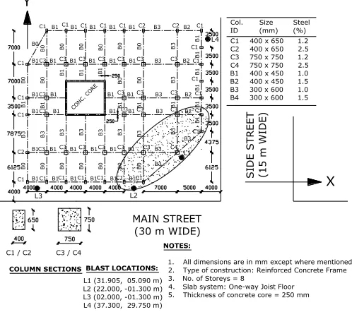
1. All dimensions are in mm except where mentioned. 2. Type of construction: Reinforced Concrete Frame 3. No. of Storeys = 8
4. Slab system: One-way Joist Floor 5. Thickness of concrete core = 250 mm C3 / C4
C1 / C2
COLUMN SECTIONS CONC . CO RE L1 L4 L2 L3
L1 (31.905, 05.090 m) L2 (22.000, -01.300 m) L3 (02.000, -01.300 m) L4 (37.300, 29.750 m) BLAST LOCATIONS: X Y C1 C2 C1 C1 C1 C1 C3 C3 C3 C3
C1 C1 C1 C1 C1 C2 C2 C1
C1 C1 C1 C3 C3 C3 C3 C3 C3
C3 C3 C3 C1
C1 C3 C3 C3 C4 C3 C3 C3 C3 C3
C1 C1 C1 C1 C1
C1
B1 B1 B1 B1 B1 B1 B1 B1 B1 B1 B1 B1 B3 B1 B1 B1 B1 B3 B2 B1 B1 B1 B1 B3 B2 B2 B3 B1 B1 B1 B1 B1 B1
B1 B1 B1 B1 B1 B3 B2 B0
B3 B3
B0
B3
B0 B0 B0 B0 B0 B0
B3 B3 B3 B3 B3 B3 B3
B1 B1 B1 B1 B1
B0 B0 B1 B1
B0 B0 B0 B0 B0 B0 B3
B1 B1 B1 B1 B1 B1 B3 B0 B0 B1
Col. Size Steel
ID (mm) (%)
C1 400 x 650 1.2
C2 400 x 650 2.5
C3 750 x 750 1.2
C4 750 x 750 2.5
B1 400 x 450 1.0
B2 400 x 450 1.5
B3 300 x 600 1.0
B4 300 x 600 1.5
Fig. 1. Layout of building with threat scenario for location L1
Although the building taken up for the investigation is similar to an existing structure, only general geometries and dimensions were used, whereas the reinforcement detail was obtained by first designing the structure based on the geometries. STAAD-Pro software with ACI 318 [1] was used in the design process. The beams and columns were represented by beam element and the concrete core was represented by shell element in the analysis. The foundation is assumed to be a thick RC raft. Thus, the columns are fixed at the base. The uniaxial cylinder compressive strength of concrete used in the design is 40 MPa and the yield strength of steel is assumed to be 500 MPa. The section dimensions of various elements taken in the design are same as those obtained for the existing structure. The section dimensions and the corresponding percentage of reinforcement obtained for different groups of elements are shown in Fig. 1. The percentage of reinforcement in various members has been assumed to be typical for each storey. The percentage of steel adopted for beams is the average value. Based on the structural design, the percentage of horizontal and vertical steel in the concrete core is 1% each in both directions. The thickness of concrete core has been taken as 250 mm and the thickness of the typical concrete slab is 150mm.
A. Finite Element Model Description
The analysis was carried out using an explicit finite element code, LS-DYNA, a general purpose transient dynamic finite element program capable of simulating complex real world problems. LS-DYNA uses explicit time integration algorithms and updates the stiffness matrix based on geometry changes and material changes at the end of each load increment. Then a new stiffness matrix is constructed and the next increment of load (or displacement) is applied to the system.
Mesh Discretization
The finite element modeling was carried out in two stages – the local model stage to assess the performance of individual
columns against blast pressures and the global modeling stage to assess
the overall response of the structure due to
the failure of the critical columns.
The critical structural components are the perimeter columns in the vicinity of the Vehicle-Borne Improvised Explosive Devices (VBIED). Hence a typical column model was built in order to establish the vulnerability of the vertical component. Fig. 1 shows that there are four type of columns (C1, C2, C3 and C4) used in the building. The columns were modeled using hexahedronal solid elements, while the shear and longitudinal reinforcements of the columns were modeled as a discrete component using beam elements. 12mm diameter bars were used for ligatures at a 300mm spacing and 20mm diameter bars were used for the longitudinal reinforcement. The models for the two column sizes are shown in Figs. 2 and 3.
(a)Reinforcement details (b)Concrete model
Fig. 2. Local model of Columns C1/C2
(a) Reinforcement
details
(b) Concrete model
The structure geometry was built based on the available detailed drawings. In the global modeling phase, the elements of the structure were simplified into beam elements and shell elements whenever possible. Reinforced concrete columns and beams were modeled as 2-node axial beam elements with tension, compression, torsion and bending capabilities. The element has six degrees of freedom at each node – three translations and three rotations about the local Cartesian coordinate axes. This element allows a different unsymmetrical geometry at each end and permits the end nodes to be offset from the centroidal axis of the beam. A plane through three nodes defines the orientation of the principal plane of the beam. The element formulation theory used in the model was Hughes -Liu with cross-section integration. The columns are generally rectangular.
The concrete slabs were modeled using a four n ode quadrilateral and three node triangular shell elements. This element has both bending and membrane capabilities. Both in -plane and normal loads are permitted. The element has six degrees of freedom at each node – three translations and three rotations about the local Cartesian coordinate axes. Stress stiffening and large deflection capabilities are included in the material model. The element formulation theory used in the modeling of slab was Belytschko-Tsay theory. The shell is assumed to be perfectly flat and the local co-ordinate system originates at the first node of connectivity. Since the Belyttschko-Tsay element is based on perfectly flat geometry, warpage is not included in the model. All of the façade components were modeled as 4-node shell elements using the Belytschko-Tsay element formulation theory. The use of beam and shell elements for the modeling of the structure leads to an affordable model with reasonable accuracy.
The mesh discretization of shell is such that the aspect ratio of quadrilateral shell elements varies from 1.00 to 1.53, whereas, the minimum included angle for the triangular shell elements is more than 30 degrees. The maximum length of the side of a shell element is taken as 1.66 m. The finite element model of the structure contains a total of 12336 nodes leading to 73734 unrestrained degrees of freedom. The model has 16282 beam elements, whereas the number of shell elements representing RC core, RC slab and facade are 1024, 8496 and 1920 respectively. The column bases have been fixed at the level of raft slab. The blast load applied on the shell elements of outer walls gets transmitted to the frames through the common nodes. The completed global model is shown in Fig. 4.
Fig. 4 Finite element model of the building
Material Model
An important aspect of finite element modeling is the establishment of material constitutive models, which represent the real behaviour of the structure in question. The primary elements under consideration are the core structure, columns, floor slab and façade system. These critical elements performance analyses were performed with LS-DYNA finite element code (version 971). The material models in the LS-DYNA constitutive model library are more than capable of accurately simulating the actual material behaviour in the model.
The material used in the building is mainly reinforced concrete. The primary constitutive model applied was the Concrete Eurocode (EC2) material model, which is suitable for beam and shell elements. The Concrete EC2 material model is capable of representing plain concrete, reinforcement bars, and concrete with smeared reinforcement, which is predominantly used in the global model. The model includes tensile cracking behaviour, compressive crushing behaviour, and reinforcement yield, hardening and failure behaviour. The constitutive parameters for the different elements in the structure are summarized in Tables I and II.
TABLE I
CONSTITUTIVE MATERIAL P ARAMETERS FOR RC ELEMENTS
Structura
l
Element
Constitutiv
e model
Densit
y
(kg/m3
)
Comp.
strengt
h
(MPa)
T ensile
strengt
h
(MPa)
Young’
s
modulu
s of
steel
(GPa)
Yield
strengt
h of
steel
(MPa)
Concrete
columns
and
beams
Concrete
EC2 2500 40 2.53 200 400
Concrete
slabs
and core
Concrete
TABLE II
CONSTITUTIVE MATERIAL P ARAMETERS FOR FACADE ELEMENTS
Constitutive
model
Density
(kg/m3)
Young’s modulus
(GPa)
Poisson’s ratio
Yield
stress
(MPa) Failure
strain
Plastic
Kinematic 2500 2.50 0.2 2.0 0.002
B. Blast Scenario
The assessment of blast resistance of a building requires the definition of the level of threat. There are numerous possible threats, but this analysis considers the intentional explosion outside the building. The threat for a conventional bomb is defined by three equally important parameters, namely the type of explosive, charge weight and the standoff distance. There are many explosive devices such as Ammonium-Nitrate Fuel Oil (ANFO) mixture, TNT, C4, Semtex and so forth that may be used by terrorists, but to standardize the parameters, the charge weight of an explosive device is expressed in terms of equivalent TNT weight. Thus there are only two parameters to be considered in the blast analysis i.e. the charge weight and the standoff distance.
The layout of the building is rectangular in plan with chamfered South West (SW) corner. The main entrance and exit of the building is located in the SW corner. The building is located on the intersection of two major roads with the West and South faces of the building facing the roads. There is street-side parking on the South and West sides of the building, whereas the North and East side accesses are limited to pedestrian sidewalk. The major threat to the building from terrorist bombing is through explosion in a parked vehicle. The layout of the building and its surroun dings suggest that a vehicle may be parked close to the building on South or West faces of the building which are facing the roads. Thus the minimum standoff distance of the location of explosion for the building has been taken as 2.5 m. Four possible crit ical locations of explosion, as shown in Fig. 1, have been considered in the study.
The weight of explosive as TNT equivalent is taken as 1000 kg which is the weight that can be carried in van packed to its full capacity with explosives. The height of blas t above the ground has been taken as 1 m because the explosive is assumed to be detonated in a vehicle. Thus the shock transmitted to the building through ground gets diminished and subsequently neglected in this analysis.
C. Blast Load Application
In the analysis, the loads on the critical element have to be applied in two stages to account for both gravity load and blast loads. The gravity load was applied as a ramp loading function, and maintained constant once it had reached the peak gravity load level. The blast pressure was applied to the façade component of the structure using the in -built CONWEP function in LS-DYNA. Fig. 5 illustrates the load stages in the model.
Time (s)
Loa
d
Gravity Load
3.0
Blast Load
Fig. 5. Loading procedure for application of gravity and blast loads on global
model
D. Results and Discussion
Four potential different scenarios were suggested for the analysis as shown in Fig. 1. The selection of these scenarios depended upon the layout of the building with respect to the streets, the standoff-distance provided, and the available access to the building. The detailed results of the first threat scenario are presented in this paper.
The first threat scenario was selected in which, the 1000 kg charge was placed on the vicinity of the columns located at location L1 as shown in Fig. 1. The threat is located at 2.5m stand-off distance, which is the distance between the centre of the explosive and the building.
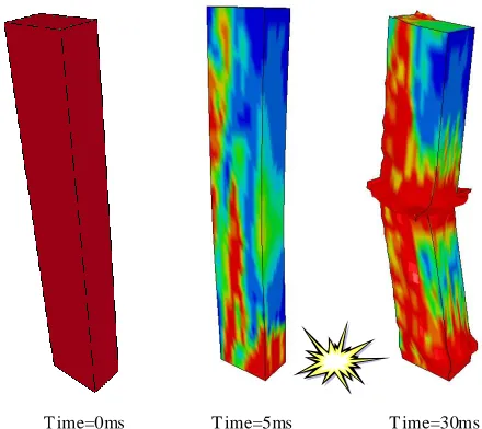
The results of local model analysis indicate that the seven columns shown enclosed in the elliptical shaded area will be severely damaged due to fragmentation of concrete and rupture of longitudinal as well as the transverse steel bars and eventually lost their load bearing capacity. The strike of flying debris on different parts of the structure has not been considered. Figures 6 and 7 show the typical damage of columns observed in the analysis.
T ime=0ms T ime=5ms T ime=30ms
T ime=0ms T ime=5ms T ime=30ms
Fig. 7. T ypical damaged column – C3/C4
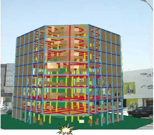
Figures 8 and 9 show the damage on the façade of the building and the structural system at progressive time after the arrival of the blast pressures. The structural damage in the event indicates partial collapse of the structure. Due to the loss of the columns in the vicinity of the blast event, the gravity load has to be transferred to adjoining vertical components such as the next columns and the core structure via flexural action of the floor slab. The partial collapse occurs because the flexural stresses exceed the flexural capacity of the floor slab. Hence, the floor slab is extensively damaged and, subsequently, lost its load transfer capacity. The slab damage is shown in Fig. 10. One important feature observed in the progressive collapse analysis of the structure is that the damage is only localized even after the removal of seven columns due to such a severe blast. This is primarily due to the presence of the reinforced concrete lift core.
Fig. 8. Damage state of building at 3.1s
Fig. 9. Partial collapse of the building at 6s
Fig. 10. Damages on the floor system of the building
IV. CONCLUSIONS
V. ACKNOWLEDGEMENT
The financial grant received from the Knowledge Exchange and Technology Transfer Program of King Saud University, Riyadh, KSA, for carrying out the present study is gratefully acknowledged.
REFERENCES
[1] ACI 318 (2008). “Building Code Requirement for Structural Concrete and Commentary,” American Concrete Institute, Farmington Hills, MI. [2] GSA (General Service Administration). Progressive collapse analysis and design guidelines for new federal office buildings and major modernization project; 2003.
[3] DOD (Department of defense). Unified facilities criteria, design of building to resist progressive collapse; 2005.
[4] BS 8110-1:1997. Structural use of concrete. Part 1: Code of practice for design and construction. British Standard Institute. 1997.
[5] Japanese society of steel construction council on tall building and urban habitat. Guidelines for progressive collapse control design; 2005. [6] Eurocode 1-Actions on structures. Part 1.7: General Actions - Accidental
actions. BS EN 1991-1-7, European Committee for Standardization, Brussels (2006).
[7] Allen, D.E. and Schriever, W.R., 1972, Progressive Collapse, Abnormal Load, and Building Codes, Structural Failure: Modes, Causes, Responsibilities, Proceedings American Society of Civil Engineers, New York.
[8] Breen, J.E. (1975). Research Workshop on Progressive Collapse of Building Structures held at the University of Texas at Austin, National Bureau of Standards, Washington, D.C.
[9] Griffiths, H., Pugley, A.G., and Saunders, O., 196 8, Report of T he Inquiry into The Collapse of Flat at Ronan Point, Canning T own, Her Majesty’s Stationary Office, London.
[10] Marjanishvili, S. and Agnew, E. (2006) “Comparison of Various Procedures for Progressive Collapse Analysis”, Journal of Performance of Constructed Facilities, 20(4), pp. 365 -374.
[11] Hinman, E. (2001) “Comparisons of Seismic and Blast Loading”, in Summary of NIST /GSA Workshop on Application of Seismic Rehabilitation T echnologies to Mitigate Blast -Induced Progressive Collapse, Ed. Carino, N.J. and Lew, H.S., Oakland, CA.
[12] Kaewkulchai, G. and Williamson, E.B. (2003) “Dynamic Behaviour of Planar Frames During Progressive Collapse”, Proc. 16th ASCE Engineering Mechanics Conference, University of Washington, Seattle, 16-18 July 2003.
[13] Kaewkulchai, G. and Williamson, E.B., 2006, “ Modelling the Impact of Failed Members for Progressive Collapse Analysis of Frame Structures”, Journal of Performance of Constructed Facilities, 20(4), pp. 375 -383. [14] Buscemi, N. and Marjanishvili S.M. (2005). “ SDOF Model for Progressive Collapse Analysis”. ASCE SEI Structures Congress, April 20-24, 2005, New York, NY
[15] Dusenberry, D. O. and Hamburger, R.O. (2006). “Practical Means for Energy-Based Analyses of Disproportionate Collapse Potential”, Journal of Performance of Constructed Facilities, 20(4), pp. 336-348. [16] Nair, R.S. (2006). “Preventing Disproportionate Collapse”, Journal of
Performance of Constructed Facilities, 20(4), pp. 309 -314. [17] Ellingwood, B. and Leyendecker, E.V. (1978). “Approaches for Design
Against Progressive Collapse,” Journal of the Structural Division, ASCE, Vol. 104, No. ST 3, pp. 413 -423
Tare k H. Almusallam. T his author is working as Professor of Structural Engineering at College of Engineering, King Saud University, Riyadh,, Saudi Arabia since 2007. He earned his B.S. degree in Civil Engineering from King Saud University, Riyadh, Saudi Arabia in 1984. He received his M.S. degree in Structural Engineering from the University of Colorado, USA in 1987. He got his Ph.D. degree in Structural Engineering from the University of Arizona, USA in 1991.
Hussein M. Elsanade dy. He is assistant professor of civil engineering at Helwan University, Cairo, Egypt, at present working with Specialty Unit for Safety and Preservation of Structures. He received his B.Sc. and M.Sc. from Helwan University, Cairo, Egypt and his Ph.D. in Structural Engineering from the University of California, Irvine, Calif., USA in 2002. His research interests include seismic retrofit and rehabilitation of concrete structures using
fiber reinforced polymer (FRP) composites, and failure analysis and damage assessment of buildings and bridges.
Tuan Ngo is Research Director of the Advanced Protective Technologies of Engineering Structure Research Group, Research Manager of the ARC Research Network for a Secure Australia at the University of Melbourne, Australia.