Abstract— This paper discusses PIC16F84A microcontroller
applications to interface with electronics display devices. It consists of hardware and software tools to provide the development and transfer of program code from a personal computer to the microcontroller and evaluation of its execution on hardware circuit design have been implemented. Firstly, the paper focuses on the information of PIC16F84A microcontroller, programming and simulation using Proteus software. Then, it presents electronic display devices interfacing and circuit designs. Throughout the paper, a special attention is given to the interfacing techniques of PIC16F84A framework using various types of display devices useful in the electronic engineering education process.
Index Terms— PIC16F84A; Programming; Simulation;
Engineering education process.
1) INTRODUCTION
Microcontrollers are useful to the many control applications that can be interfaced with other devices, such as sensors, motors, switches, keypads, displays and memory devices. Variety of interface methods have been developed to solve the complex problem of balancing circuit design criteria such as features, cost, size, weight, power consumption, reliability [1].
Many microcontroller designs typically combine multiple interfacing methods. In an unsophisticated form, a micro-controller system can be viewed as a system that reads from (monitors) inputs, performs processing and writes to (controls) outputs. The device is small, and controller suggests that the device can be used in control applications. Most of the microcontrollers are built into (or embedded in) the devices they control.
The name PIC initially referred to Peripheral Interface Controller, which is a family of microcontrollers made by Microchip technology. PIC microcontrollers take part in a essential role in electronic control systems. In this paper, PIC 16F84A has been implemented to interface with variety of display devices. There are some strong reasons that chosen to PIC 16F84A such as simple architecture, less amount of instructions etc. Figure (1) shows the PIC16F84A pin diagram.
The LEDs, 7-segment display and LCD are used as electronic display devices for displaying information in this paper. The PIC 16F84A belongs to the mid-range family of
Manuscript received January, 2019.
Myat Mon Thein, Electronic Engineering Department, Technological University (Sittwe), Sittwe, Rakhine State, Myanmar, Mobile No.+959421736170.
Kyaw Soe Lwin, Electronic Engineering Department, Technological University (Sittwe), Sittwe, Rakhine State, Myanmar, Mobile No.+9595062554.
the PIC microcontroller devices. It has 18- pins and comes in various packages. But we are only concerned with the PDIP (Plastic Dual Inline Package) which is normally used by hobbyists. Following are the specifications of the PIC16F84A [3]:
-Only 35 instructions- which makes it a popular RISC (Reduced Instruction Set Computer)
- Operating frequency- up to 20 MHz
- 1k x 14 bits flash EEPROM program memory - 68 x 8 bits data RAM
- 64 x 8 bits data EEPROM
- 16 special function registers (SFRs) - Operating voltage- 2.0 to 5.5 volts - Low power, high speed technology
Features:
- 13 I/O pins- You can configure the 13 pins either as input or output individually.
- Each pin can source/sink 25mA current. - Support ICSP (In Circuit Serial Programming). - Flash memory can be erased /written 10,006 times.
- EEPROM memory can be erased /written 10,000,000 times.
- Built in watchdog timer.
Figure 1: PIC16F84A and its pins description They are grouped into two groups. Port A which contains 5 pins (17,18, 1,2 & 3) and Port B which contains 8 pins (6,7,8,9,10,11,12 & 13). There are two memory types in the PIC 16F84A. These are the program memory and the data memory. Each memory has its own bus, so that access to each memory can occur during the same oscillator cycle. For the PIC 16F84A, the first 1k x 14 (0000h-03FFh) are physically implemented.
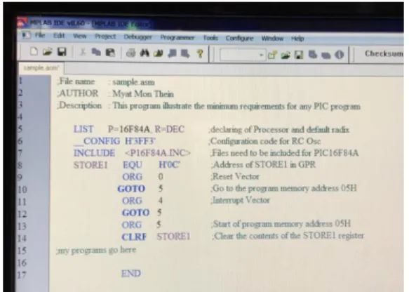
2) Applied Software to PIC Microcontroller Circuits Firstly, the programs are written in assembly language using MPLAB compiler software (shown in Figure 2). PICkit2 programmer software has utilized in order to transfers of program code from a personal computer to the microcontroller. The results of circuit design are simulated by Proteus software. An assembly language is the most-basic low-level programming language in which there is a very strong correspondence between the program’s statements and
Implementation of Electronic Display Devices
Interfacing Techniques
1
architecture’s machine code instructions. It requires less memory and execution time.
Figure 2: Using MPLAB Software
It allows hardware-specific complex job in an easier way. Data is represented in memory and other external devices in this language. Compilers and assemblers are used to converts both high-level languages and low-level (assembly) languages code into a compact machine code for storage in the PIC microcontroller’s memory. For the above reasons, assembly language is applied in this paper.
Figure 3 shows the Assembly program backbone of the MPLAB IDE Editor platform.
Figure 3: Assembly Program Backbone
Proteus Software has utilized for Modeling and circuit simulation purposes. It also has the ability to simulate the interaction between software running on microcontroller and any analog or digital electronic connected to it. These circuits are designed with the help of Proteus software.
Applied Hardware Devices and Components; -PC (Computer)
-PIC16F84A
-PICkit2 Programmer
-Breadboard and connection wires
-LEDs, 7-segment display, LCD, potentiometers, push button, oscillator, capacitors, resistor
PICkit2 Programmer
PICkit2 is a family of programmers for PIC microcontrollers made by Microchip Technology. It is used to program and debug microcontrollers.
Figure 4: Using Hardware Equipment
3) Interfacing Electronic Display Devices Display devices are the output devices for presentation of information in text or image form. Controlling can be done by interfacing these displays with the controlling devices such as microcontrollers.
Interfacing with Light Emitting Diode (LED)
In PIC microcontroller circuit, it is used for displaying the status of microcontroller pins. There are two ways by we can connect LEDs to microcontroller unit. Those two ways are active high logic and active low logic. Active high logic means LED will be ON when port pin is 1 and LED will be OFF when pin is 0. Active low opposes to active high. The program presents below has been written to interface LED display. In this program, implement has done by setting PORTB to output mode and turn-on each LED.
LIST P=16F84A, R=DEC
__CONFIG H'3FF3' ;Configuration code for RC Osc.
INCLUDE <P16F84A.INC>
#DEFINE BANK0 BCF STATUS, 5 #DEFINE BANK1 BSF STATUS, 5 COUNT EQU H'0C'
ORG 0 GOTO 5 ORG 5
CLRF COUNT ;Clear COUNT register CLRF PORTA ;Clear PORTA register CLRF PORTB ;Clear PORTB register BANK1 ;Select BANK 1
CLRF TRISA ;make all PORTA pins as outputs CLRF TRISB ;make all PORTB pins as outputs BANK0 ;Select BANK 0
GOTO LOOPIT
DELAY DECFSZ COUNT,F GOTO DELAY
RETURN
LOOPIT BSF PORTB,0 ;make RB0=1 to turn on LED LB0
CALL DELAY ;wait about 0.5 sec
BSF PORTB,1 ;make RB1=1 to turn ON LED LB1 CALL DELAY ;wait about 0.5 sec
BSF PORTB,2 ;make RB2=1 to turn on LED LB2 CALL DELAY ;wait about 0.5 sec
BSF PORTB,3 ;make RB3=1 to turn ON LED LB3 CALL DELAY ;wait about 0.5 sec
BSF PORTB,4 ;make RB4=1 to turn ON LED LB4 CALL DELAY ;wait about 0.5 sec
BSF PORTB,5 ;make RB5=1 to turn ON LED LB5 CALL DELAY ;wait about 0.5 sec
BSF PORTB,6 ;make RB6=1 to turn ON LED LB6 CALL DELAY ;wait about 0.5 sec
BSF PORTB,7 ;make RB7=1 to turn ON LED LB7 CALL DELAY ;wait about 0.5 sec
CLRF PORTB ;Clear PORTB to turn OFF all LEDs
CALL DELAY ;wait about 0.5 sec GOTO LOOPIT ;Repeat again END
Figure 5 shows the schematic diagram of the interfacing with LED. Figure 6 shows the simulation results (Right) and tested circuit (Left).
Micro-controller
P1.0 LED
+5V
Figure 5: Active low LED connection with PIC microcontroller pin
Figure 6: LED circuit design with Breadboard and Proteus software
Interfacing with Seven-Segment LED Display
In order to make event of up-counter using Common Cathode 7-segment display, following program is used to control a 7-segment display. The display is connected to PORTB. The program counts from 0 to 9 and then repeats each time a switch , connected to RA4 is pressed
LIST P=16F84A, R=DEC
__CONFIG H'3FF1' ;Configuration code for XT Osc.
INCLUDE <P16F84A.INC> ERRORLEVEL -302
#DEFINE BANK0 BCF STATUS,5 #DEFINE BANK1 BSF STATUS,5 COUNT EQU H'20' COUNT1 EQU H'21' COUNT2 EQU H'22' COUNT3 EQU H'23' ORG 0 GOTO 5 ORG 5 CLRF PORTA MOVLW B'00111111' MOVWF PORTB CLRF TRISB
MOVLW B'00010000' ;RA4 AS INPUT MOVWF TRISA
BANK0
BSF PORTA,0 ;Set RA0 to turn on Q1 GOTO MAIN COMCATHODE ADDWF PCL,F RETLW B'00111111' ;0 RETLW B'00000110' ;1 RETLW B'01011011' ;2 RETLW B'01001111' ;3 RETLW B'01100110' ;4 RETLW B'01101101' ;5 RETLW B'01111101' ;6 RETLW B'00000111' ;7 RETLW B'11111111' ;8 RETLW B'01101111' ;9
DELAY50 CLRF COUNT1 ;wait 50 ms WAIT1 DECFSZ COUNT1,F
GOTO WAIT1 DECFSZ COUNT2,F GOTO WAIT1 RETURN
GETKEY BTFSC PORTA,4 ;Is RA4 =0?, is S4 pressed?
GOTO GETKEY ;no
CALL DELAY50 ;yes, wait 50 ms LOOP BTFSS PORTA,4 ;is RA0=1?, is S1 released?
GOTO LOOP ;no-check again CALL DELAY50 ;yes-wait 50 ms
INCF COUNT,F ;COUNT=COUNT + 1 MOVF COUNT,W ;COUNT -->W ADDLW 6 ;W= W + 6
BTFSC STATUS,DC ;is DC = 0? CLRF COUNT ;no-Clear COUNT
OUTPUT MOVF COUNT,W;yes- COUNT -->W CALL COMCATHODE ;Read COMANODE table MOVWF PORTB ;W -->PORTB
GOTO GETKEY ;Repeat again END
Figure 7 shows the schematic diagram of the interfacing with seven segment display. Figure 9 shows the simulation results using Proteus software and Figure 8 shows tested circuit. PIC16F84A RB6 RB5 RB4 RB3 RB2 RB1 RB0 K a b c d e f g Common Cathode PIC16F84A RB6 RB5 RB4 RB3 RB2 RB1 RB0 a b c d e f g +5V Common Anode A
Figure 7: Interfacing common cathode and common anode 7-segment with PIC
Figure 8: Seven-segment circuit design with Breadboard
Interfacing with Dot Matrix LED Display
Interfacing can be done for LED matrix display with a microcontroller. Programming for the Dot Matrix has been done. Figure 10 shows the simulation results using Proteus software and tested circuit.
Figure 10: Interfacing the LED (7-segment) matrix display with PIC
Interfacing with Liquid Crystal Display (LCD)
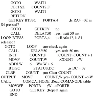
LCDs are specially designed for specific applications to display graphic images. It is having three selection lines and 8 data lines. By connecting the three selection lines and data lines with the microcontroller, the message can be displayed on LCD. Following program is the Assembly code for displaying a message on LCD Line1 using 8-bit Interface. LIST P=16F84A, R=DEC
__CONFIG H'3FF3' ;Configuration code for RC Oscillator
INCLUDE <P16F84A.INC> ERRORLEVEL -302
#DEFINE BANK0 BCF STATUS,5 #DEFINE BANK1 BSF STATUS,5 CBLOCK H'0C' CNT1 DELAY1 DELAY2 ENDC ORG 0 GOTO 5 ORG 5 CLRF CNT1 CLRF DELAY1 CLRF DELAY2 CLRF PORTA CLRF PORTB BANK1 CLRF TRISA CLRF TRISB BANK0 GOTO LONGDEL
FUNC_SET BCF PORTA,2 ;RA2=RS=0 BCF PORTA,1 ;RA1=R/W=0 MOVLW B'00111000'
MOVWF PORTB CALL SHORTDEL
DISPLAY_ON BCF PORTA,2 ;RA2=RS=0 BCF PORTA,1 ;RA1=R/W=0 MOVLW B'00001111' MOVWF PORTB CALL PULSE_E CALL SHORTDEL CLRF CNT1 MESSAGE MOVF CNT1,W CALL TEXT_TABLE BSF PORTA,2 ;RA2=RS=1 BCF PORTA,1 ;RA1=R/W=0 MOVWF PORTB CALL PULSE_E CALL SHORTDEL INCF CNT1,W XORLW 14 BTFSC STATUS,Z GOTO STOP INCF CNT1,F GOTO MESSAGE STOP GOTO STOP
SHORTDEL DECFSZ DELAY1,F GOTO SHORTDEL
RETURN
PULSE_E BSF PORTA,0 ;RA0=E=HIGH NOP
BCF PORTA,0 ;RA0=E=LOW RETURN
TEXT_TABLE ADDWF PCL,F
RETLW 'M' ;ASCII CODE FOR W RETLW 'Y' RETLW 'A' RETLW 'T' RETLW 'M' RETLW 'O' RETLW 'N' RETLW ' ' RETLW 'T' RETLW 'O' RETLW ' ' RETLW 'P' RETLW 'I' RETLW 'C' END
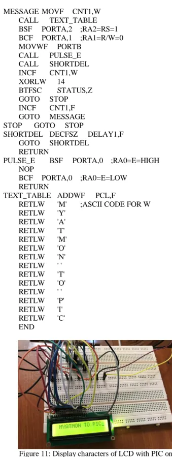
Figure 11: Display characters of LCD with PIC on breadboard
Figure 12: Display characters of LCD with PIC by Proteus software
As shown in Figure 11, the three selected lines EN, R/W, RS will be used for controlling the LCD display. EN pin uses for enabling the LCD display for communicating with microcontroller. RS pin uses for register selection. R/W control line is low, the information on the data bus is being written to the LCD. When R/W is high, the program is effectively reading the LCD. R/W line will always be low. Figure 12 shows display characters of LCD with PIC by Proteus software.
4) CONCLUSION
Microcontrollers are useful to interface with I/O devices. LEDs, LCDs and seven-segment displays devices are interfaced. Many interfacing techniques have been developed to solve the complex problem for communicating with displays. Varieties of design techniques are interfaced using software and hardware implementations. The results of the paper show clear outcomes that make implementation more flexible and applicable to control systems that are found in the electronic education.
ACKNOWLEDGMENT
First of all, the authors would like to express their special thanks to Dr. Myo Thein Gyi, Union Minister of Education, the Republic of the Union of Myanmar, for his encouragement to do research works for regional development and applied science. The authors’ grateful thanks go to Dr. Kyaw Hlaing Oo, Acting Pro-Rector and Principal of Technological University (Sittwe) for his kind guidance, suggestion and directions throughout the preparation of research work, and valued motivations and encouragement as well. Finally, the authors are also sincerely thankful to our colleagues from the Department of Electronic Engineering, Technological University (Sittwe) offered strong moral and physical support.
REFERENCES
[1] http://www.bipom.com, Microcontroller Interfacing Techniques [2] http://www.mstracey.btinternet.co.uk/index.htm, PIC Programming in
Assembly
[3] Tim Wilmshurst, Designing Embedded Systems with PIC Microcontrollers (Principles and Applications)
[4] https://ww1.microchip.com/devicedoc, PIC16F84A Data Sheet-Microchip Technology.
Myat Mon Thein has received her B.E. degree in Electronic Engineering (in 2002) from Mandalay Technological University, M.E. degree in Electronic Engineering (in 2004) from Yangon Technological University. She is dedicated to teaching field from the last 18 years. She has supervised fourteen under graduate students. Her research areas are electronic circuit design and Network Design. At present she is working as lecturer of Electronic Engineering Dept. at Technological University (Sittwe), Rakhine State, Myanmar.
Kyaw Soe Lwin has received his B.E. degree in Electronic Engineering (in 2002), M.E. degree in Electronic Engineering (in 2004) from Yangon Technological University and Ph.D. degree in Electronic Engineering (in 2009) from Mandalay Technological University. He is dedicated to teaching field from the last 16 years. He has supervised 25 M.E students, guided 5 Ph.D. students and 50 under graduate students. His research areas are power electronics, electronic circuit design (including VHDL) and RF and Microwave Circuit Design. At present he is working as Professor and Head of Electronic Engineering Dept. at Technological University (Sittwe), Rakhine State, Myanmar.