32nd Annual Trenton Computer Festival
28 – 29 April 2007, Ewing Township, New Jersey.
Microcomputer Based Electronics: Using the C Stamp™ in
Pre-Engineering, Technology, and Engineering Programs
Orlando J. Hernandez
The College of New Jersey, Ewing, New Jersey, U.S.A., [email protected] A-WIT Technologies, Inc., Williamstown, New Jersey, U.S.A., [email protected]
A
BSTRACTThis paper describes the usage of a microcomputer platform that can serve both recruitment and retention purposes. This platform can be deployed in both secondary and higher education, including technology programs, to address the chasm that exists in educational tools usage in those two educational environments. The paper concentrates in describing how to conduct and develop electronics projects with the C Stamp™ microcomputer module.
Keywords: C Language, Engineering Education, Microcomputers, Microcontrollers, Pre-Engineering Education
1.
I
NTRODUCTIONIn recent years, the issue of retention in Engineering Education programs has taken a forefront position relative to the issue of recruitment. Many efforts are under way to try to improve engineering education retention through programming as a form of collaborative learning. This paper describes the usage of a microcomputer platform that can serve both recruitment and retention purposes. This platform can be deployed in both secondary and higher education, including technology programs, to address the chasm that exists in educational tools usage in those two educational environments. The paper concentrates in describing how to conduct and develop electronics projects with the C Stamp™ microcomputer module. C Stamp modules are very affordable and capable microcomputers (self contained single chip computers) that are designed for use in a wide variety of projects. The paper presents hardware aspects of the C Stamp, as well as programming, various input/output techniques, and functional commands available to make project development and student experience most rewarding; all with professional tools, and with a focus on Digital Control, Signal Processing, and Mechatronic applications.
Each C Stamp comes with a microcontroller chip that contains the C Stamp Operating System, internal memory (RAM, EEPROM, and Flash), a 5-volt regulator, a number of general-purpose I/O pins (TTL-level and Schmitt Trigger inputs, and 0-5 Volts outputs), communication and other peripherals, analog functions, and a set of library function commands for math, pin operations, and much more. C Stamp modules are capable of running many thousand instructions per second and are programmed with a subset of the C programming language, called WC. WC is a simple, easy to learn language, and it is highly optimized for embedded system. It includes many specialized functions. The manual includes an extensive section devoted to each of the available functions.
The Electrical Engineering Program at the Milwaukee School of Engineering (MSOE) has implemented a new introductory electrical engineering (EE) course in the first quarter of the freshman year. Student retention is the primary motivation, and the special manner in which the course is team-taught helps to ensure the desired student satisfaction. Initial feedback has shown that the students are excited to experience the breadth and flexibility of EE by understanding how familiar, everyday electronic items work. A pass/fail type grading system lessens student first-term stress, while encouraging participation and no-risk experimentation.
engineering, and computer intelligence to the design of products or systems. The mechatronics course at Bucknell consists of mechanical and electrical engineering students at the senior and graduate levels. The students engage in a variety of activities in teams comprised of members from each of these groups. In addition to team laboratory exercises and homework assignments, the students work in interdisciplinary groups to process their efforts. That is, they engage in meaningful discussion among themselves concerning their activities and the implications of the various results. The students also act as teachers by preparing lectures and exercises on topics from their discipline to the students in the cross discipline. Specifically, the electrical engineers teach the mechanical engineers microcontrollers, and the mechanical engineers teach the electrical engineers mechanisms.
2.
T
HEC
S
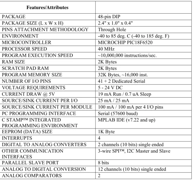
TAMPThe table below, Table 1, provides the specifications of the CS110000 C Stamp module.
Table 1: C Stamp Module Specifications
Features/Attributes
PACKAGE 48-pin DIP
PACKAGE SIZE (L x W x H) 2.4" x 1.0" x 0.4" PINS ATTACHMENT METHODOLOGY Through Hole
ENVIRONMENT -40 to 85 deg. C (-40 to 185 deg. F)
MICROCONTROLLER MICROCHIP PIC18F6520 PROCESSOR SPEED 40 MHz
PROGRAM EXECUTION SPEED ~10,000,000 instructions/sec.
RAM SIZE 2K Bytes
SCRATCH PAD RAM 2K Bytes
PROGRAM MEMORY SIZE 32K Bytes, ~16,000 inst. NUMBER OF I/O PINS 41 + 2 Dedicated Serial VOLTAGE REQUIREMENTS 5 - 24 V DC
CURRENT DRAW @ 5V 19 mA Run / 0.7 uA Sleep SOURCE/SINK CURRENT PER I/O 25 mA / 25 mA
SOURCE/SINK CURRENT PER MODULE 100 mA / 100 mA per 4 I/O pins PC PROGRAMMING INTERFACE Serial (57600 baud)
C STAMP™ INTEGRATED
PROGRAMMING ENVIRONMENT
MPLAB IDE (v7.22 and up) EEPROM (DATA) SIZE 1K Byte
INTERRUPTS 4 DIGITAL TO ANALOG CONVERTERS 2 channels (10 bits) single ended OTHER COMMUNICATION
INTERFACES
3-wire SPI™, I2C Master and Slave PARALLEL SLAVE PORT 8 bits
ANALOG TO DIGITAL CONVERSION 12 channels (10 bits) single ended ANALOG COMPARATORS 2
All C Stamp models come in Industrialrated versions, with an environmental temperature tolerance range of -40°C to +85°C.
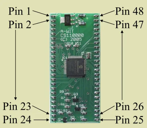
Pin 1
Pin 2
Pin 48
Pin 47
Pin 23
Pin 24
Pin 26
Pin 25
Pin 1
Pin 2
Pin 48
Pin 47
Pin 23
Pin 24
Pin 26
Pin 25
Figure 1: C Stamp Microcontroller3.
B
OARD OFL
EARNINGThe C Stamp is complemented by the CS310X00 (μC 101) Microcontroller Fundamentals Board of Learning (BOL). The Microcontroller Fundamentals Board of Learning (BOL) is a complete, high performance, low cost development platform designed for those interested in learning and using A-WIT’s C Stamp module. Its size, rich feature set, and low price make it an ideal tool for the student and educator. The μC101-BOL is a great tool with which to get started with A-WIT’s C Stamp modules. For educators, the μC101-BOL provides a clean and efficient platform to teach students the basics of microcontrollers, where they can easily plug in parts, and perform A-WIT provided projects or educator developed C Stamp based curriculum. The list below provides the specifications of the CS310X00 BOL.
• 2.0 mm center-positive plug that accepts different outer diameters for 5 to 24 V DC power supplies and 9 V battery connections; electronically interlocked to prevent dual connections, while both the power supply and battery can be present on the board at the same time. With the BOL having the breadboard toward you, if the switch is to the left, then the battery will be supplying the power. If the switch is to the right, then the external power supply will be supplying power.
• Independent 1 A high current power (VHC) generated on board for servos or other components that require more current than what the C Stamp can provide in large projects.
• No jumpers required for configuration.
• Serial (DB-9) connector for C Stamp IC programming and serial communication during runtime.
• Female 10-pin dual row connector for additional connections.
• Four servo connectors pre-connected to VHC, GND, and C Stamp I/O pins for control.
• RESET button with high tactile feedback.
• START button with high tactile feedback. START button can be used as a utility button during run time.
• Additional utility button with high tactile feedback.
• Eight utility green, high intensity, general purpose Light Emitting Diodes (LEDs).
• C Stamp power indicator LED.
• Mechanical Dimensions:
o PCB: 7.50" x 5.28"
o MOUNTING HOLES: 7.00" x 4.78"
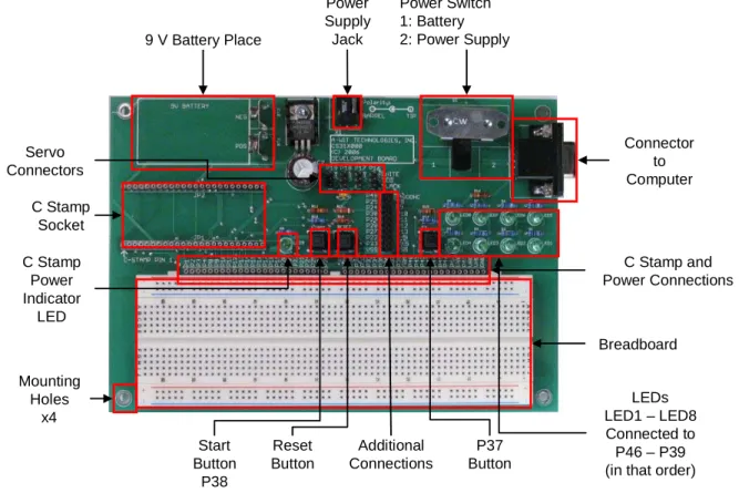
The figure below, Figure 2, shows the CS310X00 BOL with all features highlighted.
Power Supply Jack 9 V Battery Place Power Switch 1: Battery 2: Power Supply Servo Connectors Connector to Computer Breadboard C Stamp and Power Connections C Stamp Socket Additional Connections Reset Button Start Button P38 P37 Button C Stamp Power Indicator LED LEDs LED1 – LED8 Connected to P46 – P39 (in that order) Mounting Holes x4 Power Supply Jack 9 V Battery Place Power Switch 1: Battery 2: Power Supply Servo Connectors Connector to Computer Breadboard C Stamp and Power Connections C Stamp Socket Additional Connections Reset Button Start Button P38 P37 Button C Stamp Power Indicator LED LEDs LED1 – LED8 Connected to P46 – P39 (in that order) Mounting
Holes x4
4.
P
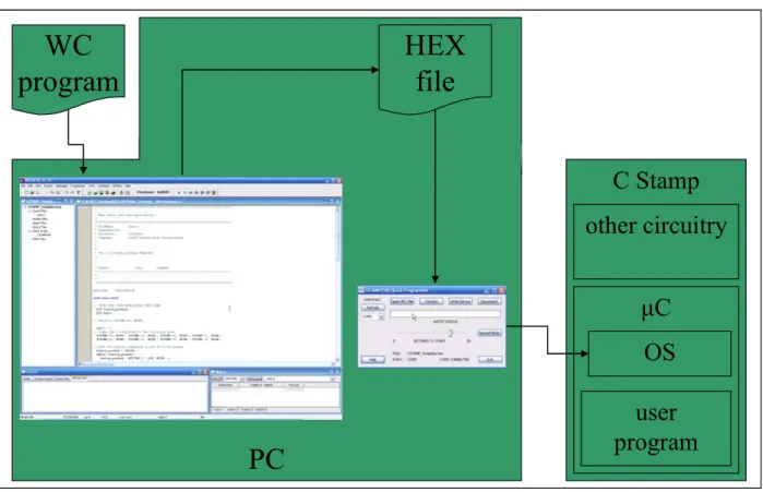
ROJECTSDeveloping programs and projects with the C Stamp is easy. Simply input the WC program into the professional Integrated Development Environment (IDE), and compile into a HEX file. Then use the programming software to download the program to the C Stamp. The program can then be executed in the C Stamp anywhere. Figure 3 below shows the program development flow with the C Stamp.
WC
program
PC
C Stamp
μ
C
other circuitry
user
program
OS
HEX
file
WC
program
PC
C Stamp
μ
C
other circuitry
user
program
OS
HEX
file
Figure 3: Program Development Flow
The following is an example of how programs written for the C Stamp look. It can be seen that students gain experience in C via WC program, while working with a software infrastructure that is very user friendly. This program starts by lighting all 8 LEDs in the BOL, and waits for the utility button at pin 37 to be pushed and let go (cycled). When this is done, then the program blinks 4 of the 8 LEDs in the BOL. Any time the utility button is cycled, the program switches to blinking the other four LEDs alternating the blinking of the LEDs between each bank of 4 LEDs. The program executes indefinitely until it is restarted it by pushing the RESET button while holding the START button and then letting go of the latter. In the code below, the keywords of the language have been bolded.
void main (void){
BIT button_pushed, half; // Declare some necessary variables half = 0; // Denotes which half (4 LEDs) of the 8 LEDs blinks // Light LED's connected to the following pins
STPIND(46, 1); STPIND(45, 1); STPIND(44, 1); STPIND(43, 1); STPIND(42, 1); STPIND(41, 1); STPIND(40, 1); STPIND(39, 1); // Wait for button connected to pin 38 to be pushed
button_pushed = FALSE; while(!button_pushed){
button_pushed = FALSE;
while(1){ // Check if button is pushed every second button_pushed = BUTTON(38, LOW, HIGH, 1);
if (button_pushed){ button_pushed = FALSE; if (half == 0) half = 1; else half = 0;
}
// Set one half of the LEDs to LOW, and toggle the other if (half == 0){
STPIND(42, 0); STPIND(41, 0); STPIND(40, 0); STPIND(39, 0); TOGGLE(46); TOGGLE(45); TOGGLE(44); TOGGLE(43);
}else{
// Set the other half of the LEDs to LOW, and toggle the other STPIND(46, 0); STPIND(45, 0); STPIND(44, 0); STPIND(43, 0); TOGGLE(42); TOGGLE(41); TOGGLE(40); TOGGLE(39);
} } }
5.
C
ONCLUSIONThis paper describes a comprehensive C based platform used in the Freshman Engineering Design Experience at TCNJ. With this platform, students receive a solid foundation in micro-controller based design. The goal is to provide student with powerful learning experiences that they can easily transfer to a future workplace.
R
EFERENCESA-WIT Technologies, Inc. “C Stamp Syntax and Reference Guide Manual”. v 1.5. A-WIT Technologies, Inc. “CS310XXX (μC 101) Reference Guide Manual”. v 1.0.
McDowell, C., Werner, L., Bullock, H. E., Fernald, J. (2006). “Pair programming improves student retention, confidence, and program quality”. Communications of the ACM, Vol. 49, No. 8, Music Information Retrieval,
pp. 90-95.
Reyer, S., Wrate, G., Wheeldon, J., Petersen, O. (2002). “Freshman electrical engineering course addressing retention and career choice”. ASEE Annual Conference Proceedings, 2002 ASEE Annual Conference and
Exposition: Vive L'ingenieur, pp. 9427-9432.
Shooter, S., McNeill, M. (2002) “Interdisciplinary collaborative learning in mechatronics at Bucknell University”.
Journal of Engineering Education, Vol. 91, No. 3, pp. 339-344.
Biographical Information
Orlando J. Hernandez received his Ph.D. degree in Electrical Engineering from Southern Methodist University in 2002. He is currently an Assistant Professor of Electrical and Computer Engineering, and the Director of the National Science Foundation sponsored Image Processing & Understanding Lab, and the Computer Architecture & VLSI Lab at the College of New Jersey, Ewing, New Jersey.
Authorization and Disclaimer
Authors authorize TCF to publish the paper in the conference proceedings. Neither TCF nor the editors are responsible either for the content or for the implications of what is expressed in the paper.