SonMicro Electronics Revision A.2 Feb, 2009
I2C 2.8 Communication Protocol
SM130
SM130 - Mini
SonMicro Electronics Revision A.2 Feb, 2009
1. INTRODUCTION
This application note explains I2C communication protocol with SM130 or SM130-Mini
Mifare module based on the I2C 2.8 firmware version. Factory programmed modules
have the UART version (UM x.x) therefore for I2C application Mifare module needs to be
flashed/upgraded with I2C 2.8 firmware version or later. Upgrade process is easy and free
of charge. Necessary tools can be requested by contacting us at
[email protected]
1.1 I2C 2.8 Firmware
I2C 2.8 firmware still supports the UART communication, but is limited, allows user to
demonstrate or test the system with PC software (i.e. SMRFID Mifare) or upgrade the
module. If the main communication protocol to be used is UART then user need to flash
UART version (UM x.x) of the firmware to support all commands.
The main difference of the I2C 2.8 version from the UM 1.x version is;
-
After reset, firmware version command is not sent.
-
After reset, module starts with “Seek for Tag” operation automatically.
-
Output OK pin indicates if “Seek for Tag” command is running or not.
-
Output1 pin is used as “Data Ready Pin” and can be useful to detect the Tag
whenever it enters into the RF field provided that “Seek for Tag” command was
previously running. Therefore controlling Output1 with the relevant command is
disabled, but Output2 can still be controlled.
-
Output Error pin will “pulse” whenever a tag enters into the RF Filed if the “Seek for
Tag” command was previously running. It is useful to trigger an external device or
drive a buzzer circuit, or simply drive a LED to indicate a Tag is found.
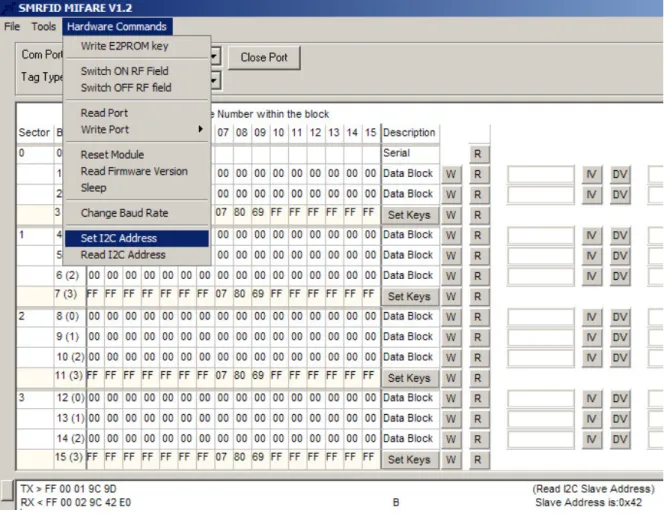
A new feature comes with I2C 2.8 firmware, that is ability to read and change slave
address. These commands can be called over UART and is supported on SMRFID Mifare
V1.2 PC Software.
Code Command Description
0x9B Change I2C Address Changes the I2C Slave Address
0x9C Read I2C Address Reads the I2C Slave Address
Table 1 – New UART commands comes with I2C 2.8 firmware version
PLEASE NOTE THAT:
The Default 7-bit I2C Slave Address is 0x42. However, just after first upgrade in customer
field, this address can be arbitrary (Most time 0x30) depends on the flash memory
content. Thus it is required that user should read and know I2C Slave address, or set
his/her own slave address before start on the application. Examples in this application
note will assume the slave address is 0x42(66 decimal)
To read or modify I2C Slave address, SMRFID Mifare V1.2 Software can be used. Please
look for Hardware Commands section in the Software.
SonMicro Electronics Revision A.2 Feb, 2009
1.1.1 Change I2C Slave Address
For detailed UART communication protocol, please investigate device datasheet.
UART Example Command:
FF 00 02 9B 42 DF
Set new I2C Slave Address to 0x42
Example Responses:
FF 00 02 9B 4C E9
0x4C ‘L’ indicating that Slave Address was set successfully
1.1.2 Read I2C Slave Address
For detailed UART communication protocol, please investigate device datasheet.
UART Example Command:
FF 00 01 9C 9D
Read I2C Slave Address
Example Responses:
FF 00 02 9C 42 E0
0x42 is the I2C Slave Address
SonMicro Electronics Revision A.2 Feb, 2009
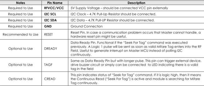
1.2 Module – I2C Pins
Figure 2 – SM130 PinOut View
Notes Pin Name Description
Required to Use RFVCC/VCC 5V Supply Voltage – should be connected VCC pin externally Required to Use I2C SCL I2C Clock – 4.7K Pull-Up Resistor should be connected. Required to Use I2C SDA I2C Data – 4.7K Pull-UP Resistor should be connected.
Required to Use GND Ground Connection
Recommended to Use RESET Reset Pin. In case a communication problem occurs that Master cannot handle, a hardware reset pin might be useful.
Optional to Use DREADY
Data Ready Pin. Functional if the “Seek For Tag” command was executed previously. A Logic 1 pulse will be sent as soon as valid Mifare Tag enters into the RF Field. Useful to generate interrupt on Master MCU instead of polling I2C
continuously.
Optional to Use TAGF
Same as Data Ready Pin but with longer pulse. This pin can trigger external device, drive buzzer circuit or simply can be connected to LED indicating there is a valid tag in the field
Optional to Use CREAD
This pin indicates status of “Seek for Tag” command. If it is logic high, then it means the Continuous Read (“Seek For Tag”) is active and module is searching for Mifare Tag continuously.
SonMicro Electronics Revision A.2 Feb, 2009
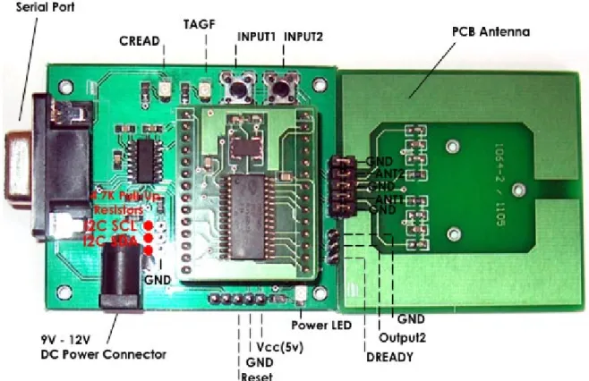
1.3 SM1013 Evaluation Kit (SM130-EK) – I2C Pins
SonMicro Electronics Revision A.2 Feb, 2009
2.
I2C COMMUNICATION PROTOCOL
SM130 have two communication interfaces; UART and I2C (as slave). Commands are
kept same for both protocols and even the frames are similar but not same. For
command details and UART communication protocol please investigate device
datasheet.
UART and I2C version comes with different firmware. Although I2C firmware supports
basic UART commands, users need to use UM x.x firmware version if the UART
communication is going to be used for the application.
SM130 can support clock rates up to 400 KHz. The address of the SM130 I2C slave is set to
0x42 as default. However, for customers upgrading I2C firmware version at the field for
the first time, need to set I2C address. SMRFID Mifare V1.2 software support
changing/reading I2C Slave address over UART/RS232.
Please notice that, in I2C 2.8 firmware version, module starts with “Seek for Tag”
command executed automatically. If the user does not use this feature then it can be
disabled. Any command sent from Master will disable “Seek for Tag” command. For this
purpose user can use HALT command to end the “Seek for Tag” operation.
SonMicro Electronics Revision A.2 Feb, 2009
2.1 I2C Command/Response Frame
The following is the I2C frame of the data packets sent by the I2C Master:
Length Command Data CSUM
1 Byte 1 Byte N Bytes 1 Byte
Table 3 – I2C Command frame send by I2C Master Device
1.
Length:
This byte is used to indicate the length of the payload data. This includes the
command and the data bytes. Checksum is excluded.
2.
Command:
This byte is used to instruct the module on what operation to perform
3.
Data:
These are parameters necessary for the module to execute the command. For
example, for a Read command, the data will be the block number to be read. For a
Write command, this will be the block number and 16 bytes of data.
4.
CSUM:
This is the checksum byte. This byte is used on the host as well as the module to
check the validity of the packet and to trap any data corruption. This is calculated by
adding all the bytes in the packet.
As soon as the module receives the complete command frame, it starts executing the
command. When the module executes the command, if the Master reads from the
module, the value returned will be 0x00. When the command execution is complete, the
length of response will be returned. Once the Master knows the length of response, it
should read the further response with the explained method.
Following is the I2C frame of the data packets sent by Slave (SM130) in response to the
commands:
Table 4 – I2C Response frame send by SM130 module (Slave)
1.
Length:
This byte is used to indicate the length of the payload data. The master
should first analyze this byte and then consequently read the number of bytes
indicated by this byte.
2.
Command:
This is the command for which the response is being sent back
3.
Response:
This contains the result data if an operation was successful or the error
code if the operation was not successful. The status of the operation can be found by
the length of the data bytes. For example, if the data length is 16 when a read
command is executed, it means that the operation was successful. If the data length
is 1, then it means that the read was not successful and the nature of the Error can be
found out by analyzing the Error code sent, which is the single data byte. The details
of the response length and error codes for each command can be found in device
datasheet.
4.
CSUM:
This is the checksum byte. This is the sum of all bytes.
Length Command Response CSUM
SonMicro Electronics Revision A.2 Feb, 2009
2.2 Tips & Important Notes
There are some important procedures needs to be known by the user.
1.
50 Millisecond Rule
The expected response prepared by SM130 will be preserved for only 50
milliseconds. In other words, when user sends a command, he/she has 50
milliseconds to read that response. The command still will be executed no
matter master read relevant response or not. Therefore users need to pay
attention when debugging and using break points not to miss the expected
response.
After around 50 milliseconds, SM130 will initialize 1 byte buffer and put it zero to
let know the Master there is no response ready to be sent.
2.
I2C Stop Condition – The Last Byte Read
The last byte read just before the i2c_stop condition needs to be done by
NACK’ed read. For most MCU compliers, this has a representation as
“i2c_read (0)”
3.
Polling/Read Frequency of a Response
It is recommended that user wait around 5 to 10 milliseconds to get response
from SM130 after a command is sent. This is to give time to SM130 make its
operations with less interrupt. Moreover, when checking continuously for a
“ready response” from SM130, use some delay (i.e. 5ms) between each read.
4.
I2C Slave Address
Default slave address is 0x42 for the I2C 2.8 firmware. However, if the module
was not programmed in the factory and upgraded at customer location, then it
should be set with SMRFID Mifare V1.2 software.
SM130 I2C uses 7-bit addressing. Therefore a shift operation is required when
accessing from an 8-bit I2C address mode Master device.
Shift one bit left
0x42
0x84
I2C Write Operation
0x84
SonMicro Electronics Revision A.2 Feb, 2009
2.3
Example Command and Response
Following is a descriptive example for I2C application. Read Firmware Version
command is used as an example.
READ FORMWARE VERSION” COMMAND WILL BE SEND
- Create a Start Condition and write address
For access from Master supports 8-bit I2C addressing, for 0x42 SM130 Address; Use 0x84 When writing to Master
Use 0x85 When reading from Master
In this example, we will send Read Firmware Version command We need to write this command to SM130
i2c_start(); Start Condition
i2c_write(0x84); Slave Address. Remember when writing we will use 0x84
- Send proper frame as explained in Section 2.1
Write I2C Frame
i2c_write(0x01); Length of the Data. Include Command ID, exclude Checksum byte
i2c_write(0x81); Command ID of Read Firmware Version Command
i2c_write(0x82); Checksum Byte. Checksum of the entire frame (Length + Data)
- Create a Stop Condition
i2c_stop(); Send Stop
SonMicro Electronics Revision A.2 Feb, 2009
NOTE THAT WE HAVE around 50ms to Read the Response!
- Read one byte from the Slave. If non-zero get the entire frame.
Make sure we have a delay before reading the response. Also for each read attempt we need to use delays not to disturb SM130 unnecessarily.
The first non-zero byte will indicate us that there is a response with that length.
We will try to read expected response 10 times as an example each read attempt With 5ms delay
for(i=0;i<10;i++) {
delay_ms(5); For each read attempt we will wait for 5ms
i2c_start(); Start Condition
i2c_write(0x85); Slave Address. Remember when reading we will use 0x85
Now we will read one byte from the slave. It shows us how many more bytes needs to be read. Zero means there is no ready response. Non-zero count means we need to read that much
Count = i2c_read(); Notice that we read with ACK same as i2c_read(ACK)
If (Count==0) {
We don’t have valid response yet. Because Count is zero. In the for loop we will read again after 5ms delay. Remember that we need to read last byte with NAK
i2c_read(0); Read with NAK before stop
i2c_stop();
} else {
We have non-zero Count byte. SM130 might prepare the response. Make sure the count is not greater than 18.
SM130 have no response greater than 18 .
This check is necessary because improper I2C system can generate 0xFF here! If (Count>18)
{
Do something here. For example reset Count and send Error Code
}
It looks like; we have valid Count and response. We will read the remaining frame here.
Place the count to Buffer[0] so that it obeys the response frame explained In Section 2.1
Buffer[0]=Count;
Read the entire frame, starting from second byte. (First byte was the count)
for (x=0;x<=Count;x++) Buffer[x+1]=i2c_read();
Read one more time, for the checksum byte.
Buffer[Count+2]=i2c_read(0); Remember last byte read will be with NAK
i2c_stop(); Generate stop condition
Entire frame is now in Buffer[]
Checksum calculation can be done here.
break; Break the “for loop” to exit from read attempt.
}
SonMicro Electronics Revision A.2 Feb, 2009
2.4
Example Source Code
Attached is a working example written in C for PIC16F84A. Every second it sends some
series of commands and gets responses. The description of the operation and responses
are sent to UART for investigation. HyperTerminal can be used to track operations. User can
reference the logic written here in another microcontroller easily.
The project file below is included in AN601.zip
#include <16F84A.h>#fuses NOWDT,HS, NOPUT, NOPROTECT #use delay(clock=10000000)
#use rs232(baud=19200, xmit=PIN_A2, rcv=PIN_A3) #use i2c(master,sda=PIN_A1,scl=PIN_A0,SLOW) #define GREEN_LED PIN_B2
#define NAK 0 #define ACK 1
BYTE get_response(int try); BYTE Buffer[20];
//I2C Commands will be sent to SM13X and the responses will send to UART/PC //for investigation.
void main() {
BYTE Count; BYTE i;
while(1)//->>Main While(1) LOOP {
output_high(GREEN_LED); //Drive LED for visual indication.
delay_ms(500);
//--- //--->>>>>>>>>>>>>>>>>>>>>>>>>>>>>>>>>>>>>>>>>>>>>>>>>>>>>>>>>>>>>>>
//***** Read Firmware Version Command ******
//--->>>>>>>>>>>>>>>>>>>>>>>>>>>>>>>>>>>>>>>>>>>>>>>>>>>>>>>>>>>>>>>
printf("Firmware:"); //Send Description to UART
i2c_start();
i2c_write(0x84); //0x42 0x84 when writing
i2c_write(0x01); //Length of the Data(including Command)
i2c_write(0x81); // Read Firmware Version Command
i2c_write(0x82); // Checksum = Length + Data
i2c_stop();
Count=get_response(10); //Try to get response 10 times * 5milliseconds.
if (Count>0)
{
//Firmware version string will be in Buffer
for(i=0;i<=Count+1;i++)
printf("%x",Buffer[i]); //Print Buffer to UART
}
printf("\n \r"); //Go to next line if HyperTerminal is used.
//---<<<<<<<<<<<<<<<<<<<<<<<<<<<<<<<<<<<<<<<<<<<<<<<<<<<<<<<<<<<<<<
//***** Read Firmware Version Command ******
//---<<<<<<<<<<<<<<<<<<<<<<<<<<<<<<<<<<<<<<<<<<<<<<<<<<<<<<<<<<<<<< //---
SonMicro Electronics Revision A.2 Feb, 2009
//--- //--->>>>>>>>>>>>>>>>>>>>>>>>>>>>>>>>>>>>>>>>>>>>>>>>>>>>>>>>>>>>>>>
//***** Select Tag Command ******
//--->>>>>>>>>>>>>>>>>>>>>>>>>>>>>>>>>>>>>>>>>>>>>>>>>>>>>>>>>>>>>>>
printf("Select Tag:"); //Send Description to UART
i2c_start();
i2c_write(0x84); //0x42 0x84 when writing
i2c_write(0x01); //Length of the Data(including Command)
i2c_write(0x83); // Select Tag Command
i2c_write(0x84); // Checksum = Length + Data
i2c_stop();
Count=get_response(10); //Try to get response 10 times * 5milliseconds.
if (Count>0)
{
//No Tag information or Tag Serial will be in Buffer
for(i=0;i<=Count+1;i++)
printf("%x",Buffer[i]); //Print Buffer to UART
}
printf("\n \r"); //Go to next line if HyperTerminal is used.
//---<<<<<<<<<<<<<<<<<<<<<<<<<<<<<<<<<<<<<<<<<<<<<<<<<<<<<<<<<<<<<<
//***** Select Tag Command ******
//---<<<<<<<<<<<<<<<<<<<<<<<<<<<<<<<<<<<<<<<<<<<<<<<<<<<<<<<<<<<<<< //---
SonMicro Electronics Revision A.2 Feb, 2009
/*
//--- //--->>>>>>>>>>>>>>>>>>>>>>>>>>>>>>>>>>>>>>>>>>>>>>>>>>>>>>>>>>>>>>>
//***** Seek For Tag Command ******
//--->>>>>>>>>>>>>>>>>>>>>>>>>>>>>>>>>>>>>>>>>>>>>>>>>>>>>>>>>>>>>>>
printf("Seek For Tag:"); //Send Description to UART
i2c_start();
i2c_write(0x84); //0x42 0x84 when writing
i2c_write(0x01); //Length of the Data(including Command)
i2c_write(0x82); // Seek For Tag Command
i2c_write(0x83); // Checksum = Length + Data
i2c_stop();
Count=get_response(10); //Try to get response 10 times * 5milliseconds.
if (Count>0)
{
//First Response is for successful execution of Seek for Tag Command
//Tag Serial will be in second response whenever tag enters into the field.
//Users can alternatively;
// look for Data Ready Pin to get Tag response with interrupt model.
for(i=0;i<=Count+1;i++)
printf("%x",Buffer[i]); //Print Buffer to UART
}
printf("\n \r"); //Go to next line if HyperTerminal is used.
//---<<<<<<<<<<<<<<<<<<<<<<<<<<<<<<<<<<<<<<<<<<<<<<<<<<<<<<<<<<<<<<
//***** Seek For Tag Command ******
//---<<<<<<<<<<<<<<<<<<<<<<<<<<<<<<<<<<<<<<<<<<<<<<<<<<<<<<<<<<<<<< //---
//--- //--->>>>>>>>>>>>>>>>>>>>>>>>>>>>>>>>>>>>>>>>>>>>>>>>>>>>>>>>>>>>>>>
//***** Wait for 2 seconds until tag enters into RF Field ******
//--->>>>>>>>>>>>>>>>>>>>>>>>>>>>>>>>>>>>>>>>>>>>>>>>>>>>>>>>>>>>>>>
//We sent Seek for Tag command.
//Now we can wait for some period to check if tag enters into the field.
printf("Tag Found?:"); //Send Description to UART
//As an example, we will wait for 2 seconds. for (i=0;i<2;i++)
{
Count = get_response(200); // 200*5ms = 1 Second if (Count>0)
{
//Tag enetered into the field. Tag Serial is in Buffer
for(i=0;i<=Count+1;i++)
printf("%x",Buffer[i]); //Print Buffer to UART
}
}
printf("\n \r"); //Go to next line if HyperTerminal is used.
//---<<<<<<<<<<<<<<<<<<<<<<<<<<<<<<<<<<<<<<<<<<<<<<<<<<<<<<<<<<<<<<
//***** Wait for 2 seconds until tag enters into RF Field ******
//---<<<<<<<<<<<<<<<<<<<<<<<<<<<<<<<<<<<<<<<<<<<<<<<<<<<<<<<<<<<<<< //--- */
output_low(GREEN_LED); //Drive LED low for visiual indication
delay_ms(500);
} //<<-Main While(1) LOOP
SonMicro Electronics Revision A.2 Feb, 2009
BYTE get_response(int try) { BYTE i; BYTE Count; while(try) { try--;
delay_ms(5); //For each read attempt, putting some delay is necessary.
i2c_start();
i2c_write(0x85); //0x42 0x84 when writing
Count=i2c_read(); //i2c_read() is same as i2c_read(ACK) if (Count==0)
{
i2c_read(0); //Last read before stop should be with NAK i2c_stop(); //Response is not ready. Send stop.
//On next, we will try again if there is a response ready. }
else
{ //-> non-zero Count
Buffer[0]=Count; //Get the Data count to Buffer[0] //This is the first byte of the response.
//We read non-zero for Count at first byte, indicating we have
//response to be read. Count shows frame data length excluding checksum //that we can poll.
//Response/data frame should be polled in 50ms,otherwise SM13X will //clear the buffer!
//So be carefull, and not use a breakpoint here.
//Count can not be longer than 18. If we get more than 18, it means this is a //false reading may be caused by SM13X reset or something else.
if (Count>18) {
//Max Data Count can not be higher than 18!
i2c_read(NAK);
i2c_stop();
Count=0;
return Count;
}
//Count is less than 18. It looks like valid response! //Get all the remaining data.
for (i=0;i<=Count;i++) Buffer[i+1]=i2c_read();
//Get the last byte - Checksum Buffer[Count+2]=i2c_read(0);
//Always read the last byte with NAK -> i2c_read(0) //Send Stop
i2c_stop();
//Here checksum control can be performed.
break; //Break the while(try) loop.
}//<- non-zero Count
} // while(try) try to get response multiple times if not we get valid response.
return Count;
SonMicro Electronics Revision A.2 Feb, 2009